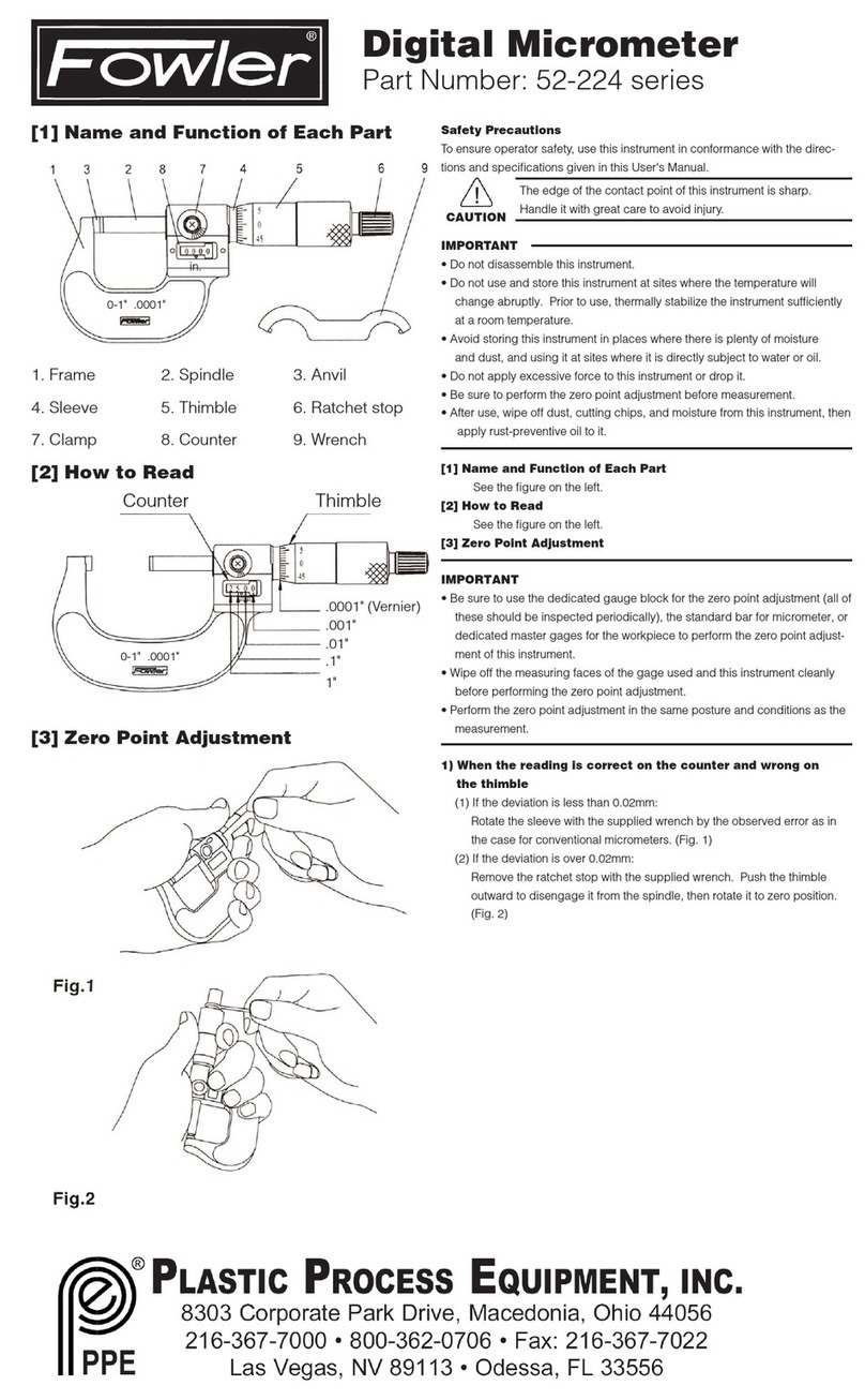
Datcon DT4260 Series User manual

DT4260 xx xx xx xx
AC Current Meter
Operating Instructions

DT4260 xx xx xx xx
Contents
1. About this document.....................................................4
1.1. Function.....................................................................................4
1.2. Target group..............................................................................4
1.3. Symboli m u ed........................................................................4
2. For our safet ..............................................................5
2.1. Authorized per onnel.................................................................5
2.2. Appropriate u e.........................................................................5
2.3. Warning about mi u e...............................................................5
2.4. General afety in truction ........................................................5
2.5. CE conformity............................................................................5
2.6. Environmental in truction ........................................................5
3. Product description.......................................................6
3.1. Delivery configuration................................................................6
3.2. Type de ignation.......................................................................6
3.3. Principle of operation.................................................................7
3.4. Adju tment.................................................................................8
3.5. Di play, indicator ......................................................................9
3.6. Storage and tran port................................................................9
4. Mounting......................................................................10
4.1. General in truction .................................................................10
4.2. Main dimen ion of the in trument..........................................10
4.3. Mounting..................................................................................11
5. Connecting...................................................................13
5.1. Preparing the connection.........................................................13
5.2. Connecting the main ..............................................................14
5.3. Connecting the input................................................................15
5.4. Connecting the limit relay output (option)..............................16
5.5. Connecting the analogue output (option)................................17
5.6. Connecting the RS232 Modbu communication output
(option)............................................................................................18
5.7. Connecting the RS485 Modbu communication output
(option)............................................................................................19
220111006-V020111006-V0

DT4260 xx xx xx xx
6. Displa and manual controls......................................21
6.1. The fir t tart-up.......................................................................21
6.2. Character and mnemonic appearing on the di play............22
6.3. Manual control , di play, indicator ........................................25
7. Setting-up.....................................................................28
7.1. Typing the code (pa word) in................................................28
7.2. The menu tructure.................................................................30
7.3. Di play brightne (01. menu item).........................................31
7.4. Current tran former ratio (IX) (03. menu item)........................32
7.5. Leading zero( ) enable / di able (06. menu item)...................33
7.6. The number of averaged mea urement (08. menu item).....34
7.7. Di play refre h time (09. menu item)......................................36
7.8. Setting limit output (10., 11. menu item)................................37
7.9. Limit output tate di play mode (12. menu item)....................43
7.10. Clear minimum and maximum value (13. menu item)........45
7.11. Analoge output ignal etting (14. menu item)......................46
7.12. A ignment analog output low value to di play value ( caling)
(15. menu item)...............................................................................47
7.13. A ignment analog output high value to di play value
( caling) (16. menu item)................................................................49
7.14. MODBUS communication etting (17. menu item).............51
7.15. Te t (18. menu item)............................................................54
7.16. Changing the u er code (19. menu item)..............................57
7.17. Changing the upervi or code (20. menu item)....................59
7.18. Re etting the default etting (21. menu item).....................61
8. Fault rectification.........................................................62
8.1. Fault finding.............................................................................62
8.2. Repairing..................................................................................62
9. Dismounting................................................................63
9.1. Di mounting procedure...........................................................63
9.2. Di po al...................................................................................63
10. Appendix....................................................................64
10.1. Technical pecification .........................................................64
10.2. Application example..............................................................68
10.3. Setting up the in trument (example).....................................72
10.4. MODBUS etting ..................................................................73
20111006-V0 3

DT4260 xx xx xx xx
1. About this document
1.1. Function
Thi operating in truction manual ha all the information
you need for quick et-up and afe operation of
DT4260 xx xx xx xx.
Plea e read thi manual before you tart etup.
1.2. Target group
Thi operating in truction manual i directed to trained
per onnel. The content of thi manual hould be made
available to the e per onnel and put into practice by them.
1.3. S mbolism used
Information, tip, note
Thi ymbol indicate helpful additional information.
Caution, warning, danger
Thi ymbol inform you of a dangerou ituation that could
occur. Ignoring thi cautionary note can impair the per on
and/or the in trument.
•
List
The dot et in front indicate a li t with no implied
equence.
1
Sequence
Number et in front indicate ucce ive tep in a
procedure.
/
Parting
Parting et in between the element of a li t.
It’ meaning: only one element can be choo en from the li t.
420111006-V020111006-V0

DT4260 xx xx xx xx
2. For our safet
2.1. Authorized personnel
All operation de cribed in thi operating in truction
manual mu t be carried out only by trained and authorized
peciali t per onnel. For afety and warranty rea on , any
internal work on the in trument mu t be carried out only by
DATCON per onnel.
2.2. Appropriate use
A DT4260 xx xx xx xx AC Current Meter mea ure AC
current in 0-1 A or 0-5 A range .
Detailed information on the application range of the
in trument i available in chapter „Product de cription”.
2.3. Warning about misuse
Inappropriate or incorrect u e of the in trument can give
ri e to application- pecific hazard , or damage to y tem
component through incorrect mounting or adju tment.
2.4. General safet instructions
The DT4260 xx xx xx xx i a high-tech in trument requiring
the trict ob ervance of tandard regulation and
guideline . The u er mu t take note of the afety
in truction in thi operating in truction manual, the
country- pecific in tallation tandard a well a all prevailing
afety regulation and accident prevention rule .
2.5. CE conformit
A DT4260 xx xx xx xx i in conformity with the provi ion of
the following tandard :
EN 61326-1:2006 (EMC)
EN 61010-1:2001 (Safety)
2.6. Environmental instructions
Protection of the environment i one of our mo t important
dutie .
Plea e take note of the in truction written in the following
chapter :
• Chapter 3.4. Storage and transport
• Chapter 9.2. Disposal
20111006-V0 5

DT4260 xx xx xx xx
3. Product description
3.1. Deliver configuration
Delivered items The cope of delivery encompa e :
• DT4260 xx xx xx xx
• 1 pc panel ealing (1)
• 2 pc mounting clamp (enclo ed in a nylon bag)
• 1 pc 4 element plug in terminal (analogue or
communication option) (2)
• documentation:
thi operating in truction manual
certification
warranty
3.2. T pe designation
620111006-V020111006-V0

DT4260 xx xx xx xx
3.3. Principle of operation
Area of application The DT4260 xx xx xx xx AC Current Meter enable
0-1 AAC / 0-5 AAC current range to be di played on the
control panel. Large 14.2 mm height LED di play make
proce value ea ily vi ible at a di tance. The di played
value i proportional to the True RMS value of the input
current.
The input current to be mea ured hould be connected to
the in trument’ input hunt through a current tran former.
Ea y on- ite configuration through the front panel
membrane keypad i a major advantage of the
microcontroller-ba ed technology. The configuration
parameter : input range, current tran former ratio, ignal
filtering, output caling, di play refre h rate, limit mode ,
limit value , etc. are tored in EEPROM. The etting are
protected by a two-level pa word again t unauthorized
manipulation.
Option :
• Two normally open relay contact (SPST) for limit
witching or for imple control ta k .
• 4-20 mA / 0-20 mA galvanic i olated calable analogue
output. The output can be active (A) or pa ive (P).
• RS232 galvanic i olated communication output with
MODBUS RTU lave protocol. Only one in trument can be
connected to the PLC or to the computer.
• RS485 galvanic i olated communication output with
MODBUS RTU lave protocol. 32 in trument can be
connected to the PLC or to the computer.
Note: either analogue or communication option can be
implemented at the ame time.
20111006-V0 7

DT4260 xx xx xx xx
Operating principle The mea uring current flow through the input hunt
re i tor. The voltage drop on the hunt re i tor i lead to the
ignal conditioner and TRMS / DC converter tage. The DC
voltage output of thi tage i converted by a 21 bit A/D
converter into digital value. The digital value i proce ed
by a microcontroller. The microcontroller drive the 5 digit
LED di play, proce e the front panel membrane keypad,
drive the limit relay , the analogue output and the
communication output.
Power suppl The in trument ha two power upply ver ion:
DT4260 xx xx xx: 18-40 V AC/DC 3VA / 3.5 W
DT4260 xx xx xx PS: 180-250 V AC/DC 3VA / 3.5 W
3.4. Adjustment
The DT4260 xx xx xx xxcan be adju ted through the 3
button front panel keypad. All configuration parameter are
tored in the in trument EEPROM for unlimited period of
time, even when the upply voltage beeng witched off.
The in trument doe n’t need any internal adju tment.
820111006-V020111006-V0

DT4260 xx xx xx xx
3.5. Displa , indicators
The following figure how the front panel of the in trument:
1. 5 digit LED di play di playing the mea ured value and
the mnemonic me age .
2. „Rel1” yellow indicator for indicating that limit output 1 i
in “on- tate” (LIMIT1).
3. „Rel2” yellow indicator for indicating that limit output 2 i
in “on- tate” (LIMIT2).
4. „Status” yellow indicator for indicating that a ucce full
data exchange ha granted through the communication
output.
3.6. Storage and transport
Thi in trument hould be tored and tran port in place
who e climatic condition are in accordance with Chapter
10.1. Technical specifications, a de cribed under the
title: Environmental condition .
The packaging of DT4260 xx xx xx xx con i t of enviroment-
friendly, recyclable cardboard i u ed to protect the
in trument again t the impact of normal tre e occurring
during tran portation. The corrugated cardboard box i
made from environment-friendly, recyclable paper. The
inner protective material i nylon, which hould be di po ed
of via peciali ed recycling companie .
20111006-V0 9

DT4260 xx xx xx xx
4. Mounting
4.1. General instructions
U e the enclo ed eal between the in trument and the
panel when mounting the in trument to a ure IP 65 from
the front.
Mounting positions Select a mounting po ition you can ea ily read the di play
reach for mounting and connecting the in trument and that
minimi e the hazard of water, du t or dump getting into the
in trument.
4.2. Main dimensions of the instrument
10 20111006-V020111006-V0

DT4260 xx xx xx xx
4.3. Mounting
Preparator steps
Dimensions of panel
cutout
The in trument i hou ed in a DIN tandard 96 x 48 mm
ABS ca e. It can be fix in the panel with the two enclo ed
mounting clamp .
1. Cut-out the panel according to the figure how above.
The cut-out need pecial tool , it mu t be carried out by
trained peciali t per onnel.
20111006-V0 11

DT4260 xx xx xx xx
Mounting with the
mounting clamps
2. Put on the enclo ed eal onto the in trument ca e from
the rear ide and fit it to the in trument holding frame
(Figure tep 2).
3. Put the in trument into the prepared cut-out until it
po ible and check the fitting of the eal between ca e and
mounting urface.
4. Put one of the enclo ed mounting clamp onto the tip of a
crewdriver (A) and put the clamp with the help of the
crewdriwer into the hole on the ide of the in trument.
5. Pu h the mounting clamp with your finger tip a far a
you can while keeping the ca e in it’ po ition.
Plea e do not exerci e force higher than nece ary, a it
may cau e damage to the clamp.
Repeat the 4., 5. tep with the other clamp.
12 20111006-V020111006-V0

DT4260 xx xx xx xx
5. Connecting
5.1. Preparing the connection
Alway ob erve the following afety in truction :
• Connect or di connect only in the complete ab ence of
line voltage
• You hould take note the data concerning on the
overcurrent protection in in tallation.
• U e only a crewdriver with appropriate head
Select connection
cable
Preparing cables
Take note the uitability of the connecting cable
(wire cro - ection, in ulation, etc.).
You may u e either olid conductor or flexible conductor.
In ca e of u ing flexible conductor u e crimped wire end.
In ca e of main connection the wire cro - ection hould
be 1.0 mm2 (min.).
In ca e of 5 AAC input current the wire cro - ection hould
be 1.5 mm2 (min.).
In ca e of connection communication cable take note the
concerning pre cription (www.modbu .org).
It’ an important rule that the power cable and ignal
cable hould lead on a eparate way.
Prepare the cable for the connection.
Strip approx. 8 mm in ulation.
In ca e of u ing flexible cable, crimp the cable end.
20111006-V0 13

DT4260 xx xx xx xx
5.2. Connecting the mains
Wiring plan, connecting
the instrument to the
mains
( ee al o “Application
example”)
In ca e of DC upply the
polarity i indifferent
The following figure how the wiring plan, connecting the
DT4260 xx xx xx PS type in trument to the main :
Wiring plan, connecting
the instrument to the
mains
( ee al o “Application
example”)
In ca e of DC upply the
polarity i indifferent
The following figure how the wiring plan, connecting the
DT4260 xx xx xx type in trument to the power upply:
1. Loo en terminal crew .
2. In ert the wire end into the open terminal according to
the wiring plan.
3. Screw the terminal in.
4. Check the hold of the wire in terminal by pulling on
them firmly.
14 20111006-V020111006-V0

DT4260 xx xx xx xx
5.3. Connecting the input
Wiring plan, connecting
the input
( ee al o “Application
example”)
The following figure how the wiring plan, connecting the
input to the current tran former:
1. Loo en terminal crew .
2. In ert the wire end into the open terminal according to
the wiring plan.
3. Screw the terminal in.
4. Check the hold of the wire in terminal by pulling on
them firmly.
20111006-V0 15

DT4260 xx xx xx xx
5.4. Connecting the limit rela outputs (option).
Wiring plan, connecting
the limit rela outputs
( ee al o “Application
example”)
The following figure how the wiring plan, connecting the
limit relay output :
1. Loo en terminal crew .
2. In ert the wire end into the open terminal according to
the wiring plan.
3. Screw the terminal in.
4. Check the hold of the wire in terminal by pulling on
them firmly.
16 20111006-V020111006-V0

DT4260 xx xx xx xx
5.5. Connecting the analogue output (option).
Wiring plan, connecting
the analogue output
( ee al o “Application
example”)
Be careful the polarity of
the cable .
The following figure how the wiring plan, connecting
analogue output in ca e of active (DT4260 xx xx IA xx) or in
ca e of pa ive (DT4260 xx xx IP xx) output:
1. Loo en terminal crew .
2. In ert the wire end into the open terminal according to
the wiring plan.
3. Screw the terminal in.
4. Check the hold of the wire in terminal by pulling on
them firmly.
20111006-V0 17

DT4260 xx xx xx xx
5.6. Connecting the RS232 Modbus communication
output (option).
Wiring plan, connecting
the RS232 output
( ee al o “Application
example”)
Be careful the polarity of
the cable .
The following figure how the wiring plan, connecting the
RS232 Modbu communication output
(DT4260 xx xx RS2 xx):
The RS-232 Modbu communication output hould be u ed
for hort di tance communication. The maximum di tance i
< 10-15 m, it depend on the communication peed.
You can find u eful information about the Modbu
communication at www.modbu .org.
1. Loo en terminal crew .
2. In ert the wire end into the open terminal according to
the wiring plan.
3. Screw the terminal in.
4. Check the hold of the wire in terminal by pulling on
them firmly.
18 20111006-V020111006-V0

DT4260 xx xx xx xx
5.7. Connecting the RS485 Modbus communication
output (option).
Wiring plan, connecting
the RS485 output
( ee al o “Application
example”)
Be careful the polarity of
the cable .
The following figure how the wiring plan, connecting the
RS485 Modbu communication output
(DT4260 xx xx RS4 xx):
The RS-485 Modbu communication output hould be u ed
for long di tance communication. 32 in trument can be
connected to the PLC or to the computer.
You can find u eful information about the Modbu
communication at www.modbu .org.
1. Loo en terminal crew .
2. In ert the wire end into the open terminal according to
the wiring plan.
3. Screw the terminal in.
4. Check the hold of the wire in terminal by pulling on
them firmly.
20111006-V0 19

DT4260 xx xx xx xx
Checking the
connections
Check if the cable are connected properly (have you
connected all the cable , have you connected to the right
place, do not the cable-end touch each other).
Put the instrument
under suppl voltage
Put the instrument under suppl voltage
After you have completed the connection , put the
in trument under upply voltage. If the upply connection i
correct the di play give light.
The factory default value of the current tran former ratio i 1
i.e. the in trument di play the value of the input current
(the econdary current of the current tran former).
Setting the current tran former ratio you can find in
Chapter 7.
20 20111006-V020111006-V0
Table of contents
Other Datcon Measuring Instrument manuals
Datcon
Datcon DT9000 N User manual
Datcon
Datcon DT1102 V User manual
Datcon
Datcon DT9502 User manual
Datcon
Datcon DT9000 User manual
Datcon
Datcon DT4220 E Series User manual
Datcon
Datcon DT4240 Series User manual
Datcon
Datcon DT4200 User manual
Datcon
Datcon DT9002 User manual

Datcon
Datcon DT7000 User manual

Datcon
Datcon DT920 User manual

