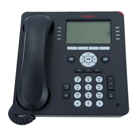
Avaya 6424D+M User manual

555-104-630
Issue 2
June 1991
DEFINITY Communications
SystemGeneric 2
and System 85
Wiring

Copyright ©1991 AT&T
All Rights Reserved
Printed in U.S.A.
Notice
While
reasonable efforts were made to ensure that the
information in this document was complete and accurate
at the time of printing, AT&T can assume no responsibility
for any errors. Changes and corrections to the
information contained in this document may be
incorporated into future reissues.
Federal Communications Commission (FCC)
Statement
This equipment generates, uses, and can radiate radio-
frequency energy and, if not installed and used in
accordance with the instruction manual, may cause
interference to radio communications. It has been tested
and found to comply with the limits for a Class A
computing device pursuant to Subpart J of Part 15 of FCC
Rules, which are designed to provide reasonable
protection against such interference when operated in
a
.
commercial environment.
Operation of this equipment in a residential area is Iikely
to cause interference, in which case the user at his/her
own expense will be required to take whatever measures
may be required to correct the interference.
Security
In rare instances, unauthorized individuals make
connections to the telecommunications network through
the use of remote access features. in such event,
applicable tariffs require that the customer pay all network
charges for traffic. AT&T cannot be responsible for such
charges, and will not make any allowance or give any
credit for charges that result from unauthorized access.
Trademarks
DEFINITY is a registered trademark of AT&T. In this
document, DEFINITY Communications System Generic 2
is often abbreviated to DEFINITY Generic 2 or Generic 2
Ordering Information
The ordering number for this document is 555-104-530.
To order this document, call the AT&T Customer
Information Center at 1-800-432-6600 (in Canada,
1-800-255-1242). For more information about AT&T
documents, refer to the
Business Communications
Systems Publications Catalog
(555-000-010).
Comments
To comment on this document, return the comment card
at the back of the document.
Prepared by
AT&T Technical Publications Department, Denver,
Colorado.

CONTENTS
ABOUT THIS DOCUMENT
INTENDED AUDIENCES
PREREQUISITE SKILLS AND KNOWLEDGE
ORGANIZATION OF THIS GUIDE
HOW TO USE THIS DOCUMENT
TRADEMARKS AND SERVICE MARKS
RELATED RESOURCES
HOW TO MAKE COMMENTS ABOUT THIS DOCUMENT
1. OVERVIEW: SYSTEM 85 AND DEFINITY GENERIC 2 WITH TRADITIONAL
MODULES
MAJOR COMPONENTS FOR SYSTEM 85 AND DEFINITY GENERIC 2 WITH TRADITIONAL MODULES
SYSTEM ADJUCTS
CROSS-CONNECT FIELDS
TERMINALS AND TERMINAL ADJUNCTS
CONNECTIVITY
GENERIC 2 WITH TRADITIONAL MODULE
2. MDF/IDF DESIGN: SYSTEM 85 AND DEFINITY GENERIC 2
WITH TRADITIONAL MODULES
RECOMMENDED TERMINAL BLOCKS
RECOMMENDED FRAMES FOR TERMINAL- BLOCKS
DESIGNING THE MDF
DESIGNING THE MDF FOR A RAISED FLOOR
RECOMMENDATION FOR IDF DESIGNS
xi
xi
xi
xii
xiii
xiii
xiii
xv
1-1
1-1
1-3
1-4
1-4
1-4
1-7
2-1
2-1
2-5
2-9
2-24
2-31
INSERT LABELS
2-32
iii

iv
CONTENTS
3. ELECTRICAL PROTECTION: SYSTEM 85 AND DEFINITY GENERIC 2
WITH TRADITIONAL MODULES
TYPES OF ELECIRICAL HAZARDS
PROTECTING AGAINST HAZARD EXPOSURE
PROTECTING THE SWITCH
PROTECTING OTHER EQUIPMENT
PRIMARY PROTECTION
ENHANCED PRIMARY PROTECTION
SECONDARY PROTECTION
RECOMMENDED PROTECTORS
PROTECTION MATRIX
4. PORT PACKS/DCP REPEATERS: SYSTEM 85 AND DEFINITY GENERIC 2
WITH TRADITIONAL MODULES
PORT CIRCUIT PACKS
DCP REPEATERS
5. INSTALLATION EXAMPLE: SYSTEM 85 AND DEFINITY GENERIC 2 WITH
TRADITIONAL MODULES
SIZING THE MDF
CONSTRUCTING THE MDF
6. OVERVIEW: DEFINITY GENERIC 2 WITH UNIVERSAL MODULES
MAJOR COMPONENTS-MULTICARRIER MODULE
SYSTEM ADJUNCTS
CROSS-CONNECT FIELDS
TERMINALS AND TERMINAL ADJUNCTS
CONNECTIVITY
MAJOR COMPONENTS-SINGLE CARRIER MODULE
3-1
3-1
3-1
3-2
3-2
3-4
3-5
3-5
3-5
3-7
4-1
4-1
4-5
5-1
5-1
5-3
6-1
6-1
6-3
6-4
6-4
6-4
6-4

CONTENTS
v
7. MDF/IDF DESIGN: DEFINITY GENERIC 2 WITH UNIVERSAL MODULES
7-1
RECOMMENDED TERMINAL BLOCKS
7-1
RECOMMENDED FRAMES FOR TERMINAL BLOCKS
7-5
DESIGNING THE MDF
7-9
DESIGNING THE MDF FOR A RAISED FLOOR
7-24
RECOMMENDATIONS FOR IDF DESIGNS
7-31
INSERT LABELS
7-32
8. ELECTRICAL PROTECTION: DEFINITY GENERIC 2
WITH UNIVERSAL MODULES
RECOMMENDED PROTECTORS
PROTECTION MATRIX
9. PORT PACKS: DEFINITY GENERIC 2 WITH UNIVERSAL MODULES
PORT CIRCUIT PACKS
DCP REPEATERS
10. INSTALLATION EXAMPLE: DEFINITY GENERIC 2
WITH UNIVERSAL MODULES
SIZING THE MDF
CONSTRCUTING THE MDF
11. BRI: DEFINITY GENERIC 2 WITH UNIVERSAL MODULES
BRI TERMINALS
BRI POWER SUPPLIES
12. ADJUNCT POWER SUPPLIES
INDIVIDUAL POWER SUPPLIES
BULK POWER SUPPLY
8-1
8-1
8-2
9-1
9-1
9-4
10-1
10-1
10-3
11-1
11-1
11-2
12-1
12-1
12-2

vi
CONTENTS
13. FIBER OPTICS
13-1
LCTT
13-1
CONNECTORS
13-1
PADDLEBOARD RANGE LIMITATIONS
13-1
14. INSERT LABELS
GLOSSARY
14-1
GL-1
INDEX
IN-1

CONTENTS
vii
LIST OF FIGURES
Figure 1-1. System 85 and DEFINITY Generic 2 with Traditional Module
Connectivity
Figure 2-1. Maximum Column 1500 Pairs (Five 300-Pair Terminal Blocks)
Figure 2-2. Jumper Placement
Figure 2-3. Six Type-1 Frames with 18,000-Pair Capacity
Figure 2-4. Seven Type-2 Frames with 16,800-Pair Capacity
Figure 2-5. Overall Equipment Wiring Plan
Figure 2-6. Four-Area MDF
Figure 2-7. Combined Trunk and Line Ports
Figure 2-8. Separated Trunk and Line Ports
Figure 2-9. Zone Arrangement of Type-1 Frame — Plan View
Figure 2-10. Zone Arrangement of Type-1 Frame — Front View, Zone 2
Figure 2-11. Zone Arrangement of Type-2 Frame — Plan View
Figure 2-12. Zone Arrangement of Type-2 Frame — Front View, Zone 2
Figure 2-13. Closet Cross-Connects Using Type-1 Frames
Figure 2-14. Floor Template - 18 Inch Tile (L472366)
Figure 2-15. Floor Template - 24 Inch Tile (L472367)
Figure 2-16. Floor Template - Cabinet Lineup (L472368)
Figure 2-17. Floor-Secured Frame Installation
Figure 2-18. Example of Label Filled In
Figure 3-1. Placement of Electrical Protectors on CO Side of Switch
Figure 5-1. 7-Module System Wall-Mounted on Type-1 Frame
Figure 5-2. 7-Module System Mounted on Self-Supporting Type-1 Frame, Front
Figure 5-3. 7-Module System Mounted on Self-Supporting Type-1 Frame, Rear
Figure 5-4. 7-Module System Mounted on Self-Supporting Type-2 Frame, Front
Figure 5-5. 7-Module System Mounted on Self-Supporting Type-2 Frame, Rear
Figure 7-1. Maximum Column 1500 Pairs (Five 300-Pair Terminal Blocks)
Figure 7-2. Jumper Placement
Figure 7-3. Six Type-1 Frames with 18,000-Pair Capacity
Figure 7-4. Seven Type-2 Frames with 16,800-Pair Capacity
1-6
2-3
2-4
2-6
2-7
2-10
2-15
2-16
2-17
2-19
2-19
2-21
2-21
2-23
2-26
2-27
2-28
2-30
2-33
3-3
5-4
5-4
5-5
5-6
5-6
7-3
7-4
7-6
7-7

viii
CONTENTS
Figure 7-5.
Figure 7-6.
Figure 7-7.
Figure 7-8.
Figure 7-9.
Figure 7-10.
Figure 7-11.
Figure 7-12.
Figure 7-13.
Figure 7-14.
Figure 7-15.
Figure 7-16.
Figure 7-17.
Figure 7-18.
Figure 7-19.
Figure 10-1.
Figure 10-2.
Figure 10-3.
Figure 10-4.
Figure 10-5.
Figure 10-6.
Figure 11-1.
Figure 14-1.
Figure 14-2.
Figure 14-3.
Figure 14-4.
Figure 14-5.
Figure 14-6.
Figure 14-7.
Figure 14-8.
Figure 14-9.
Figure 14-10.
Figure 14-11.
Overall Equipment Wiring Plan: DEFINITY Generic 2 with Universal
Modules
CPC Wall Field Configuration
Four-Area MDF
Combined Trunk and Line Ports
Separated Trunk and Line Ports
Zone Arrangement of Type-1 Frame — Plan View
Zone Arrangement of Type-1 Frame — Front View, Zone 2
Zone Arrangement of Type-2 Frame — Plan View
Zone Arrangement of Type-2 Frame — Front View, Zone 2
Closet Cross-Connects Using Type-1 Frames
Floor Template - 18 Inch Tile (L472366)
Floor Template - 24 Inch Tile (L472367)
Floor Template - Cabinet Lineup (L472368)
Floor-Secured Frame Installation
Example of Label Filled In
7-Module System Wall-Mounted on Type-1 Frames
7-Module System Wall-Mounted on Type-2 Frames
7-Module System Mounted on Self-Supporting Type-1 Frame, Front
7-Module System Mounted on Self-Supporting Type-1 Frame, Rear
7-Module System Mounted on Self-Supporting Type-2 Frame, From
7-Module System Mounted on SeIf-Supporting Type-2 Frame, Rear
Special ISDN Wiring for Satellite Closet
Insert Labels - Partial Reproductions
7-10
7-13
7-16
7-17
7-18
7-20
7-20
7-21
7-22
7-23
7-26
7-27
7-28
7-30
7-33
10-4
10-5
10-5
10-6
10-7
10-7
11-2
14-5
14-6
14-7
14-8
14-9
14-10
14-11
14-12
14-13
14-14
14-15

CONTENTS ix
Figure 14-12. Insert Labels - Partial Reproductions
14-16
Figure 14-13. Insert Labels - Partial Reproductions
14-17
Figure 14-14. Insert Labels - Partial Reproductions
14-18

x
CONTENTS
TABLE 2-1.
TABLE 2-2.
TABLE 2-3.
TABLE 2-4.
TABLE 2-5.
TABLE 2-6.
TABLE 3-1.
TABLE 3-2.
TABLE 3-3.
TABLE 4-1.
TABLE 4-2.
TABLE 4-3.
TABLE 7-1.
TABLE 7-2.
TABLE 7-3.
TABLE 7-4.
TABLE 7-5.
TABLE 7-6.
TABLE 7-7.
TABLE 8-1.
TABLE 8-2.
TABLE 9-1.
TABLE 9-2.
TABLE 9-3.
TABLE 11-1.
TABLE 12-1.
TABLE 13-1.
TABLE 14-1.
LIST OF TABLES
300-Pair Terminal Blocks
100-Pair Terminal Blocks
Type-1 Frame Ordering Information
Mounting Methods
Module Allocation per Zone with Type-1 Frame
Module Allocation per Zone with Type-2 Frame
Loop Ranges for Protected Hybrid Terminals
Loop Ranges for Protected Digital Terminals
System 85 and DEFINITY Generic 2 with Traditional Modules Protection
Matrix
Port Circuit Pack Cabling
Terminals and Peripherals Served by Port Circuit Packs
Voice Terminal Loop Ranges
300-Pair Terminal Blocks
100-Pair Terminal Blocks
2-2
2-2
2-8
2-14
2-18
2-20
3-8
3-8
3-9
4-2
Type-1 Frame Ordering Information
Type-2 Frame Ordering Information
Mounting Methods
Module Allocation per Zone with Type-1 Frame
Module Allocation per Zone with Type-2 Frame
Generic 2 with Universal Modules Protection Matrix
Loop Ranges for Protected Terminals
Port Circuit Pack Cabling
Terminals and Peripherals Served by Port Packs
Voice Terminal Loop Ranges
Power Supply Distance Limits
Maximum Loop Lengths for the 346A Power Unit
System 85 and DEFINITY Generic 2 Fiber-Optic Paddleboard Ranges
Numerical List of Insert Labels
4-3
4-4
7-2
7-2
7-8
7-9
7-15
7-19
7-21
8-3
8-3
9-2
9-3
9-4
11-3
12-2
13-2
14-2

ABOUT THIS DOCUMENT
This document follows as closely as possible the guidelines of the AT&T premises distribution system
(PDS) as presented in the
Premises Distribtion
Systems
Phase 1.
While the PDS covers all distribution
media (copper and fiber), this document is concerned primarily with the simplified design of the main
distribution frame (MDF) for AT&T System 85 and DEFINITY® Communications System Generic 2
(hereafter abbreviated as DEFINITY Generic 2 or Generic 2). The MDF as discussed in this document
is the major cross-connect field for an installation and is located in or near the equipment room.
This document is intended as a supplement to the AT&T
Premises Distribution System Design Guide
(555-400-602) and does not duplicate information in the PDS guide. This document supplies detail only
where the PDS guide does not — that is, on the specifics of designing an MDF and intermediate
distribution frames (IDFs) for System 85 and DEFINITY Generic 2. Therefore, the following topics that
are
●
●
●
●
covered in the
Premises Distribution System Design Guide
are not covered in this document:
Information outlets (IO) at the workstations
Horizontal subsystem (installation cable)
Riser subsystem (distribution cable)
Campus subsystem (distribution cable)
INTENDED AUDIENCES
This document is intended primarily for the premises services consultant (PSC) who is charged with
designing an MDF and IDF for a System 85 or DEFINITY Generic 2 installation. It also may prove
helpful to those who are charged with designing wiring installations for other systems that link to a
System 85 or DEFINITY Generic 2, or for sales, marketing, and engineering personnel who want to
familiarize themselves with these guidelines.
REASON FOR REISSUE
This document has been reissued to incorporate addenda 1 and 2 into Issue 1. The addenda pages that
have been incorporated into this issue contain new or changed information that is indicated by margin
rule marks
|
in text. These are changes to the issue 1 document. These changes include new information
about adjunct power and terminal loop lengths, protection devices, synchronization clock, single carrier
cabinet module, TN754B and TN746B to port pack listings, and floor templates.
xi

xii
ABOUT THIS DOCUMENT
PREREQUISITE SKILLS AND KNOWLEDGE
This document assumes that you are familiar with the PDS installation guidelines and hardware. If you
are not, read the
Premises Distribution System Design Guide (555-400-602)
before you read this
document.

ABOUT THIS DOCUMENT xiii
ORGANIZATION OF THIS GUIDE
This document consists of the following chapters and appendixes:
●
●
●
●
●
●
●
●
●
●
●
●
●
●
Chapter 1,
Overview: System 8.5 and DEFINITY Generic
2
with Traditional Modules
— A brief
description of the System 85 and DEFINITY Generic 2 traditional modules’ principal components,
including remote module interfaces (RMIs) and remote group interfaces (RGIs), and their operation
Chapter 2,
MDF/IDF Design: System 85 and DEFINlTY Generic 2 with Traditional Modules
—
Detailed guidelines for designing an MDF and general guidelines for designing an IDF
Chapter 3,
Electrical Protection: System
85
and DEFINITY Generic 2 with Traditional Modules
—
A discussion of primary, enhanced primary, secondary, and combination electrical protectors for the
System 85 and DEFINITY
Generic 2 with traditional modules including remote modules when
distribution cabling is exposed to electrical hazards.
Chapter 4, Port Packs/DCP Repeaters: System 85 and DEFINITY Generic 2 with Traditional
Modules —
Cross-references between port circuit packs, their terminations on the MDF, and the
terminals that they serve, as well as a discussion of Digital Communications Protocol (DCP)
repeaters for digital terminals
Chapter 5,
Installation Example: System 85 and DEFINITY Generic 2 with Traditional Modules —
An example of an MDF designed to accommodate a hypothetical seven-module system 85 or
DEFINITY Generic 2 with traditional modules
Chapter 6, Overview: DEFINITY Generic 2 with Universal Modules — A guide to the major
differences and important features of DEFINITY Generic 2 with universal modules that are not
available in System 85 and DEFINITY Generic 2 with traditional modules
Chapter 7,
MDF/IDF Design: DEFINITY Generic 2 with Universal Modules
— Designing the MDF
and IDF for DEFINITY Generic 2 with universal modules
Chapter 8, Electrical Protection: DEFlNITY Generic 2 with Universal Modules — Electrical
protection scheme for DEFINITY Generic 2 with universal modules
Chapter 9,
Port Packs: DEFINTY Generic
2
with Universal Modules
— Port packs and terminals
supported in the Generic 2 universal configurations
Chapter 10, Installation Example: DEFINITY Generic 2 with Universal Modules — A sample
installation of a DEFINITY Generic 2 with universal modules
Chapter 11,
BRI: DEFINITY Generic 2 with Universal Modules — A
brief overview of basic rate
interface wiring principles, terminals, and power supplies as they apply to DEFINITY Generic 2 with
universal modules
Chapter 12,
Adjunct Power Supplies —
Information and guidelines for adjunct power supplies, loop
ranges, and applications for System 85 and DEFINITY
Generic 2
Chapter 13,
Fiber-Optics —
A brief chapter explaining fiber-optics as it applies to the System 85
and DEFINITY Generic 2
Chapter 14,
Insert Labels
—
Partial reproductions of the sheets of insert labels used to identify cable
terminations on the MDF and IDFs
A glossary and index appear at the end of this document.

xiv ABOUT THIS DOCUMENT
HOW TO USE THIS DOCUMENT
Chapters 1 through
5
apply to System 85 and DEFINITY Generic 2 with traditional modules. Chapters
6 through 11 apply to DEFINITY
Generic 2 with universal modules. Chapters 12 through 14 apply to
adjunct power supplies, fiber-optics, and insert labels; this information is common to both System 85
and DEFINITY Generic 2.
TRADEMARKS AND SERVICE MARKS
●
●
●
●
●
●
●
●
●
IBM® is a registered trademark of International Business Machines Corp.
IBM Token Ring LAN® is a registered trademark of International Business Machines Corp.
MS-DOS® is a registered trademark of Microsoft Corp.
CP/M® is a registered trademark of Digital Research Inc.
UNIX® is a registered trademark of AT&T.
DIMENSION® is a registered trademark of AT&T.
DEFINITY® is a registered trademark of AT&T. In this document, DEFINITY Communications
System Generic 2 is often abbreviated to DEFINITY Generic 2, Generic 2, DEFINITY
G2, or G2.
Linx® is a registered trademark of Illinois Tool Works Linx (TTW).
Delta® is a registered trademark of Porta Systems Corp.
RELATED RESOURCES
Following are a list and brief descriptions of additional documents that you may find helpful.
●
Premises Distribution System Design Guide
(555-400-602). A document for readers who are
familiar with distribution systems and the hardware and cabling necessary for their construction
Provides step-by-step instruction in designing a PDS for a building or a campus of buildings even
when the specific voice or data systems are not known, plus information on specific PDS
components and methods. Not intended as a tutorial in PDS.
NOTE: The Premises
Distibution System Design Guide
(555-400-602) cannot be ordered from the
AT&T Customer Information Center. Provided on a proprietary basis to select, certified PDS
vendors and to PSCs who attend the PDS design training course.
●
DEFINTY™ Communic
ation System Generic 2 and System 85 Equipment Room Floor Plans and *
Specifications
(555-104-603). An instruction document for preparing an equipment room floor plan
for DEFINITY Generic 2 and System 85. Includes general req
uirements, customer responsibilities,
preparation of the layout, and guidelines for protecting equipment on construction sites.
●
DEFINITY™ Communications System Generic 2 and System 85 Electrical Protection, Grounding,
and Exposure Checklist (555-104-120). A checklist of conditions that must be met to ensure
adequate electrical protection for a DEFINITY Generic 2 or System 85 installation. For engineering,
plant maintenance, installation, and quality acceptance personnel. Included are electrical protection,
grounding, and exposure reference information and checklists.

ABOUT THIS DOCUMENT
xv
●
Telecommunication Electrical Protection
(350-060). Information and training material for engineers
responsible for the electrical protection of personnel and users of telecommunication networks,
systems, and equipment from lightning and power surges, power-line contacts, induction, and ground
potential rise.
●
AT&T System 75 Wiring
(555-200-111). A document for planning, designing, and installing a
System 75 wiring installation using Z-100, 110, or 66 cross-connect systems.
● DEFINITY™ Communications System and System 75 and System 85 Terminals and Adjuncts
Reference
(555-015-201). Concise physical and functional descriptions of the voice terminals,
voice-terminal adjuncts, data modules, and data terminals that can be used with a System 75 or
System 85.
●
ISDN
Terminal Installation and Tests
(555-021-101). Point-to-point installation information between
terminals and the satellite closet. This volume includes information about BRI installation.
●
An Introduction to DEFINITY™ 75/85 Communications System Generic 2
(555-104-020). A general
description for prospective customers,
account teams, and others who need an overview of
DEFINITY Communications System Generic 2. Included are the following major functions that are
part of or associated with the system: principal voice and message features and peripherals for users;
in-depth descriptions of system components and their capabilities network features and
configurations; available methods for managing the system; and AT&T’s support for planning and
installation, for training, and for maintenance.
●
An Introduction to DEFINITY™ Communi
cations System, Generic 2 (555-104-020). A general
description for prospective customers, account teams, and others who need an overview of
DEFINITY Generic 2. Includes information based on desktop, system, network, system
management and support points of view.
Information on features, peripherals, and system capacity
is also covered.
●
DEFINITY™ Communications System Generic and System 85 System Description
(555-104-201). A
document intended primarily for sales and technical personnel to provide general technical
information on DEFINITY Generic 2 and System 85.
● DEFINITY™ Communications System Generic 2 and system 85 Installation (555-104-104).
document for service technicians to instruct them in the installation and connection of switching
equipment.
● 800 Series DSX —
General Description, DSX Systems (365-301-102).
Transition procedures
explaining:
—
The installation of new 800-series digital signals cross-onnect (DSX) equipment in new lineups
parallel to lineups of older DSX equipment
—
The installation of new 800-series DSX equipment in new bays adjacent to older DSX equipment
in the same lineup
—
The installation of the new 800-series DSX equipment to replace older DSX equipment
●
DEFINITY™ Communications System and System 75 and System 85 Terminal Installation and Tests
(555-015-104). A procedural document for those who administer, install and test modules, voice
terminals, and cross-connect equipment.

xvi
ABOUT THIS D0CUMENT
HOW TO MAKE COMMENTS ABOUT THIS DOCUMENT
Reader comment cards are in the back of this document. While we have tried to make this document fit
your needs, we are interested in your suggestions for improving it and urge you to fill one out.
If the reader comment cards have been removed from this document please send your comments to:
AT&T
Technical Publications Department
Room 22-2C11
11900 North Pecos Street
Denver, Colorado 80234

1. OVERVIEW: SYSTEM 85 AND DEFINITY GENERIC 2
WITH TRADITIONAL MODULES
AT&T System 85 and DEFINITY® Generic 2 Communications System (hereafter abbreviated to
DEFINITY Generic
2 or Generic 2) with traditional modules are communications systems with
multimodule architecture that provide integrated voice and data switching via a state-of-the-art
communications processor (called the
common control
or
CC),
a time-multiplexed switch (TMS), and
the communications modules. A single System 85 or DEFINlTY Generic 2 with traditional module
capability can contain up to 31 modules with each module providing as many as 1536 analog ports. The
multimodule architecure uses the TMS as the link between the modules.
A single System 85 or DEFINIIY Generic 2 with traditional modules can support from 300 to 32,000
lines. When a System 85 or DEFINITY Generic 2 with taditional modules is linked in a distributed
communications system (DCS)
—
a network of switches such as other System 85s, DEFINITY Generic
2 with traditional modules, AT&T DIMENSION® PBXs with FP8-3, and AT&T System 75s — the
DCS is capable of supporting up to 100,000 lines.
This chapter presents an overview of the components of System 85 and DEFINITY Generic 2 with
traditional modules that are major factors in the design of a wiring installation. For more comprehensive
information on System 85, see the System 85
System Description Reference Manual
(555-103-201). For
more details on DEFINITY Generic 2s with traditional modules, see the
DEFINITY™ Communications
System Generic 2 and System 85 System Description Reference Manual (555-104-201). See the
DEFINITY Generic 2 with Traditional Module
section at the end of this chapter for a brief list of
features supported only by DEFINITY Generic 2 with traditional modules.
MAJOR COMPONENTS FOR SYSTEM 85 AND DEFINITY GENERIC 2 WITH TRADITIONAL
MODULES
A System 85 or DEFINITY Generic 2 with traditional module consists of four major operating units: the
common control (CC), the module control (MC), the ports, and the TMS.
A System 85 or DEFINITY Generic 2 with traditional module requires from 2 cabinets for a single-
module system to as many as 128 cabinets for a multimodule system with the maximum number of
lines. When a System 85 or DEFINITY Generic 2 with traditional modules is housed in 2 cabinets, it
does not require the TMS function; the MC and port units are combined in 1 cabinet.
CC
The CC is the communications processor, or master controller; it contains a group of components that
control, supervise, and coordinate system operations.
1-1

1-2
OVERVIEW: SYSTEM 85 AND DEFINlTY GENERIC 2 WITH TRADITIONAL MODULES
MC
The MC, or communications switching module,
is the basic building block of the multimodular
architecture. Each MC is capable of supporting up to 1536 analog ports and 256 simultaneous full-
duplex conversations.
Remote Modules
System 85 and DEFINITY Generic 2 with traditional modules can have remote modules located up to
25,000 ft away from the CC and TMS.
The number of remote modules cannot exceed the number of
modules at the central switch location (15 maximum). The call control (including call processing,
administration, and maintenance) is multiplexed onto the fiber-optic link; thus all system features are
available to remote locations. Remote modules with optically-remoted peripheral interfaces (ORPI) for
attendant consoles have a maximum range of 13,000 ft.
The recommended fiber size for remote-module links is the AT&T graded index multimode fiber with a
62.5-micron core and 125-micron outer diameter.
RGI
Small groups of voice and data terminal users at remote locations can be connected to the central switch
by a digital service level-1 (DS1) link that uses remote-group interface (RGI) circuit packs as the DS1
interfaces. The RGI circuit packs are installed in the DSl/MFAT carrier of the central module and in
the remote-group housing (RGH) at the remote location.
The maximum distance that a remote group can be located from the central module is 100 mi over T1
lines with repeaters. A direct cable connection between the central module and the remote group can be
a maximum of 1310 ft with the option switches on the RGI circuit packs properly set. To extend the
distance beyond 1310 ft. a channel service unit (CSU) must be installed at each end of the DS1 link.
Remote Module and Remote Group Documents
Detailed information about the configurations, designs, hardware components, and construction of fiber-
optic links for remote modules and DS1 links for remote groups appears in
About This Document.
Port Packs
Port packs are circuit packs that are housed in the carriers in the port and MC cabinets. These circuit
packs provide the line and trunk circuits for System 85 and DEFINTTY Generic 2 with traditional
modules. The circuit packs also contain the interface that allows the MC to govern the connections.

OVERVIEW: SYSTEM 85 AND DEFINITY GENERIC 2 WITH TRADITIONAL MODULES
1-3
TMS
The TMS is a time-multiplexed, space-division switch that connects modules for communications in a
time-slot information between the modules and the TMS. The TMS processor, on command from the
501CC processor, directs the interconnections between the modules and the TMS.
SYSTEM ADJUNCTS
The installation of most System 85 and DEFINITY
Generic 2 traditional modules is accompanied by
one or more system adjuncts that provide the customer with administrative or application functions that
do not reside on the switch. One adjunct is the AT&T Audio Information Exchange (AUDIX). The
other two adjuncts are the applications processors (APs) — the AP16 and the 3B5 AP.
AUDIX
AUDIX is a voice-mail system that can operate with System 85, DEFINITY
Generic 2, or PBXs made
by other manufacturers. AUDIX enables subscribers to create, store, send, and receive spoken messages
and to distribute voice memos using just the telephone. The AUDIX processor uses disk storage for the
encoded voice messages.
When AUDIX is operating with a System 85 or DEFINITY
Generic 2 with traditional modules, it
connects to the data communications interface unit (DCIU) of the switch through synchronous control
channels for data transmission and to analog ports for voice transmission. Several PBXs can share one
AUDIX adjunct.
More detailed descriptions of AUDIX appear in the
AUDIX Reference Manual
(585-300-201).
APs
The AP16 and 3B5 AP are installed with the System 85s and DEFINITY
Generic 2 traditional modules
to provide customers with office automation functions and administrative functions for the system. The
APs also can provide the office automation functions as standalone units. Both APs are housed in
switch-size cabinets.
Auxiliary Cabinet
An auxiliary cabinet is not actually a system adjunct but a cabinet used to house shelf- and rack-
mounted peripheral equipment for the system.
Auxiliary cabinets usually are located in the equipment
room with the adjunct cabinets, but they can be located at other sites to serve equipment such as an AP,
that is remotely located.

1-4
OVERVIEW: SYSTEM 85 AND DEFINITY GENERIC 2 WITH TRADITIONAL MODULES
CROSS-CONNECT FIELDS
Cross-connect fields are a major component in the installation of a System 85 or DEFINITY Generic 2
with a traditional module. They are the termination points for equipment cabling and distribution
cabling. Cross-connect fields are also where the connections are made between those termination points
in order to establish communications paths throughout the system. Two major cross-connect fields are
used with System 85 and DEFINITY Generic 2 with traditional modules — the main distribution frame
(MDF) and the intermediate distribution frame (IDF).
The MDF (called the
administration field
in previous documentation) is the largest cross-connect field in
a System 85 or DEFINITY
Generic
2
with traditional module installation; the MDF can be either frame-
or wall-mounted. It is located in, or sometimes near, the equipment room. The MDF is the field on
which terminations and cross-connections for central office (CO) trunks, equipment cabling, and
distribution cabling are made.
IDF is a term applied to any cross-connect field other than an MDF. The IDF is usually located in a
satellite closet or at the building entrance facility (BEF). On the IDF the terminations and cross-
connections are made for the distribution cabling from the MDF, from other IDFs, and from the
installation cabling from the information outlets (IOs). IDFs are smaller than MDFs and are installed in
quantities that are dictated by the overall wiring design.
TERMINALS AND TERMINAL ADJUNCTS
A variety of terminals and terminal adjuncts connect to the System 85 and DEFINITY Generic 2 with
traditional modules. When you are designing the wiring installation according to the basic or enhanced
premises distribution system (PDS) guidelines, the types of terminals and peripherals being installed at
the workstations should have no effect on the overall wiring design. The basic guideline calls for two
wiring pairs in the distribution cable, from the MDF to the IDF, and one 4-pair cable in the horizontal
wiring, from the IDF to the information outlet (IO) for each workstation. The enhanced guideline calls
for three wiring pairs in the distribution cable and two 4-pair cables in the horizontal wiring for each
workstation.
When you are designing the wiring installation according to bid-specific requirements, the types and
quantities of terminals and peripherals may affect the sizing of the distribution cables. See
About This
Document,
for information on where to find detailed information on wiring for specfic terminals and
peripherals.
CONNECTIVITY
Figure 1-1,
System
85 and DEFINITY Generic 2 with Traditional Module Connectivity
illustrates the
connections for a basic voice path. The path flows from the point where the trunk enters the facility
through the major components of the system’s building wiring to its termination on a voice terminal at a
workstation.
The path starts on a one-pair circuit that runs from the CO to the equipment room. In the equipment
room, the wire terminates at the network interface. A connection using jumper wire or patchcord is
Other manuals for 6424D+M
4
This manual suits for next models
19
Table of contents
Other Avaya Telephone manuals

Avaya
Avaya one-X 9600 Series Instructions for use

Avaya
Avaya 6424D+M User manual

Avaya
Avaya J179 User manual

Avaya
Avaya IP Office 9608 User manual

Avaya
Avaya 3616 Series User manual

Avaya
Avaya IP Office 2030 User manual

Avaya
Avaya ETR Operating instructions

Avaya
Avaya 3701 User manual

Avaya
Avaya T3 (IP) Compact User manual

Avaya
Avaya IP OFFICE 2420 User manual