EQKC COMBI COOLER
FläktGroup DC_8931GB 20180202_R0 We reserve the right to make changes without prior notice
Installation and maintenance instructions
9
COOLING UNIT
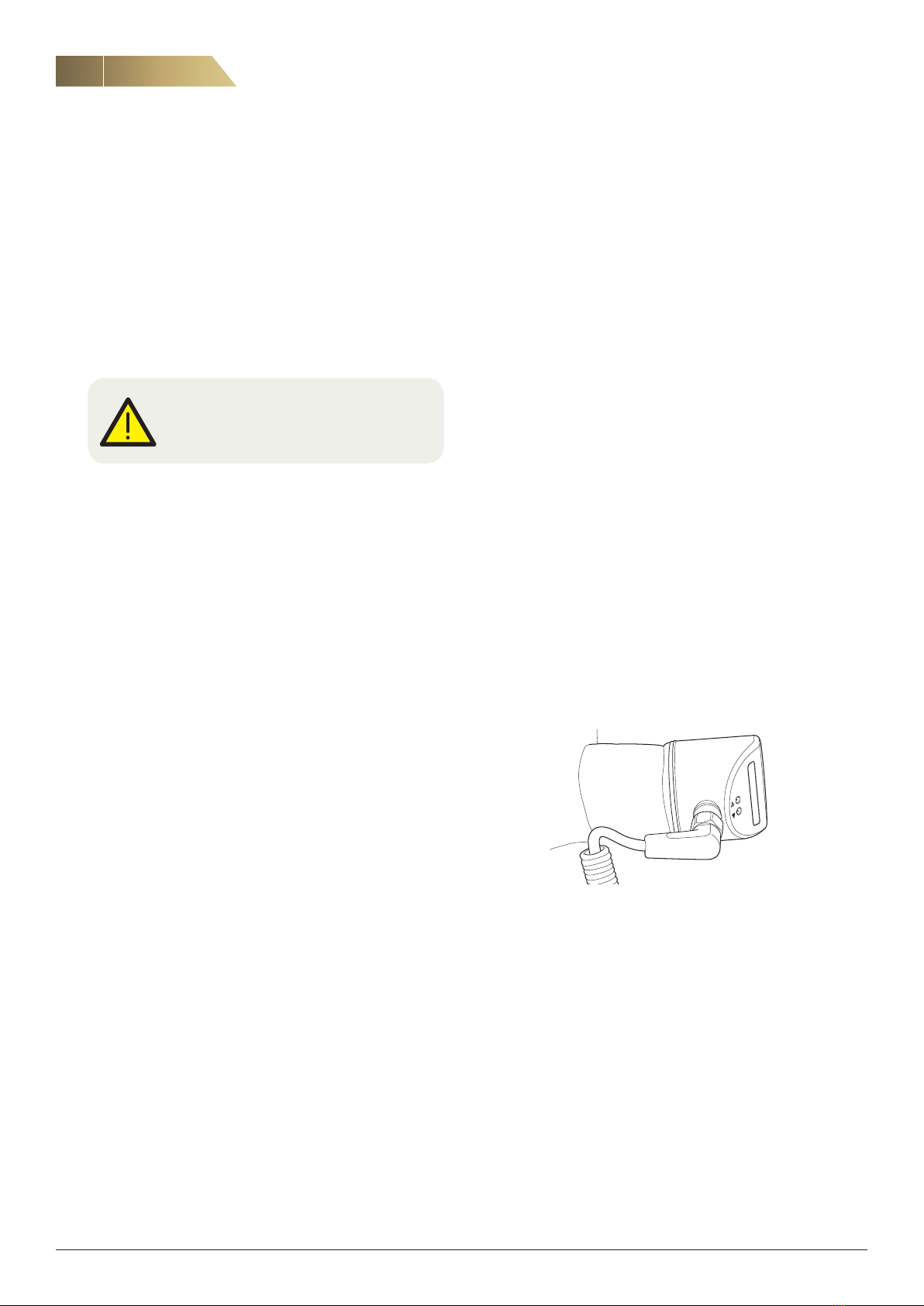
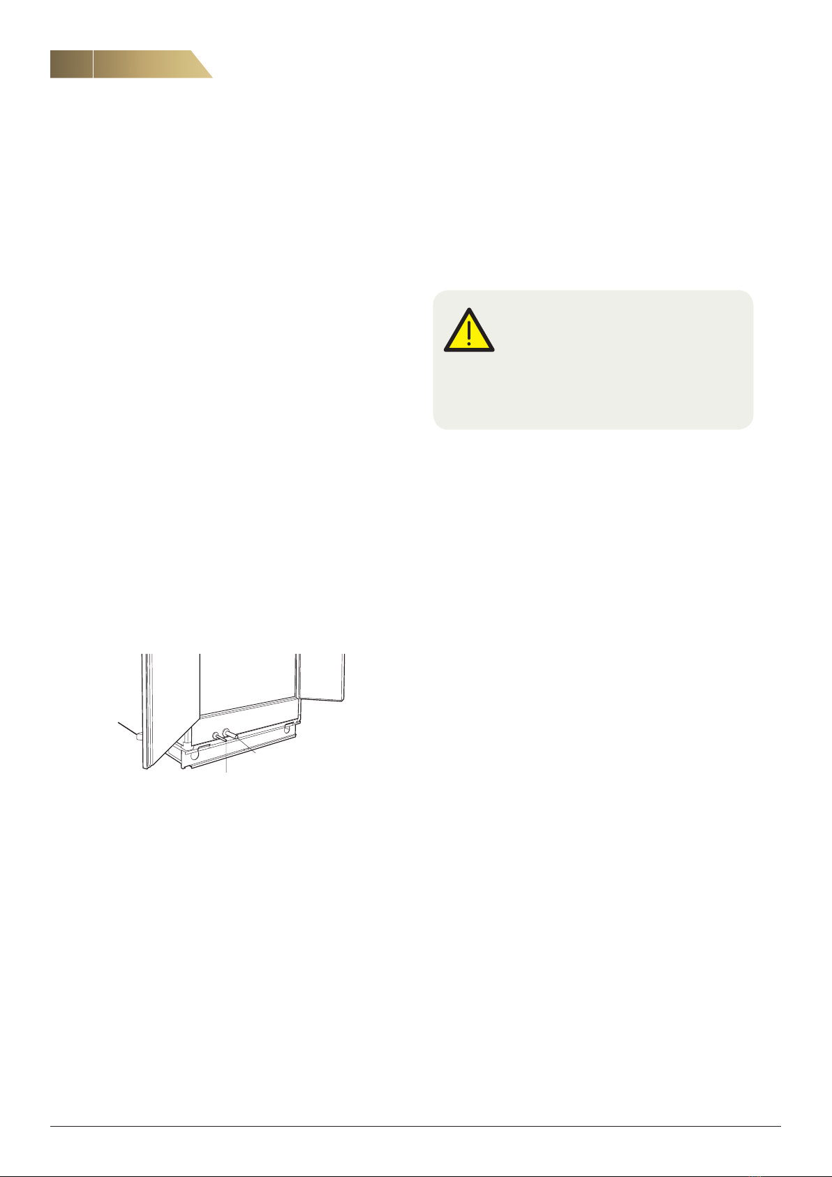
Inspecting the sight glasses
The unit has two sight glasses, one mounted between the con-
denser coil and subcooling coil, and the other downstream
of the subcooling coil.
The purpose of the first sight glass is to check whether gas is
entering the subcooler. If this is the case, the subcooler will
not operate optimally and will just act as an extension of the
condenser coil. It is difficult to avoid a small amount of gas, but
large amounts can be an indication that there is too little refri-
gerant in the system.
Because the amount is adjusted at the factory, this means that
there is a risk of leakage in the refrigerant circuit.
Checking subcooling
Subcooling can be checked by measuring the temperature
difference between the inlet and outlet of the subcooling coil.
Superheating
The correct degree of superheating is important for optimum
and reliable operation. If superheating is too great, the hot
vapour downstream of the compressor will get unnecessarily
hot. If superheating is insufficient there is a risk of liquid leaking
into the compressor. This can result in compressor damage.
Condensation temperature
At times the condensation temperature can be quite high,
almost 60 °C. This is normal. The system is designed for such
temperatures.
Inspection
The function of the cooling unit can be tested by checking
the temperature difference with the control unit.
This check can also be carried out during maintenance in
order to check the cleanliness/performance of the heat
exchangers in the system.
AFTER STARTUP, CHECK THE FOLLOWING:
• Operating flows
• Flow to the supply air coil and main circuit correct
• Information to personnel undertaken
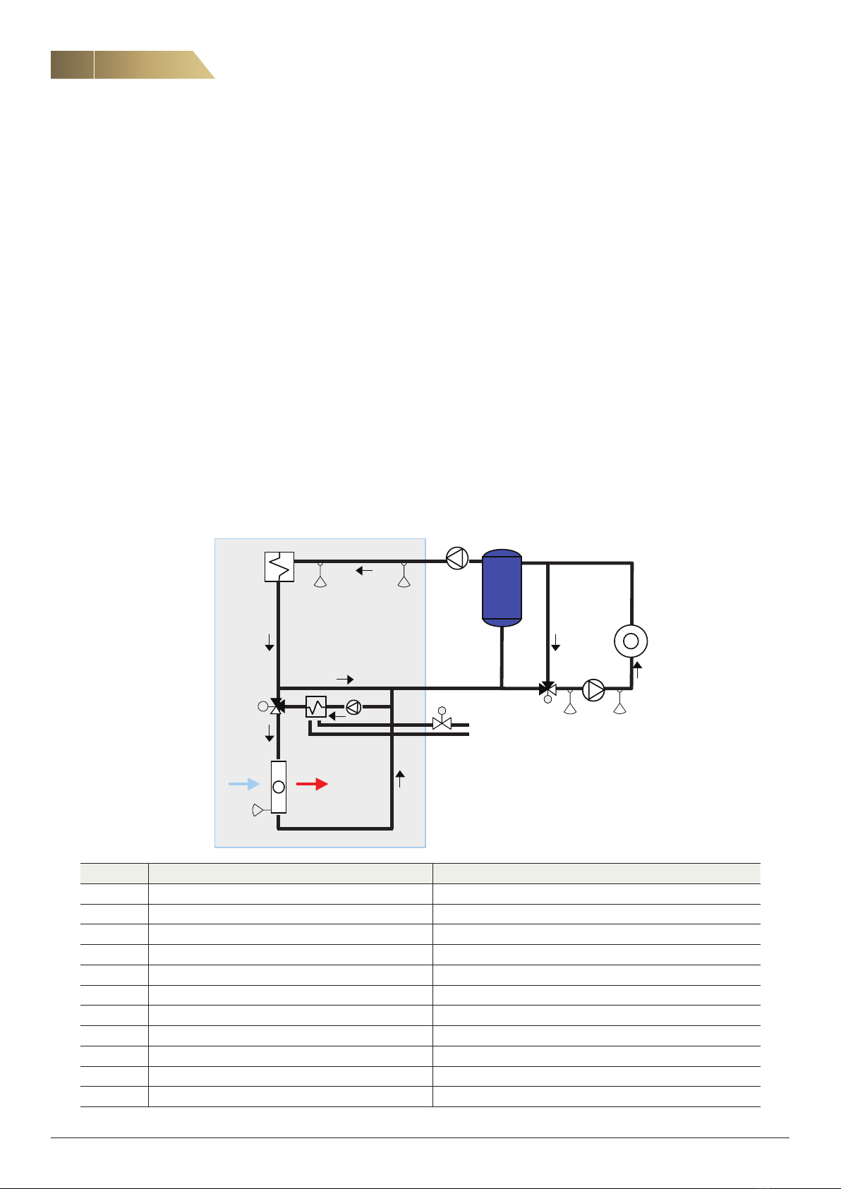
FUNCTION
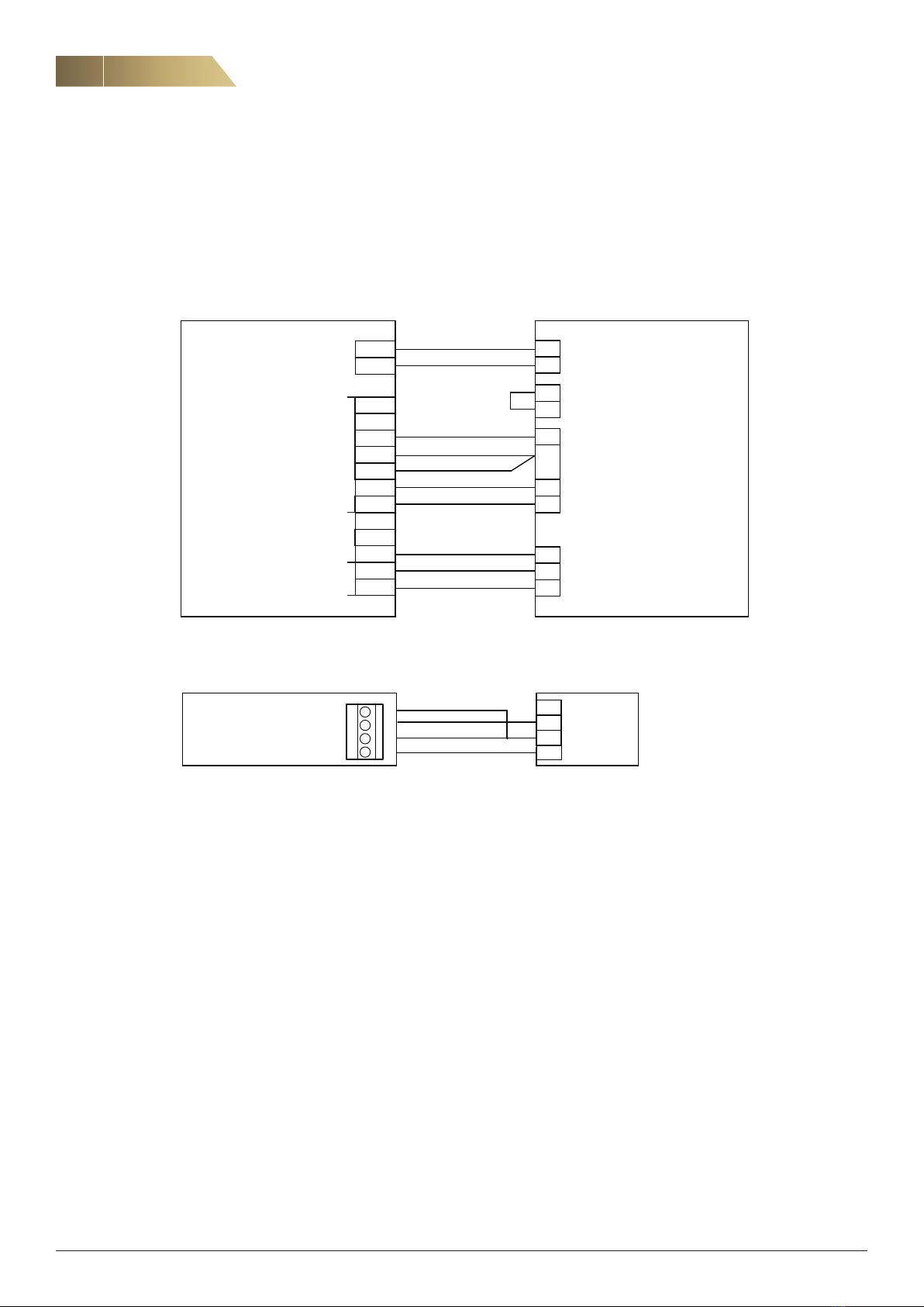
The compressors are connected in three cooling stages.
The outgoing water temperature depends on whether there is
a risk of condensation in the chilled beams or not. See Page 9
for a description of the control unit.
The air handling unit can be used for both supply air and extract
air control. The cooling unit must be interlocked by the extract
air fan and main pump (and any outdoor thermostat). It is im-
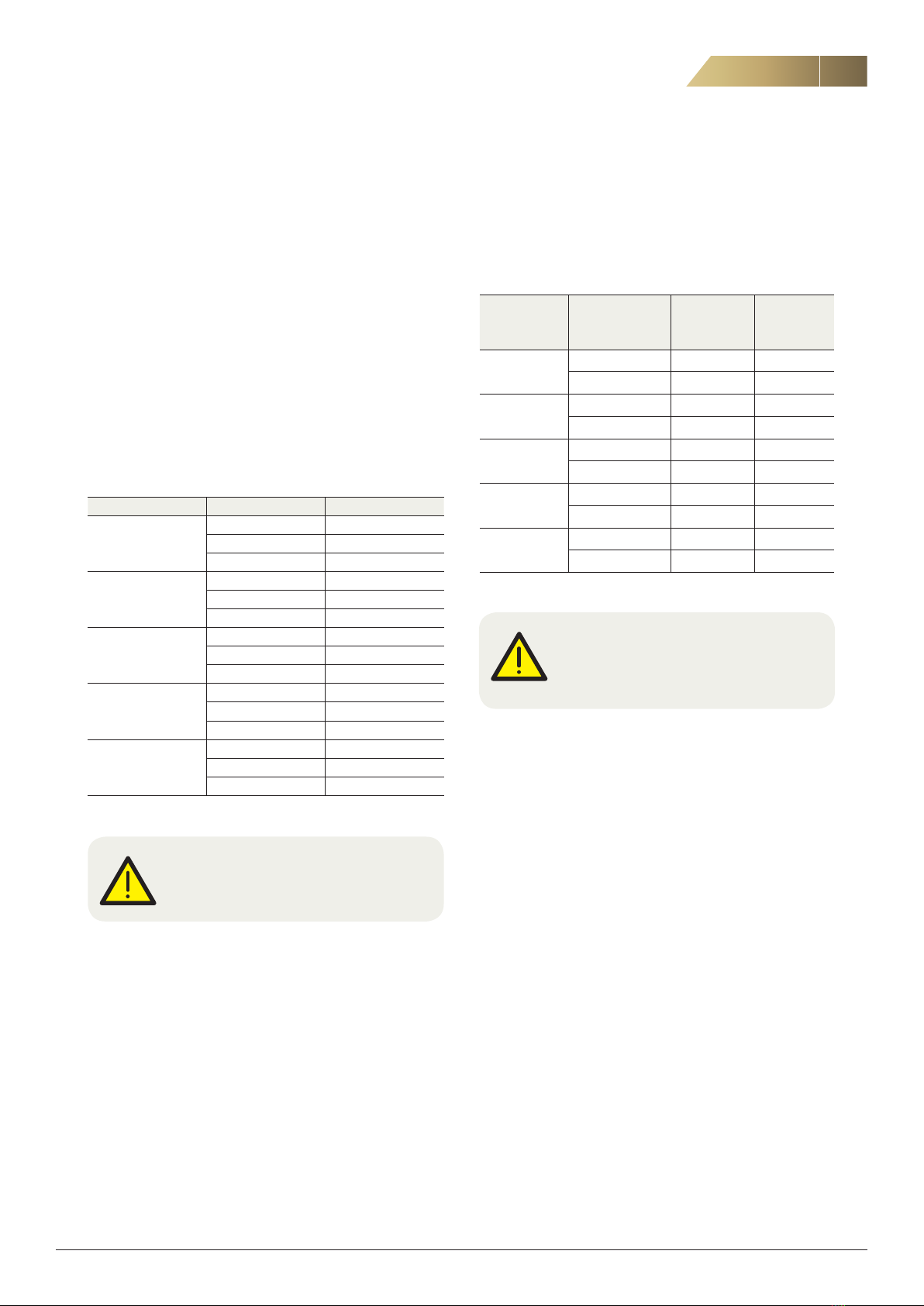
eQ size Power model
Nominal power
with water at
18/12
014
1 21
2 29
3 34
018
1 26
2 34
3 43
023
1 36
2 46
1 55
032
1 55
2 69
3 80
041
1 69
2 86
3 101
portant that the compressors stop if the extract air fan stops.
The cooling unit is also internally interlocked by a flow switch
in the water circuit and the pump for the supply air coil.
Because of the location of the condenser coil, the cooling re-
covery function cannot operate in the unit while the cooling unit
is in operation.
Overriding the chilled beam circuit valve
If the heating load on the chilled beam circuit exceeds the
design cooling power, the valve for the outgoing water tem-
perature to the chilled beam circuit will be overridden, so as
to prioritize the supply air coil. This is to ensure that the supply
air coil can dehumidify air when required. If this function is
not used in the integrated control unit, it must be added to
the controller that replaces it.
Capacity regulation
The capacity of each circuit is regulated individually. If the
pressure is too high, one or both of the compressors will be
shut down. This is to maintain as high a cooling power as
possible and to prevent a shutdown that would require a
manual reset. The compressors are restarted in sequence.
Water-cooled condenser
A water-cooled condenser can be ordered as an option.
If the condenser heat cannot be released to the extract air,
the condenser temperature will rise. In that case the water-
cooled condenser is automatically engaged at 60 °C to
reduce the temperature.
COOLING UNIT