FläktGroup MultiMAXX HN11 User manual

MultiMAXX ® HN
OPERATION MANUAL

MultiMAXX HN
2FläktGroup DC-2011-0143-GB 2022-07/R6 • Subject to modifications
Product overview

MultiMAXX HN
FläktGroup DC-2011-0143-GB 2022-07/R6 • Subject to modifications 3
Type code
H N 2 2 . U W A R A P . B K D I 2 0 0 1 G A Z H 2 . 2 0 0 2
Size
1 = Size 1
2 = Size 2
3 = Size 3
4 = Size 4
5 = Size 5
Capacity stage *
1 = Capacity stage 1
2 = Capacity stage 2
3 = Capacity stage 3
4 = Capacity stage 4
Unit type
U = Recirculating air unit
M = Air mixing unit
Unit function
S = Only heating/steam
W =
Only heating/heating water (PWW, PHW)
V = Heating/cooling with condensate
drain
P = Heating/cooling with condensate
pump
Heat exchanger
A = Cu/Al max. 130 °C; 1.6 MPa,
louvre spacing 2.5 mm
C = Cu/Cu max. 130 °C; 1.6 MPa,
louvre spacing 3 mm
R = Fe/Fe Zn, circular pipes,
louvre spacing 4 mm **
S = Fe/Fe Zn, elliptical pipes,
louvre spacing 3 mm **
T = Fe/Fe Zn, elliptical pipes,
louvre spacing 6 mm **
Medium connection (seen against the air flow)
O = From top
R = From right
L = From left
Heat exchanger outlet connections
A = Male thread
O = Without thread
Air outlet louvre
A = Nozzle - heating only
B = Basic louvre
C = Secondary ceiling louvre - manual control
D = Secondary ceiling louvre with actuator, 230 V, open/
close
L = Directional louvre - heating only
K = Flange
P = Secondary louvre Basic
T = Gate curtain - heating only
U = Secondary wall louvre - manual control
V = Four-side anemostat (ceiling-mounted)
W = Secondary wall louvre with actuator, 230 V, open/clo-
se
Z = Two-side anemostat - heating only
O = Without louvre ***
Air side accessories
20 = Mixed air module, direct
21 = Mixed air module, lateral
23 = Shut-off damper
25 = Flexible connection adapter
26 = Rectangular duct 150
27 = Rectangular duct 1000
28 = Symmetrical elbow 90°
29 = Asymmetrical elbow 90°
31 = Canopy
32 = Rain canopy
33 = Accessory protection grille
34 = Passage duct for slanted roofs
35 = Roof outlet hood
36 = Bag filter - module
37 = Flat filter - module
38 = Spare bag filter for "35"
39 = Spare bag filter for "36"
40 = Spare fleece for flat filters “37”
49 = Roof passage duct with plinth
51 = Wall frame
52 = Flange (for re-circulation units)
Ohne Auslass
Electric motor version
AC-motors
A =
3x400 V 2-stage - low speed, wide-blade fan 5)
B =
3x400 V 2-stage - high speed, wide-blade fan
5)
C =
3x400 V 3-stage - low speed, wide-blade fan
3)
D =
1x230 V low speed, wide-blade fan 4)
E =
1x230 V high speed, wide-blade fan 5)
R =
3x400 V 2-stage - high speed, curved-blade fan 2)
S =
3x400 V 3-stage, curved-blade fan
V =
3x500 V 3-stage, curved-blade fan
U =
without motorized fan
EC-motors
Y =
1x230 V stepless, curved-blade fan
Z =
3x400 V stepless, curved-blade fan 2)
Electrical components
K = Terminal block (in a plastic box)
S = Fan switch
R = MATRIX®
Heat exchanger casing types
A =
Comfort - painted steel in RAL 9002, plastic corner guards RAL 7000
B = Comfort - RAL shade as requested
D = Industry - painted steel RAL 7000
Size
1 = Size 1
2 = Size 2
3 = Size 3
4 = Size 4
5 = Size 5
Material/configuration
0 = Normal environment
8 = Ecodesign (only for 25, 26, 36, 38, 39)6)
Mixing chamber damper actuators
0 = Actuator installation setup
1 = Manual control
2 = Actuator 230 V open / closed
3 =
Actuator 230 V open / closed + potentiometer
4 =
Actuator 230 V open / closed + end switch
5 = Actuator 230 V + return spring
6 =
Actuator 24 V open / closed
7 =
Actuator 24 V (0... 10 V)
Filtration class/Electrical components
0 = Without filter, without differential pressure
switch
2 = G2/ without differential pressure switch
3 = G3/ without differential pressure switch (only
for Flat filter)
4 = G4/ without differential pressure switch
5 = G2/ with differential pressure switch
6 = G3/ with differential pressure switch (only for
Flat filter)
7 = G4/ with differential pressure switch
9 = F7/ with differential pressure switch
Suspension bracket
53 = Kompakt C
54 = Studio
55 = Modular (for wall mounting)
56 = Ceiling suspension bracket
Modular with accessories
0 = Without accessories 8 = 25+36+23+51
1 = 25+20+51 9 = 25+37+23+51
2 = 25+36+20+51 A = 26+36
3 = 25+37+20+51 B = 26+37
4 = 25+21+29+51 C =
5 = 25+36+21+29+51 E = Ecodesign (25(26)+36+20+51)6)
6 = 25(26)+37+21+29+51 W = Without accessories for units with
a vertical outlet
7 = 25+23+51
Ceiling suspension
bracket 56
0 = Without threaded
rod
2 = Threaded rod 2 m
1 = Threaded rod 1 m 3 = Threaded rod 3 m
Controller type
2 = MATRIX 2000
3 = MATRIX 3000
4 = MATRIX 4000
Control package 001-999
Controller
IP54; including room temperature
sensor 903454
G = MATRIX OP21I
I = MATRIX OP31I
K = MATRIX OP44I
L = MATRIX OP50I
M = MATRIX OP51I
Z = without controller
Controller location
Control unit
A = Stand-alone controller
B = Integrated controller
Slave unit
D = Without controller
or
1) Control system MC4 is not included with the basic unit model
2) Not available for sizes 1 and 2
3) Not available for sizes 1 and 5
4) Not available for sizes 3, 4, 5
5) Not available for size 5
6) Only for sizes 2 and 4
* Matches the number of rows in the heat exchanger
** Heating only
*** Only with Industry casing
Electric motor version
AC-motors
1AC =
1-speed, 230 V, 50 Hz
2AC = 2-speed, 400 V, 50 Hz
3AC = 3-speed, 400 V, 50 Hz
EC-motors
1EC =
continuous, 230 V, 50 Hz
3EC = stepless, 400 V, 50 Hz
Auxiliary functions
Circulation
000 = Without auxiliary functions
Z00 =
Outlet louvre control
- actuator 230 V, open/close
00F =
Filter clogging indication
Z0F =
Outlet louvre control
- actuator 230 V, open/close
Filter clogging indication
Air mixing (not for 1AC)
0KF =
Mixing chamber damper control -
actuator 230 V, open/close or return
spring actuator 230 V
Filter clogging indication
ZKF
=
Outlet louvre control
- actuator 230 V, open/close, Mixing
chamber damper control
-
actuator 230 V, open/close or re-
turn spring actuator 230 V
Filter clogging indication
Unit type
U = Recirculation
M = Air mixing
MC 4 M 3AC ZKF
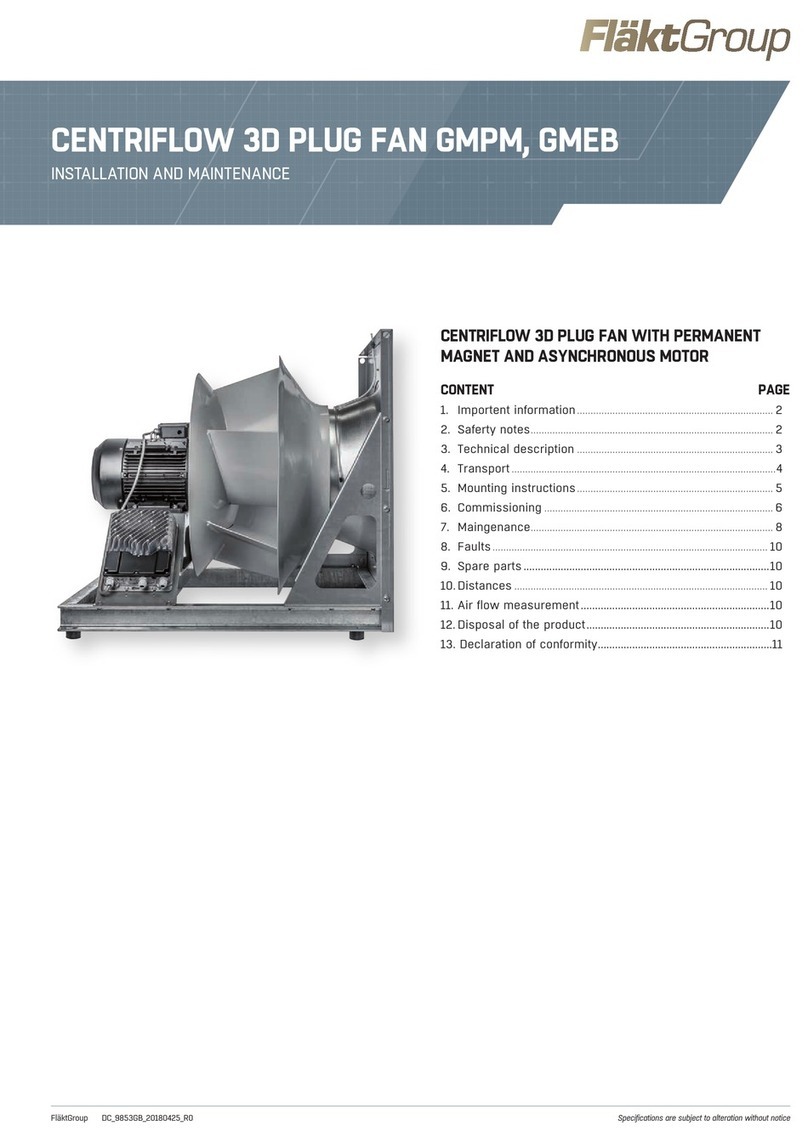
Table of contents MultiMAXX HN
4FläktGroup DC-2011-0143-GB 2022-07/R6 • Subject to modifications
Table of contents
Product overview ........................................................................... 2
Type code ....................................................................................... 3
Table of contents ............................................................... ............ 4
1 Safety and user information ........................................................... 6
1.1 Scope of application ..................................................................................... 6
1.2 Symbols ....................................................................................................... 6
1.3 Health and safety at work ............................................................................ 7
1.4 Use ............................................................................................................... 8
1.5 Safety regulations and standards ................................................................ 9
1.6 Changes and modifications .......................................................................... 9
1.7 Spare parts .................................................................................................. 9
1.8 Staff selection and specialist qualifications .................................................. 9
2 Technical data ................................................................................ 10
2.1 Unit components ........................................................................................ 10
2.2 Material specifications ................................................................................ 11
2.3 Unit versions .............................................................................................. 12
2.4 Unit description ......................................................................................... 14
2.5 Operating conditions .................................................................................. 14
2.6 Unit dimensions ........................................................................................ 15
2.7 Heat exchanger outlet connections............................................................. 17
2.8 Unit weight and water volume in the heat exchanger ................................. 17
2.9 Operational limits ...................................................................................... 17
2.10 Acoustic and electrical data ....................................................................... 18
2.11 Condensate pump ...................................................................................... 19
2.12 Air side accessories .................................................................................... 21
2.13 Ecodesign requirements according to Commission Regulation (EU) 2016/
2281 ............................................................................................................ 22
3 Shipping and storage .................................................................... 23
3.1 Shipping .................................................................................................. 23
3.2 Unit handling and moving........................................................................ 23
3.3 Storage ...................................................................................................... 24
4 Mounting......................................................................................... 25
4.1 Installation site load-bearing capacity ......................................................... 25
4.2 Ceiling mounting ......................................................................................... 25
4.3 Wall mounting ............................................................................................. 26
4.4 Safe distance ............................................................................................. 27
4.5 Unit mounting ............................................................................................ 28
4.6 Unit casing fitting ....................................................................................... 28
5 Media connections......................................................................... 31
5.1 Pipe connection ......................................................................................... 31
5.1 Connection dimensions .............................................................................. 31
5.3 Condensate drain connection ..................................................................... 31
5.4 Condensate pump connection .................................................................... 32
6 Electrical connections.................................................................. 33
6.1 Wiring diagrams ........................................................................................ 33
6.2 Plastic electrical enclosure/Steel electrical enclosure ................................ 34
6.3 3-speed, 3-phase electric motor 3 x 400 V (3 x 500 V), 50 Hz (electric
motor designation C, S, V) wiring diagram ................................................ 36
6.4 2-speed, 3-phase electric motor 3 x 400 V, 50 Hz (electric motor
designation A, B, R) wiring diagram ........................................................... 37
6.5 1-speed, 1-phase electric motor 1 x 230 V, 50 Hz (electric motor
designation D, E) wiring diagram ............................................................... 38

MultiMAXX HN Table of contents
FläktGroup DC-2011-0143-GB 2022-07/R6 • Subject to modifications 5
6.6 1-speed stepless EC-motor 1 x 230 V, 50 Hz (electric motor
designation Y) wiring diagram .....................................................................39
6.7 3-speed stepless EC-motor 3 x 400 V, 50 Hz (electric motor
designation Y) wiring diagram .....................................................................39
6.8 Overview of MATRIX printed circuit boards .................................................40
6.9 Controller/room temperature sensor location .............................................46
6.10 Electrical connections with MATRIX ............................................. 48
6.11 MATRIX.Net network and shielding connection...........................................58
6.12 Connecting the MC4 control unit, potentiometer or control system on site..65
6.13 Mixing chamber damper and shut-off damper actuator wiring diagram ......69
6.14 Differential pressure switch wiring diagram .................................................69
6.15 Louvre actuator wiring diagram....................................................................69
6.16 Condensate pump wiring diagram ...............................................................69
7 Commissioning ............................................................................ 70
7.1 Commissioning prerequisites ......................................................................70
7.2 Bleeding air from the system .......................................................................71
7.3 Condensate drain and condensate pump inspection...................................71
7.4 Operational inspection of frost protection (only for mixing units) ................72
7.5 Operation ....................................................................................................72
7.6 Operating instructions .................................................................................73
7.7 Shutting off the unit .....................................................................................73
7.8 Termination resistors ..................................................................................74
7.9 Settings addresses .....................................................................................76
7.10 Starting the unit. ..........................................................................................78
7.11 Data connectivity check ...............................................................................79
7.12 Checking control inputs and outputs ...........................................................80
7.13 Functions when used with MATRIX ............................................................82
8 Maintenance and troubleshooting .............................................. 89
8.1 Maintenance ...............................................................................................89
8.2 Quarterly maintenance ...............................................................................91
8.3 Six-monthly maintenance ...........................................................................93
8.4 Annual maintenance ...................................................................................93
8.5 Before a period of cooling ...........................................................................94
8.6 Troubleshooting ...........................................................................................95
9 Dismantling and disposal ............................................................ 98
9.1 Dismantling .................................................................................................98
9.2 Disposal ......................................................................................................98
Declaration of conformity ........................................................... 99
Copyright note
Distributing and copying of this document, its sale and the disclosure of its content is strictly prohibited without express
prior consent. Any violation of this clause will result in liability for damages. All rights in relation to patent, utility model
or industrial design registration are reserved.

Safety and user information MultiMAXX HN
6FläktGroup DC-2011-0143-GB 2022-07/R6 • Subject to modifications
1 Safety and user information
This is the original operation manual verified by the manufacturer.
MultiMAXX HN heating, ventilation and cooling units are designed and manufactured
in accordance with state-of-the-art engineering and technological trends, and in com-
pliance with established EU safety and technical standards and codes.
MultiMAXX heating units are safe in operation and meet strict quality standards.
Their technical quality level meets the high user requirements for easy maintenance
and servicing.
Nevertheless, each unit may pose a risk to the user or third parties, may break down
or cause other damage. Safety regulations must therefore be observed at all times.
The operation and maintenance of the unit must therefore be conducted in keeping
with regulations and user standards; failure to follow them could result in death, serious
injury, environmental damage and/or other damage
Observing the safety instructions in this operation manual will help avoid damage to
the unit and other damage, and ensure safe and reliable operation of MultiMAXX HN
units.
The safety aspects covered by this chapter apply to the entire operation manual for
MultiMAXX HN units.
1.1 Operation manual application scope
The operation manual includes necessary information related to the following areas:
– Transportation
– Mounting
– Installation
– Power supply connection
– Media connection
– Commissioning
– Operation
– Maintenance, cleaning and disposal
1.2 Symbols
The text of this operation manual uses the following symbols:
– Symbol for a new paragraph
• Symbol for instructions to follow
Symbol for the result of an action
The following symbols are used throughout the manual as warnings:
Attention!
This symbol indicates additional information on MultiMAXX HN heating units and
their accessories.
Recycling
This symbol indicates information on handling packing material and used machine
parts (classified according to the type of material used).
Risk of electrocution!
This symbol indicates activities posing a risk of electrocution.

MultiMAXX HN Safety and user information
FläktGroup DC-2011-0143-GB 2022-07/R6 • Subject to modifications 7
1.3 Safety at work
To ensure your own safety, comply with the following safety instructions:
Injury to persons!
This symbol indicates special information, commands and restrictions to avoid injury
to persons!
Risk of injury from suspended loads!
This symbol indicates a risk of injury and damage due to suspended loads.
Risk of injury from hot surfaces!
This symbol indicates instructions, commands and restrictions which, if not obser-
ved, may result in injury or damage caused by hot surfaces.
Sharp edges can cause injuries!
This symbol indicates instructions, commands and restrictions which, if not obser-
ved, may result in cuts or damage caused by sharp edges.
Risk of injury from high pressure!
This symbol indicates instructions, commands and restrictions which, if not obser-
ved, may result in injury or damage caused by high pressure of heating or cooling
media.
Risk of injury from rotating parts!
This symbol indicates warnings, commands and restrictions which must be obser-
ved to avoid injury or damage caused by rotating parts!
Risk of scalding!
This symbol indicates special instructions, commands and restrictions to eliminate
injury due to contact with hot media.
Risk of injury from flammable materials!
This symbol indicates instructions, commands and restrictions which, if not obser-
ved, may result in injury or damage caused by flammable materials.
Damage to the environment!
This symbol warns of damage to the environment and refers to the applicable env-
ironmental protection regulations.
Damage to the unit!
This symbol refers to special data, commands and restrictions to avoid damage to
the unit.
RISK OF DAMAGE DUE TO ELECTROSTATIC DISCHARGE!
This symbol refers to locations where the unit’s control electronics could be dama-
ged by electrostatic charge.
Risk of electrocution!
Disconnect the unit from the power supply and make sure it cannot be reconnected.
Ensure that the unit is isolated from the power supply, earth it and short-circuit the
parts that conduct power. Failure to do so could lead to serious injury or death.

Safety and user information MultiMAXX HN
8FläktGroup DC-2011-0143-GB 2022-07/R6 • Subject to modifications
Fluctuations and deviations in supply voltage must not exceed the tolerances specified
in the technical data; otherwise, the unit may be damaged.
1.4 Use
The unit must be used pursuant to Commission Regulation (EU) No. 1253/2014.
MultiMAXX HN heating, cooling and ventilation unit heaters are for installation in
industrial, storage, retail and exhibition areas, i.e. in normal environments according to
CSN 33 2000-1, ed. 2 and CSN EN 60 721-3-3 and used for the heating, ventilation,
cooling or filtration of indoor and outdoor air. Optional accessories include filters,
mixing chambers, intake side elements, brackets, consoles and control units (contro-
llers) with the relevant sensors.
Follow this operation manual and other MultiMAXX HN and accessory manuals to
ensure proper use.
The following limit values for media apply to the operation of heat exchangers:
RISK OF DAMAGE DUE TO ELECTROSTATIC DISCHARGE!
While connecting or adjusting MultiMAXX HN heating units make sure that you
discharge yourself before touching PC boards and electrical components.
Risk of injury from rotating parts!
Before commencing any work, disconnect the unit from the power supply. Ensure
that the unit is secured against being reconnected at an appropriate point on the
power supply system.
Parameter Unit with Values for heat exchangers
Cu/Al (Cu/Cu) Fe/FeZn
pH value (at 20°C) 7.5 - 9.0 7.5 - 10.0
Conductivity (at 20°C) µS/cm < 700 < 1000
Rest after evaporation mg/l - < 1000
Carbonate hardness dH - < 8°
Oxygen content O2mg/l < 0.1 < 0.1
Total hardness °dH 1 - 15 < 12
Calcium Ca mg/l - < 20
Dissolved sulphur S Not detectable -
Sodium Na+mg/l < 100 -
Iron Fe2+, Fe3+ mg/l < 0.1 < 0.2
Manganese Mn2+ mg/l < 0.05 < 0.2
Ammonium NH4+mg/l < 0.1 Not determined
Chloride Cl-mg/l < 100 < 100
Sulphate SO42- mg/l < 50 < 150
Corrosive carbon dioxi-
de
mg/l - 0
Dissolved organic car-
bon
- < 10
Copper Cu mg/l - < 0.03
Sulphide mg/l - 0
Nitrite NO2-mg/l < 50 -
Nitrate NO3-mg/l < 50 < 30
Tab. 1-1: Limit values for media in closed cooling and heating circuits
Damage to the unit!
In open systems (e.g. when using well water, observe the threshold values from
tab. 1-1) it is also necessary to remove deposits from the water using a supply line
filter. Otherwise, there is a risk of corrosion due to deposits.
In addition, it must be ensured that the unit will be protected against dust and other
substances which in connection with water result in an acidic or alkaline reaction
(aluminium corrosion).

MultiMAXX HN Safety and user information
FläktGroup DC-2011-0143-GB 2022-07/R6 • Subject to modifications 9
Improper use Any use other than that described above is considered improper. The manufacturer or
supplier is not liable for any damages arising from improper use. The risk shall be
borne by the user. No claims resulting from improper use will be considered.
1.5 Safety regulations and standards
It is essential that safety regulations, standards and generally applicable technical
rules in force be observed during the installation, electrical connection, commissioning,
repair and maintenance of MultiMAXX HN heating units.
• CSN 33 1310 ed. 2 Electrical engineering regulations. Safety regulations for
electrical equipment intended to be used by persons without
any electrical engineering qualifications.
• CSN 33 2000-1 ed. 2 Low-voltage electrical installations –
Part 1: Fundamental principles, assessment of general
characteristics, definitions
• CSN 06 1008 Fire protection of heating appliances.
• CSN 13501-1+A1 Fire classification of construction products and building
elements
Part 1: Classification using test data from reaction to fire
tests
1.6 Changes and modifications
No changes or modifications may be made to MultiMAXX HN heating units or their
accessories.
Changes or modifications to the MultiMAXX HN unit or its components will invalidate
the CE conformity and render and all warranty claims null and void.
1.7 Spare parts
Only original spare parts are permitted. The producer is not liable for any damage or
injury if third-party spare parts are used.
1.8 Staff selection and professional qualifications
Injury to persons!
MultiMAXX HN must not be operated:
– outdoors
– in areas with a risk of explosion
– in areas with a high dust loads and humidity
– in areas with a strong electromagnetic field
– in corrosive environments where plastic and other parts could be damaged
Attention!
Each person assigned to work with MultiMAXX HN units must read and understand
this operation manual.
Installation/commissioning/maintenance/repair: Only by trained and properly
instructed HVAC personnel.
Electrical installation: Only by trained electrical engineers qualified pursuant to
Clause 6 of Regulation No. 50/78 Coll. of the CUBP and CBU.
All professionals must be able to evaluate the work they have been assigned and
recognized and prevent any risks.

MultiMAXX HN
10 FläktGroup DC-2011-0143-GB 2022-07/R6 • Subject to modifications
1: Protection grille (part of the fan)
2a: Wide-blade fan
2b: Curved-blade fan
3a: Air inlet nozzle, short
3b: Air inlet nozzle, long
4: Fan enclosure
5: Cu/Cu heat exchanger
6: Heat exchanger casing Comfort
7: Secondary louvre - manual control
8: Terminal block (in a plastic box)
2 Technical data
2.1 Unit components
Fig. 2-1: MultiMAXX HN unit components
2b 1
3b
3a
5
6
74
2a
8

MultiMAXX HN
FläktGroup DC-2011-0143-GB 2022-07/R6 • Subject to modifications 11
2.2 Material specifications
Unit part Material
Fan with protection grille Various materials
Air inlet nozzle Galvanized sheet steel
Fan chamber Galvanized sheet steel
Heat exchanger Cu/Cu or Cu/Al or Fe/FeZn
Heat exchanger casing galvanized steel or galvanized painted steel in the Comfort version, plastic
corners
Air outlet louvre galvanized steel or Al louvre slats + galvanized steel or Al louvre slats + sta-
inless
Frost protection Various materials
Terminal block/switch Various materials
Condensate pan stainless
Tab. 2-1: Material specifications of unit parts

MultiMAXX HN
12 FläktGroup DC-2011-0143-GB 2022-07/R6 • Subject to modifications
2.3 Unit versions
Fig. 2-2: Heating unit with casing in Industry design, with se-
condary air louvre
Fig. 2-4: Heating unit with casing in Comfort design, with basic
air louvre
Fig. 2-3: Cooling unit with casing in Industry design, with con-
densate pump
Fig. 2-5: Cooling unit with casing in Comfort design, with con-
densate pan

MultiMAXX HN
FläktGroup DC-2011-0143-GB 2022-07/R6 • Subject to modifications 13
Fig. 2-6: Wall-mounted cooling unit with secondary Basic louv-
re, with gravity-flow condensate drainage
Fig. 2-8: Wall-mounted cooling unit with secondary Basic louv-
re, with gravity-flow condensate drain
Fig. 2-7: Ceiling-mounted cooling unit with four-side anemostat,
with gravity-flow condensate drain
Fig. 2-9: Ceiling-mounted cooling unit with secondary louvre,
with condensate pump

MultiMAXX HN
14 FläktGroup DC-2011-0143-GB 2022-07/R6 • Subject to modifications
2.4 Unit description
MultiMAXX HN heating (and possibly cooling) units consist of a fan and a heat exchanger in a
galvanized (or painted) steel casing. If required, the heat exchanger casing may have a RAL-
shade protective surface finish. The outlet side is fitted with one of several types of outlet louvre
(see the type code). The rear of the unit has an axial fan with integrated protective grille, fully
compliant with requirements for protection against injury by the fan impeller pursuant to CSN
EN ISO 13875.
The rear also provides connections for accessories for air filtration and supply. The fan enclo-
sure has M8 nuts riveted on the sides (4 on each side) for mounting the unit using brackets on
the wall or ceiling.
With cooling units make sure that, when the fan is not running, the supply of cooling medium is
shut off (in order to prevent condensation in areas not covered by the condensate pan).
Cooling units are fitted with an integrated condensate pan for gravity-flow condensate drain (a
condensate drain hose is recommended - internal diameter 16 mm) or with a condensate pump.
The condensate pump outlet has a 3/8” pipe fitting at the pump top (refer to the installation
manual of condensate pump SI1805). The pump can run for up to 5 minutes without conden-
sate being present with no negative effect on its service life. If the condensate drain line is
extended on site, the maximum condensate transport height pursuant to Fig. 2-13 and
Table 2-7 must be observed.
2.5 Operating conditions
Heating media
Do not use heating media which could damage the heat exchanger or unit through corrosion,
other chemical reaction, abrasion or other aggressive action. Use only non-corrosive, non-flam-
mable liquids or vapours as heating media.
Cooling media
To prevent the formation of condensate on non-insulated casing parts when the temperature
falls below the dew point during cooling operation, do not exceed certain supply water/evapora-
ting temperature levels. These
depend on the temperature and
relative humidity of air in the vici-
nity of the unit and are specified in
diag. 2-1.
Example: When ambient tempe-
rature = +26°C and relative humi-
dity is 50%, the inlet temperature
of cooling water must not be lower
than +5°C.
Attention!
Failure to observe the above operating conditions may result in excessive condensate forma-
tion and its entrainment by air flow outside the unit.
When installing the unit, take into consideration air humidity in relation to inlet and outlet
medium temperature and ambient temperature according to the diagram supplied.
Relative humidity (%)
Water inlet temperature °C
Ambient temperature tR °C
Diag. 2-1: Cooling operation limit

MultiMAXX HN
FläktGroup DC-2011-0143-GB 2022-07/R6 • Subject to modifications 15
2.6 Unit dimensions
2.6.1 Dimensions of MultiMAXX HN units, Cu/Al, Cu/Cu, Fe/Fe Zn heat exchangers
(water used as a medium)
Fig. 2-10: Heating (cooling) unit dimensions and heat exchanger connection
Tab. 2-2: Unit dimensions
Minimum installation and operation space
Condensate pan with drain
16 mm (only for unit function V)
Minimum installation and operation space
Industry design version
Comfort design version
Dimensions [mm]/size 1 2 3 4 5
A642 738 866 1026 1154
B520 616 744 904 1032
C387 387 387 452 434
D (for EC motor) 150 150 175 175 -
E (for backward-curved blade fans) 35 50 51 66 15
E (for wide blade fans) 60 81 100 112 -
F (for EC motor) 150 150 170 150 -
G418 514 642 802 930
H451 547 675 835 963
I300 300 400 400 500
J273 273 273 348 330
K 457 553 681 841 969
L (for Cu/Al, Cu/Cu) 399 447 511 591 655
L (for Fe/FeZn) 361 409 473 553 617
M 470 566 694 854 982

MultiMAXX HN
16 FläktGroup DC-2011-0143-GB 2022-07/R6 • Subject to modifications
2.6.2 Dimensions of MultiMAXX HN units, Fe/Fe Zn heat exchanger (steam used as a medium)
Fig. 2-11: Heating unit dimensions and heat exchanger connection
Tab. 2-3: Unit dimensions
Dimensions [mm]/size 1 2 3 4 5
A642 738 866 1026 1154
B520 616 744 904 1032
C387 387 387 452 434
D (for EC motor) 150 150 175 175 -
E (for backward-curved blade fans) 35 50 51 66 15
E (for wide blade fans) 60 81 100 112 -
F (for EC motor) 150 150 170 150 -
G418 514 642 802 930
H451 547 675 835 963
I300 300 400 400 500
J291 290 288 350 329
K 41 45 49 55 59
L 361 409 473 553 617
M 470 566 694 854 982
Minimum installation and operation space
Industry design version
Comfort design version

MultiMAXX HN
FläktGroup DC-2011-0143-GB 2022-07/R6 • Subject to modifications 17
2.7 Heat exchanger outlet connections
2.8 Unit weight and water volume in the heat exchanger
Tab. 2-5: Unit weight and water volume in the heat exchanger (the weight data applies to units
with basic slat louvres and 3-stage electric motor)
2.9 Operational limits
Unit Max. ambient temperature -20°C to +40°C
Operating voltage 3 x 400 V (500 V) or 1 x 230 V~, 50 Hz
Protection rating IP 54
Electric motor power input - see the identification label
Corrosion resistance class C3 according to CSN EN ISO 12944-2
Max. dust volume 10mg/m3
Cu/Al and Cu/Cu heat
exchanger
Max. operating temperature 130°C (water as a medium)
Max. heating medium pressure 1.6 MPa (water as a medium)
Fe/FeZn heat exchanger Max. operating temperature 160°C (water as a medium)
180°C (steam as a medium)
Max. heating medium pressure 1RR - 1.6 MPa, 2RR - 1.0 MPa (water as a medium)
1RR - 0.8 MPa (steam as a medium)
2RR - 0.8 MPa (steam as a medium) - only heat
exchanger “R”
Model size 1 2 3 4 5
Number of rows 12 3 4 12341234123412 3 4
Heat exchanger outlet connections/identification in the type code
Cu/Cu
Cu/Al
threaded rod/A (male) R 1" R 1 1/4"
threadless pipe/O * 22 22 28 22 28 35 28 28 35 42 35 28 42
Fe/Fe Zn
PWW/PHW
threaded rod/A (male) R 1" - R 1" - R 1 1/4" - R 1 1/4" - R 1 1/4" -
threadless pipe/O * 33.8 42.4
Fe/Fe Zn
(steam) threadless pipe/O * 42.4 (inlet)
33.8 (outlet)
Tab. 2-4: Heat exchanger outlet connections (* external d [mm])
Size Weight including the heat exchanger Water volume in the heat exchanger
Cu/Al Cu/Cu Fe/FeZn Cu/Al a Fe/FeZn Fe/FeZn
Cu/Cu (A, C) (S, T) (R)
kg kg kg l l l
HN11 21 24 46 1.0 3.8 2.5
HN12 22 27 67 1.7 7.2 3.2
HN13 24 29 – 2.5 – -
HN14 25 32 – 3.2 – -
HN21 29 29 63 1.3 5.2 3.2
HN22 31 33 90 2.4 10.1 4.3
HN23 33 37 – 3.4 – -
HN24 36 41 – 4.3 – -
HN31 38 41 80 1.8 7.4 4.3
HN32 42 48 127 3.5 14.4 6.0
HN33 45 54 – 5.3 – -
HN34 49 61 – 6.3 – -
HN41 54 63 123 3.0 10.7 5.8
HN42 59 73 177 5.6 20.9 8.3
HN43 64 82 – 8.4 – -
HN44 70 92 – 9.9 – -
HN51 81 87 179 3.9 13.8 7.2
HN52 88 100 255 8.1 26.9 10.7
HN53 95 113 – 11.1 – -
HN54 102 126 – 14.0 – -
Attention!
All other important data regarding capacity, dimensions, weight, medium connecti-
ons and acoustics are provided in the design data brochure for MultiMAXX HN hea-
ting units.

MultiMAXX HN
18 FläktGroup DC-2011-0143-GB 2022-07/R6 • Subject to modifications
2.10 Acoustic and electrical data
Size
Speed Total sound value Max.
power
input
[kW]
Max.
cur-
rent A
Sound power
dB(A)
Sound pres-
sure* dB(A)
rev /
min
AC-motor A - 3 x 400 V 2-stage (low speed)
1860 61 46 0.05 0.28
670 55 40 0.03 0.16
2910 65 50 0.12 0.45
710 61 46 0.07 0.26
3640 66 51 0.12 0.49
500 60 45 0.07 0.28
4650 68 53 0.24 0.72
500 59 44 0.15 0.41
AC-motor B - 3 x 400 V 2-stage (high speed)
11320 71 56 0.14 0.49
1050 67 52 0.09 0.28
21270 76 61 0.29 0.61
890 69 54 0.19 0.35
3900 76 61 0.31 0.86
660 70 55 0.20 0.50
4910 81 66 0.51 1.31
740 76 61 0.37 0.76
AC-motor C - 3 x 400 V 3-stage
2
1380 75 60 0.34 1.01
1060 70 55 0.25 0.58
690 58 43 0.07 0.50
3
910 73 58 0.28 0.92
730 69 54 0.20 0.53
460 57 42 0.07 0.26
4
920 80 65 0.58 1.47
740 75 60 0.43 0.85
460 64 49 0.14 0.73
AC-motor D - 1 x 230 V 1-stage (low speed)
1 920 61 46 0.09 0.52
2 890 65 50 0.14 0.88
AC-motor E - 1 x 230 V 1-stage (high speed)
1 920 71 56 0.19 1.00
2 1210 76 61 0.33 1.60
3 890 76 61 0.33 1.90
4 910 81 66 0.55 2.80
AC-motor R - 3 x 400 V 2-stage (high speed)
3900 73 58 034 1.01
720 68 53 0.23 0.59
4870 78 63 0.76 1.84
650 73 58 0.47 1.06
5900 80 65 0.85 1.45
680 71 56 0.47 0.83
Size
Speed Total sound value Max.
power
input
[kW]
Max.
cur-
rent A
Sound power
dB(A)
Sound pres-
sure* dB(A)
rev /
min
AC-motor S - 3 x 400 V 3-stage
1
1370 72 57 0.17 0.55
1070 66 51 0.12 0.32
700 56 41 0.04 0.28
2
1370 75 60 0.34 0.67
1030 67 52 0.26 0.50
700 58 43 0.07 0.43
3
900 73 58 0.38 0.98
680 68 53 0.27 0.57
450 58 43 0.09 0.49
4
870 78 63 0.68 1.78
660 73 58 0.41 1.03
420 64 49 0.12 0.89
5
920 80 65 0.92 2.20
770 71 56 0.66 1.20
460 66 51 0.19 0.88
AC-motor V - 3 x 500 V 3-stage
1
1370 72 57 0.17 0.44
1070 66 51 0.12 0.26
700 56 41 0.04 0.23
2
1370 75 59 0.34 0.70
1030 67 52 0.26 0.40
700 58 43 0.07 0.34
3
900 73 58 0.38 0.78
680 68 53 0.27 0.46
450 58 43 0.09 0.39
4
870 78 63 0.68 1.42
660 73 58 0.41 0.82
420 64 49 0.12 0.71
5
920 80 65 0.92 2.03
770 71 56 0.66 1.18
460 66 51 0.19 1.02
EC-motor Y - 1 x 230 V continuous (cooling)
1 1630 77 63 0.25 1.80
2 980 66 51 0.08 1.95
3 910 65 51 0.15 2.10
4 750 68 54 0.26 4.30
5 660 67 53 0.28 3.40
EC-motor Z - 3 x 400 V continuous (cooling)
3 675 64 50 0.13 2.10
4 720 67 53 0.26 2.00
5 670 68 54 0.28 1.40
EC-motor Y - 1 x 230 V continuous (heating)
1 1830 80 66 0.33 1.80
2 1605 78 64 0.33 1.95
3 1000 75 60 0.37 2.10
4 1050 77 63 0.69 4.30
5 890 75 61 0.63 3.40
EC-motor Z - 3 x 400 V continuous (heating)
3 1450 84 70 1.18 2.10
4 1200 80 65 1.07 2.00
5 960 77 63 0.75 1.40
* Sound pressure: Guiding values at a distance 5 metres sideways from the unit, at a maximum air flow rate and in low-reflection
space. Space volume 1500 m3, absorption surface 200 m2 Sabin, hemisphere emission = directional factor 2. These values
may be strongly influenced by environmental factors, both positively and negatively.

MultiMAXX HN
FläktGroup DC-2011-0143-GB 2022-07/R6 • Subject to modifications 19
2.11 Condensate pump
Cooling units may produce condensate, which is collected in the condensate pan. If a
gravity-flow condensate drain is not provided, a condensate pump must be used. The
pump will transport condensate to collection or waste outlet points.
2.11.1 Condensate drain function
The condensate pan is connected to the condensate pump by a hose. The pump has
the following functions:
– It starts when the specified level of condensate in the pan is exceeded.
– It stops when the level of condensate drops below the minimum level
(approx. 25 mm).
– It raises an alarm when the maximum condensate level in the condensate pan is
exceeded.
2.11.2 Condensate pump technical data and capacity in wall-mounted and ceiling-mounted units
The maximum operating pressure of the pump is 0.1 MPa (1 bar), with the maximum
water volume being 500 l/h. Fig. 2-13 indicates the pump’s capacity in l/h in relation to
transport height.
Pos. 1: Condensate pump
Pos. 2: Suction hose
Pos. 3: Condensate pan with floats
Condensate pump technical data
Fig. 2-12: Condensate pump in wall-mounted and ceiling-mounted units
Technical data Values
Operating voltage 230 V AC/50 Hz
Operating current 0.8 A
Power input 90W
Protection rating IP 20
Max. transport height 5.4 +/- 0.4 m
Tab. 2-6: Condensate pump technical data
Wall-mounted unit Ceiling-mounted unit
211
23
3

MultiMAXX HN
20 FläktGroup DC-2011-0143-GB 2022-07/R6 • Subject to modifications
Condensate pump capacity
Fig. 2-14: Diagram of connecting the condensate pump to the condensate drain collection sy-
stem
Maximum water volume 500 l/h
Sound pressure level < 47 dBA (1 metre from the pump)
Alarm sensor signal 1 A induction, 4 A ohmic
Drain connection fitting 3/8“
Fig. 2-13: Condensate pump capacity (transport height/condensate volume)
Transport height Transport distance
5 m (l/h) 10 m (l/h) 20 m (l/h) 30 m (l/h)
1 m 460 380 280 200
2 m 390 320 240 180
3 m 300 250 190 150
4 m 200 180 130 100
5 m 90 80 60 50
Tab. 2-7: Condensate pump transport distance
Technical data Values
Tab. 2-6: Condensate pump technical data
Condensate transport height (m)
Condensate volume (l/h)
Conden-
sate pump
Transport distance
Transport
height
Condensate vol-
ume
Condensate collec-
tion system on site
This manual suits for next models
19
Table of contents
Other FläktGroup Fan manuals

FläktGroup
FläktGroup GMPM Instruction Manual

FläktGroup
FläktGroup MULTI FLAIR M 14 W0 Series User manual

FläktGroup
FläktGroup eQ PRIME Series Guide

FläktGroup
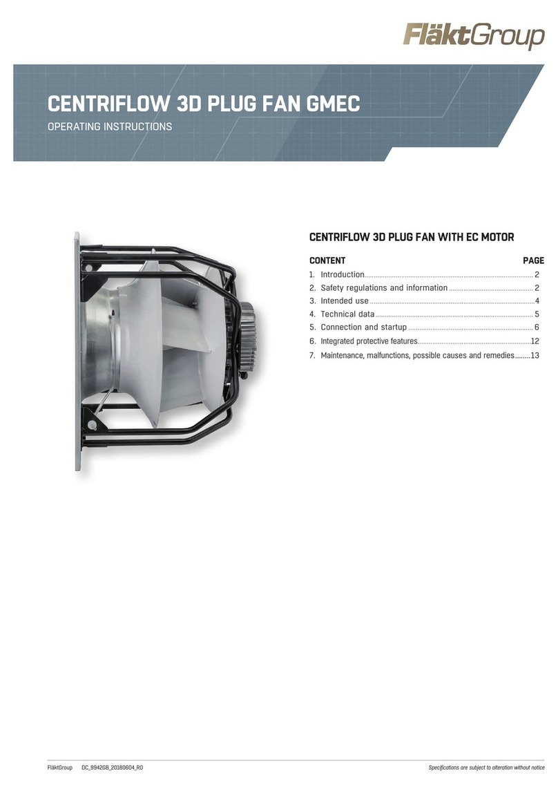
FläktGroup CENTRIFLOW 3D PLUG FAN GMEC User manual

FläktGroup
FläktGroup Roofmaster STEC Series Instruction Manual

FläktGroup
FläktGroup VEKA ver C Instruction Manual

FläktGroup
FläktGroup HYPOWER-GEKO User manual

FläktGroup
FläktGroup LQLR Guide

FläktGroup
FläktGroup GLEC-6 Series Instruction Manual

FläktGroup
FläktGroup ECO SIDE Manual