Flagro FVO-1100TR User manual

OPERATING INSTRUCTIONS MANUAL
(Please retain for future reference)
For
FVO-1100TR INDIRECT FIRED HEATER TRAILER
CERTIFIED FOR USE IN CANADA AND U.S.A.
As per CSA B140.8 Portable Oil Fired Heaters / CSA B140.0 2003 Oil Burning Equipment
UL733 Oil Fired Air Heaters
Construction Heaters Unattended Type.
FLAGRO INDUSTRIES LIMITED
ST. CATHARINES, ONTARIO
CANADA

GENERAL HAZARD WARNING:
FAILURE TO COMPLY WITH THE PRECAUTIONS AND INSTRUCTIONS
PROVIDED WITH THIS HEATER, CAN RESULT IN DEATH, SERIOUS
BODILY INJURY AND PROPERTY LOSS OR DAMAGE FROM HAZARDS OF
FIRE, EXPLOSION, BURN, ASPHYXIATION, CARBON MONOXIDE
POISONING, AND/OR ELECTRICAL SHOCK.
ONLY PERSONS WHO CAN UNDERSTAND AND FOLLOW THE
INSTRUCTIONS SHOULD USE OR SERVICE THIS HEATER.
IF YOU NEED ASSISTANCE OR HEATER INFORMATION SUCH AS AN
INSTRUCTIONS MANUAL, LABELS, ETC. CONTACT THE MANUFACTURER.
WARNING:
FIRE, BURN, INHALATION, AND EXPLOSION HAZARD. KEEP SOLID
COMBUSTIBLES, SUCH AS BUILDING MATERIALS, PAPER OR
CARDBOARD, A SAFE DISTANCE AWAY FROM THE HEATER AS
RECOMMENDED BY THE INSTRUCTIONS. NEVER USE THE HEATER IN
SPACES WHICH DO OR MAY CONTAIN VOLATILE OR AIRBORNE
COMBUSTIBLES, OR PRODUCTS SUCH AS GASOLINE, SOLVENTS, PAINT
THINNER, DUST PARTICLES OR UNKNOWN CHEMICALS.
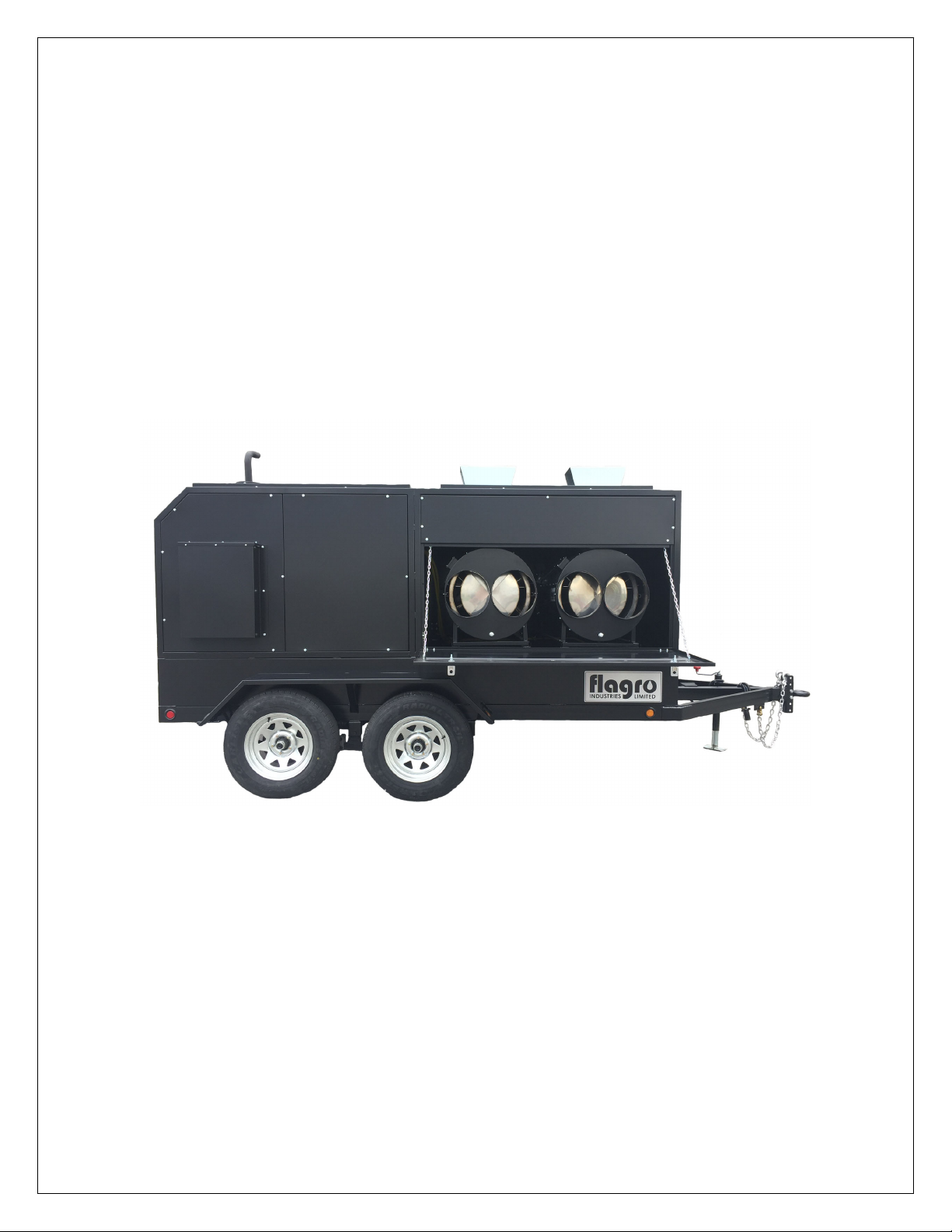
This heater is designed and approved for use as a
construction heater under CSA B140.8 Portable Oil
Fired Heaters / CSA B140.0 2003 Oil Burning Equipment,
UL733 Oil Fired Air Heaters
We cannot anticipate every use which may be made
of our heaters. CHECK WITH YOU LOCAL FIRE
SAFETY AUTHORITY IF YOU HAVE QUESTIONS
ABOUT APPLICATIONS.
Other standards govern the use of fuel gases and heat
producing products in specific applications. Your local
authority can advise you about these

TABLE OF CONTENTS
Trailer Check List…………………………………………………… 4
Towing Instructions…………………………………………………. 5
FVO-1100TR Set-up Procedure……………………………………..6
Set-up Procedure (High Altitude)…………………………………...7,8,9
Nozzle Placement……………………………………………………. 10
Specifications……..………………………………………………….. 11
Trailer Preparation…………………………………………………. 12,13
Heater Start up……………………………………………………… 14
Troubleshooting…………………………………………………….. 15
Heater Maintenance………………………………………………… 16
Feeler Gauge………………………………………………………… 17
Burner Wiring Diagram……………………………………………. 18
Electrode & Oil Line………………………………………………... 19
Trailer Wiring Schematic…………………………………………... 20
Parts List……………………………………………………………..21,22,23

TRAILER CHECK LIST
PLEASE PERFORM THE FOLLOWING STEPS TO YOUR
FVO-1100TR HEATER TRAILER TO ENSURE PROPER OPERATION.
• Visually inspect outside & inside of trailer to ensure all
instructions and decals are in place and legible.
Inspect the tires to ensure road worthy and have proper inflation.
• Inspect hitch assembly and safety tow chains.
• Inspect jack assembly to make sure it operates properly.
• Make sure all trailer cabinet doors are closed before attempting to
relocate trailer.
• Check lug nuts and torque to 80-90 ft. lbs. Lug nuts should be re-
torqued every 100 miles.
• Check oil, fuel and coolant levels on genset.
• Make sure brake & signal lights on trailer are completely
operational.
• Make sure the battery is fully charged and the terminals are tight.
• Start engine and heaters to ensure proper operation.
• Review engine manual for maintenance requirements.

TOWING INSTRUCTIONS
Before towing the FVO-1100TR, please make sure you go over
the following steps to ensure your trailer is road ready.
1. Hitch is securely attached to towing vehicle.
2. Safety chains are securely attached to towing vehicle.
3. Front jack is completely retracted.
4. Check all tires ensure they have adequate air pressure.
5. Make sure all ducting is removed from heaters.
6. All doors are closed and secure.
7. Taillights are connected and operating.
1
2 3
4
5
6
7
6

FVO-1100TR SETUP PROCEDURE
The two FVO-400RC heaters in the trailer need to be tested and set up
before every operation. Proper combustion must be achieved using a
certified combustion analyzer and smoke gun tester to ensure optimum
set up. The air adjustment should be made to achieve a maximum of
10% CO2 and No. 1 or “trace” smoke. (Bacharach Scale)
SETTING THE AIR ADJUSTMENT PLATE
A) Regulation of the
combustion air flow is made
by adjustment of the manual
AIR ADJUSTMENT PLATE
(1) after loosening the FIXING
SCREWS (2 & 3). The initial
setting of the air adjustment
plate is set to 4.5 at the
factory.
B) The proper number on the
manual AIR ADJUSTMENT
PLATE (1) should line up with
the SETTING INDICATOR (4)
on the fan housing cover.
Once set, the air adjustment
plate should be secured in
place by tightening SCREWS
2 and 3.
C) The final position of the air
adjustment plate will vary on
each installation. Use instruments to establish the proper settings for maximum
CO2 and a smoke reading of zero.
NOTE: Variations in flue gas, smoke, CO2 and temperature readings may be
experienced when the burner cover is put in place. Therefore, the burner
cover must be in place when making the final combustion instrument readings,
to ensure proper test results.

SETUP PROCEDURE (HIGH ALTITUDE)
When the FVO-1100TR is required to operate over 2000 feet above sea
level there will be necessary adjustments needed to burn efficiently with
thinner air. Please review the following chart as a starting point; please
note that a combustion analyzer & smoke gun will be required to
achieve optimum set up.
ACTUAL
FIRING RATE
+/- 5%
NOZZLE
SIZE
PUMP
PRESSURE
TURBULATOR
SETTING
AIR DAMPER
SETTING
ALTITUDE
RANGE
2.11 GPH 1.75 X 60W 145 PSI 2.5 3.1 OVER
7000FT
2.41 GPH 2.00 X 60W 170 PSI 3.5 3.4 3500-6900FT
2.61 GPH 2.00 X 60W 170 PSI 5.0 4.5 0-3500FT
Please refer to the Air adjustment plate diagram on page 6, the
turbulator diagram at the bottom of this page & the nozzle replacement
diagram on page 8.
NOTE: The burners are equipped with a 2.00 X 60W nozzle, due to the
increase density of oil/diesel fuel at colder temperatures.
TURBULATOR SETTING
A) Loosen NUT (1), then turn SCREW (2) until the INDEX MARKER (3) is
aligned with the correct index number as per the Burner Set-up chart
above.
B) Retighten the RETAINING NUT (1)
NOTE: Zero and five are scale indicators only. From left to right, the first
line is 5 and the last line 0.

INSERTION / REMOVAL OF DRAWER ASSEMBLY
A) To remove drawer assembly, loosen SCREW (3), then unplug
CONTROL BOX (1) by carefully pulling it back and then up.
B) Remove the AIR TUBE COVER PLATE (5) by loosening the two
retaining SCREWS (4).
C) Loosen SCREW (2), and then slide the complete drawer assembly out
of the combustion head as shown.
D) To insert drawer assembly, reverse the procedure in items A to C above,
and then attach fuel line to the pump.

NOZZLE PLACEMENT
A) Remove the NOZZLE ADAPTER (2) from the DRAWER ASSEMBLY by
loosening the SCREW (1).
B) Insert the proper NOZZLE into the NOZZLE ADAPTER and tighten
securely (Do not over tighten).
C) Replace adapter, with nozzle installed, into drawer assembly and secure
with screw (1).

SPECIFICATIONS
Model …………………………… FVO-1100TR
Input ……………………………... 390,000 BTU x 2 @ 2.61 GPH
Engine …………………………… Kubota Liquid Cooled Diesel
Electric start/ glow plugs
Battery charging alternator
Heavy duty Radiator & Air Cleaner
Remote Oil Drain
Generator………………………… 8 kw @ 1800 rpm (15.4 HP)
Single phase-120V
Instrument panel including Hour Meter
Fuel …………………………….... No.1, No. 2, Diesel
Fuel Pressure ………………..........170 psi @ 0-2000 ft
Nozzle …………………………… 2.00 x 60W (Delavan) @ 0-2000 ft
Fuel Tank ……………………….. 1,132 Liters / 300 Gallons
Heavy duty fuel sight gauge
2” Fuel inlet nozzle
Power Tool Outlet ………………. 1 x 15 Amp GFI Outlet
Ignition ………………………….. Direct Spark Ignition
Fan Motor…………………………1- HP @ 1750 RPM
Air Circulation ………………….. 8000 CFM (4000 PER HEATER)
Fuel Consumption ………………. 6.07 GPH at full load
Dimensions………………………. Height-7ft, Length-16ft, Width-7ft 4 inches
Weight……………………………. 4,300 lbs (Empty)
Approvals ……………………….. cETLus listed (Heaters)
CSA/ Entela approved (Engine/Generator)
DOT approved trailer

TRAILER PREPARATION FOR START-UP
PLEASE REVIEW TRAILER CHECKLIST, FVO-1100TR SETUP &
GENERATOR MANUAL BEFOR PROCEEDING
OPEN REAR GENERATOR
ACCESS DOORS
OPEN HEATER OUTLET DOOR

MAKE SURE BATTERY LOCK
OUT IS TURNED OFF, AND
TURN KEY ON CONTROL
PANEL TO START
OPEN HEATER DOORS &
START UP HEATERS
INSPECT FUEL GAUGE FOR
SUFFICIENT LEVEL OF FUEL

HEATER START UP INSTRUCTIONS:
1. Open heater inlet doors; verify that each heater toggle “switch” is in the
“OFF” position.
2. Attach ducting to outlet duct adapters, if required
3. Start generator
4. Start heaters by moving the toggle switch to “MANUAL” position for
manual control.
OR
5. Move toggle switch to “THERMOSTAT” position for thermostatic
control.
Please Note:
1. If using Thermostat on unit, unit must be started in Thermostat position.
2 When changing between manual and thermostat operation, the heater
must be left in the “OFF” position for 30 seconds to prevent the burner
from locking out.
3. If the generator runs out of fuel, make sure the heater switch is in the
“OFF” position before restarting generator, failure to do so may damage
heater.
TO SHUT DOWN:
1. Move heater toggle switch to “OFF” position.
NOTE: Fan will continue to operate after the burner shuts off . Once the
unit cools down, the fan will stop.
Never pull power plug to shut unit down, if power plug is pulled ignition
box may be damaged, and will not be covered under warranty.
DO NOT TURN GENERATOR OFF UNTIL HEATERS HAVE COOL DOWN

IF HEATER FAILS TO START:
1. Press manual reset button at rear of burner. (Red button)
2. Check fuel level gauge for sufficient amount of fuel.
3. Make sure there are no air blocks in fuel lines or filter. Bleed lines if
required.
4. Ensure power supply plug is connected properly.
5. Check for dirty fuel filter or blocked fuel supply line.
6. Check burner nozzle assembly.
7. Make sure the burner control box does not need to be reset.
NOTE: IF THE BURNER HAS BEEN RESET SEVERAL TIMES THERE
MAY BE AN ACCUMULATION OF FUEL IN THE CHAMBER! DO NOT
CONTINUE TO TRY AND START THE HEATER!
DRAIN FUEL FROM HEAT EXCHANGER USING DRAIN HOLE AT FRONT
OF HEAT EXCHANGER FOR 15-20 MINUTES BEFORE ATTEMPTING TO
RELIGHT. LET REMAINING EXCESS FUEL BURN OFF BEFORE
CHECKING COMBUSTION OF UNIT.
SAFE OPERATION PRECAUTIONS:
1. Do not fill fuel tank while heater is operation.
2. Do not attempt to start heater if excess oil remains in the heat
exchanger.
3. Use switch to shut down the heater. Do not try to shut down the heater
by unplugging the electrical cord.
4. Do not plug anything other that the thermostat into the “Thermostat”
plug.
5. Do not use any fuel other that those listed on rating plate.
6. Before removing any guards or performing any maintenance, be sure
that the main power supply is disconnected.

MAINTENANCE:
1. Every construction heater should be inspected before each use, and at
least annually by a qualified service person. Incorrect maintenance my
result in improper operation of the heater and serious injury could
occur.
2. The hose assemblies shall be visually inspected prior to each use of the
heater. If it is evident there is excessive abrasion or wear, or the hose is cut, it
must be replaced prior to the heater being put into operation. The
replacement hose assembly shall be that specified by the manufacturer.
3. The flow of combustion and ventilation air must not be obstructed. Be sure to
check the fan assembly and ensure that the motor and blade are operating
properly.
4. Compressed air should be used to keep components free of dust and dirt
build up. Note: Do not use the compressed air inside any piping or regulator
components.
5. Change fuel filter insert (Part# FVO-TLSF) once year.
6. Change oil burner nozzle (Part# FV-435B (2.00 X 60) once per year.
7. Fan Limit Switch (Part# FV-407A) should be replaced if the fan motor does
not shut off after the heat exchanger has cooled down.
8. The High Limit Switches (Part# FV-406 & FV-437) should be checked each
season. These limit switches will ensure the burner shuts down if the
temperature exceeds 150º F at rear of unit and 250º F at the outlet.
9. Fuel tank should be drained on a regular basis by removing drain plug.
10. CAUTION – Do not have any source of ignition near the heater when
draining tank.
NOTE: No.1 fuel oil or kerosene is recommended for temperatures below
-10º C / 8º F.
11. Heat Exchanger should be cleaned if smokey conditions continue even after
the air adjustments on the burner are made.

TEMPERATURE FEELER GAUGE ADJUSTMENT
(ATTACHED TO FAN SWITCH)
The temperature feeler gauge is required to be always touching the heater
exchanger.
The temperature feeler gauge controls the air flow over the fan switch, which
eliminates any unnecessary fan cycling. The temperature feeler gauge can be
adjusted for different outside temperatures, by rotating the location of the
temperature feeler gauge holes. This will provide maximum performance of the
unit in different applications.
If supply air is warm (-5º C, indoor application):
Turn the temperature feeler gauge so that the holes are parallel with the heat
exchanger. This will help the fan switch to remain cool and not overheat. See
following:
If supply air is cold (under -5ºC):
Turn the temperature feeler gauge so that the holes are closed off as the air goes
over the heat exchanger. This will reduce fan cycling and the unit from shutting
down. See following:
In extreme cold conditions, cover the holes on the temperature feeler gauge
using foil tape or use part# FV-433B (solid feeler gauge). Ensure that the
temperature feeler gauge is readjusted for warmer weather conditions. Failure to
do so may result in burning out fan switches- not covered under warranty.

BURNER WIRING DIAGRAM
ELECTRICAL CONNECTIONS
It is advisable to leave the control box off the sub-base while completing the
electrical connections to the burner.

ELECTRODE SETTING
OIL LINE CONNECTIONS
Note: Pump pressure must be set at time of burner start-up. A pressure gauge
is attached to the PRESSURE PORT (8) for pressure readings. Two PIPE
CONNECTORS (5) are supplied with the burner for connection to either a single
or a two-pipe system. Also supplied are two ADAPTORS (3), two female 1/4”
NPT, to adapt oil lines to burner pipe connectors. All pump port threads are
British Parallel Thread design. Direct connection of NPT threads to the pump will
damage the pump body. Riello manometers and vacuum gauges do not require
any adaptors, and can be safely connected to the pump ports. An NPT (metric)
adapter must be used when connecting other gauge models.

FVO-437TR
FVO-1100TR – PARTS LIST
HARDWARE
FMA-2312
DOOR LATCH
FV-450TR
BOLT ON HINGE
FV-443TR
PUSH TO CLOSE
FV-465TR
LOCKING DOOR LATCH/ ROD BALL HITCH
FVO-438TR
PINTLE HITCH
FVO-435TR
SUPPORT JACK
FV-EBK
EMERGENCY BREAKAWAY KIT

FVO-439TR
FV-464TR/FV-463TR
FVO-436TR
FV-460TR/FV-461TR
FV-457TR
LICENSE PLATE LIGHT SAFETY CHAINS (set)
VENT DEFLECTOR/
VENT PIPE TAILPIPE
FV-458TR/FV-459TR
MUFFLER & FLEX PIPE
OIL TANK CAP C/W CHAIN
(TC Approved)
BATTERY & TRAY/HARNESS
FVO-416AGTR-1
OIL TANK FUEL GAUGE
(TC APPROVED) BATTERY LOCK-OFF SWITCH
FV-462TR
FVO-417TR-1
Table of contents
Other Flagro Utility Vehicle manuals
Popular Utility Vehicle manuals by other brands

PRONAR
PRONAR T680 Operator's manual

Yamaha
Yamaha Wolverine YX70EPNG Service manual

Taylor-Dunn
Taylor-Dunn C0-425-36 Operation, troubleshooting and replacement parts manualooting and replacement parts manual

Cushman
Cushman 646442 owner's manual

All Traffic Solutions
All Traffic Solutions ATS 3 quick start guide

Hammerhead
Hammerhead SS250 Technical manual