flakt woods CURO Touch Owner's manual

AIR TREATMENT
CONTROL EQUIPMENT
AIR COMFORT LCD CONTROL PANEL
CURO®TOUCH FOR ECOSTAR
» Technical insTrucTion for version 2.02
APRIL 2015


Curo
®
Touch - Technical Instruction Version 2.02
Fläkt Woods 9401 GB 2015.04.07 Specifications are subject to alteration without notice
3
NOTE: THE INSTALLATION, ADJUSTMENT AND COMMISSIONING DESCRIBED WITHIN
THIS MANUAL MUST BE CARRIED OUT BY THE INSTALLER, OR SERVICE PERSONNEL.
CONTENTS
WARNING: This appliance is not intended for use by persons (including children) with reduced
physical, sensory or mental capabilities, or lack of experience and knowledge, unless they have
been given supervision or instruction concerning use of the appliance by a person responsible for
their safety. Children should be supervised to ensure that they do not play with the appliance.
INSTALLATION INSTRUCTIONS
Installation & Connection................................................................................................................................... 4
USER INSTRUCTIONS
Introduction, Conventions & Using the unit................................................................................................5
Home Screen overview......................................................................................................................................6
Basic Operation, overview................................................................................................................................. 7
Operating modes, Alarms & User settings................................................................................................8
COMMISSIONING INSTRUCTIONS
Settings of date/time, language.....................................................................................................................9
Advanced settings.............................................................................................................................................. 10
Commissioning Wizard.....................................................................................................................................11
Schedules .............................................................................................................................................................. 12
Timer function....................................................................................................................................................... 14

Curo
®
Touch - Technical Instruction Version 2.02
Fläkt Woods 9401 GB 2015.04.07 Specifications are subject to alteration without notice
4
INSTALLATION & CONNECTION OF LCD CONTROL PANEL CURO®TOUCH
1. Open the control panel using a screwdriver
2. Lift the display out of the enclosure.
4. Push the connection cable through a suitable hole and if
needed make an outlet for the cable on side of the cover.
Mount the enclosure directly on the wall.
5. Push back the display in the enclosure.
3. Connect the cable to the back of the display as shown above.
Note. Please do not touch the electronics.

Curo
®
Touch - Technical Instruction Version 2.02
Fläkt Woods 9401 GB 2015.04.07 Specifications are subject to alteration without notice
5
INTRODUCTION, CONVENTIONS & USING THE UNIT
INTRODUCTION
HMI
This section provides an introduction to the touchscreen LCD
control panel, also known as the ‘Human Machine Interface’, or
simply, HMI.
The HMI serves two main purposes: To provide information about
the current operational state of the unit. To allow the unit to be
setup and configured.
TOUCH SCREEN TIPS
To select an item, touch the center of the icon or option. Do not
press too hard, the touch screen is sensitive enough to pick up
light, firm touches. Use the tip of your finger or the back of a pen-
cil to touch the required option. Be careful not to touch any other
options.
CLEANING THE SCREEN
Disconnect the power cord. Gently wipe the screen with a soft,
dry non-abrasive cloth. If the marks remain, moisten the cloth
slightly with a detergent that is designed for LCD or mobile
screens and wipe the screen gently from top to bottom. Never
use detergents, as these may contain ammonia or other additives.
IMPORTANT:
• Never spray, or pour liquids directly on to the screen.
• Do not clean the screen while the system is on.
CONVENTIONS USED WITHIN THIS MANUAL
The following buttons and symbols are universal and available on
many menu pages.
Home key, to return to the Home Screen.
Back button, to cancel and return to the previous
page.
Confirm button to confirm and proceed.
Changing a value:
Option 1: Press the arrow keys to increase or
decrease the value.
Option 2: Press the displayed number to
numerically adjust the value.
USING THE UNIT
POWERING ON
Each time power is applied, the unit will run through a series of
internal system tests which take approximately 20 seconds to
complete.
Once the internal system tests have been completed, the HMI will
always display the Home screen. The unit will be in Manual Mode
the first time that power is applied.
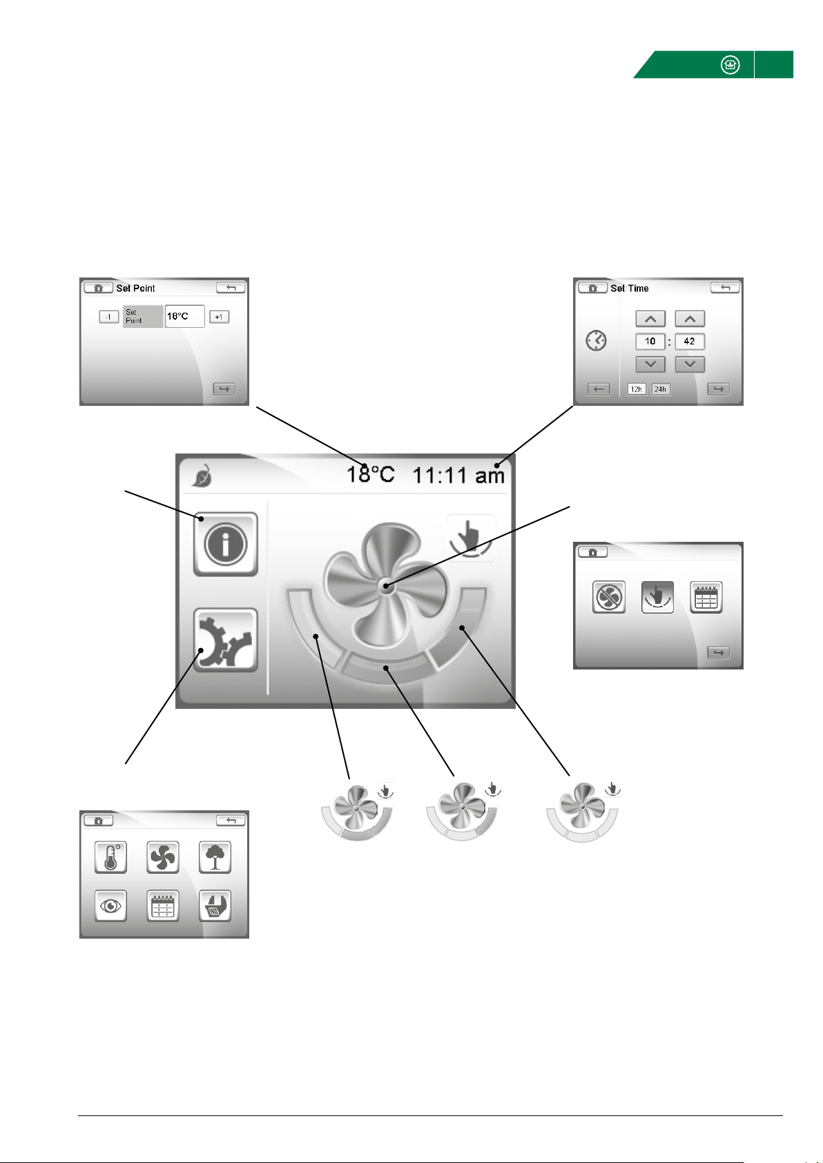
HOME SCREEN
The unit always powers up in the Home screen. From the Home
screen it is possible to determine how the unit is operating as
well as navigating to further screens to configure the unit to suit
the demands of the end system.
From the Home Screen, it is possible to:
Navigate to further configuration screens to setup system param-
eters.
• Manually adjust the fan speed.
• Determine the operating status of the product.
• Interrogate and acknowledge system alarms.
Use the number buttons to enter
a value.
Confirm with or cancel with .
Values that can only be read, but not written,
are displayed without a surrounding window.
Values that can be both read and written,
are displayed with a surrounding window.
Some submenus has several
pages. Touch the upper or the
lower part of the scroll list to
navigate between pages.

Curo
®
Touch - Technical Instruction Version 2.02
Fläkt Woods 9401 GB 2015.04.07 Specifications are subject to alteration without notice
6
HOME SCREEN OVERVIEW
ALARM
No alarm
Alarm B
Alarm A
Heat recovery active
Post-heater active
Pre-heater active
Cooling active
Defrosting in progress
Manual mode
CO
2
regulation
Automatic mode
Constant pressure
Timer 1
Timer 2
Timer 1/Timer 2
Trickle or low speed
Normal or medium speed
Boost or high speed
STATUS LINE
OPERATING STATUS
OPERATING MODES
CLOCK
CURRENT SET POINT
TEMPERATURE
COP
Curo
®
Touch - Technical Instruction Version 2.02
Fläkt Woods 9401 GB 2015.04.07 Specifications are subject to alteration without notice
7
ALARM
See page 8.
BASIC OPERATION OVERVIEW
SHORTCUT TO SET THE
TEMPERATURE SET POINT
USER SETTINGS
See page 8.
SHORTCUT TO SET THE TIME
AND DATE
SELECT OPERATING MODE
See page 8.
TRICKLE OR
LOW SPEED
NORMAL OR
MEDIUM SPEED
BOOST OR
HIGH SPEED
Press each field to select the operating mode.
Only active in Manual Mode.
Curo
®
Touch - Technical Instruction Version 2.02
Fläkt Woods 9401 GB 2015.04.07 Specifications are subject to alteration without notice
8
OPERATING MODES
The operating status icon present on the Home Screen dis-
plays the current operating mode. To change the operating
mode, press the large fan icon located on the Home Screen.
The unit has three operating modes selectable through the
Operating Modes screen:
Stop Mode: In this mode, the unit will stop both the
supply and the extract fans.
Manual Mode: In this mode, the unit can be manually
adjusted on the Home Screen to run at three different
speeds.
Automatic Mode: In this mode, the unit will be automa-
tically controlled using internal schedules and timers,
CO
2
demand control, PIR sensors, etc.
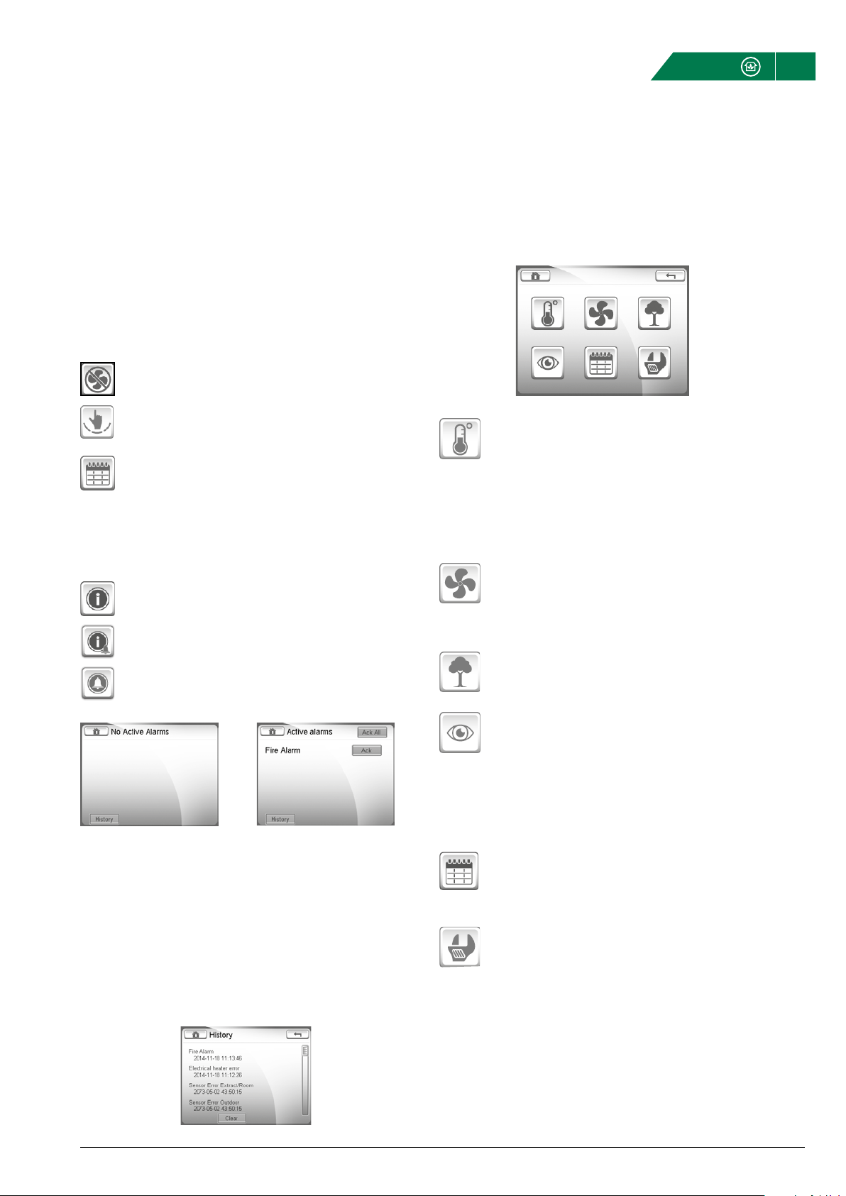
ALARM SCREEN
The alarm icon on the Home Screen indicates the status of any
system alarms:
No alarm
Alarm type B are deemed non-critical
and do not stop the unit ventilation.
Alarm type A are deemed critical and will
cause the unit to stop ventilating.
Press the icon to enter the Alarm Screen.
USER SETTINGS
OPERATING MODES, ALARMS & USER SETTINGS
TEMPERATURE STATUS
The temperature set point is used to determine when
the post-heater (if fitted) starts to warm the supply air
entering the property. The temperature set point can be
adjusted to any temperature between 15° C and 35° C,
factory setting is 18° C.
Temperatures and output signals are read only values.
FAN STATUS
From the Fan Control Status screen it will be possible
to view parameters such as supply and extract fan
speeds, %, off and pressures.
AIR QUALITY
CO
2
value and CO
2
set point (if activated).
SYSTEM OVERVIEW
Version Control Panel IP Octet 1
Bootloader Control Panel IP Octet 2
Version Control Card IP Octet 3
Bootloader Control Card IP Octet 4
Unit type
SCHEDULES
Read only. For more information see section ”Schedules”
on page 21.
ADVANCED SETTINGS
See section ”Advanced settings” on page 10.
Example 1: No alarm Example 2: Active alarms
CLEARING ALARMS
To clear an individual alarm, press the Ack button. To clear all the
Alarms press the Ack All button on top of the screen.
It may not always be possible to clear the status of an alarm as the
source of the alarm may immediately trigger the status to return.
For example, it will not be possible to clear a faulty temperature
sensor alarm until the sensor itself has been repaired or replaced.
Alarm B
Alarm A
ALARM HISTORY

Curo
®
Touch - Technical Instruction Version 2.02
Fläkt Woods 9401 GB 2015.04.07 Specifications are subject to alteration without notice
9
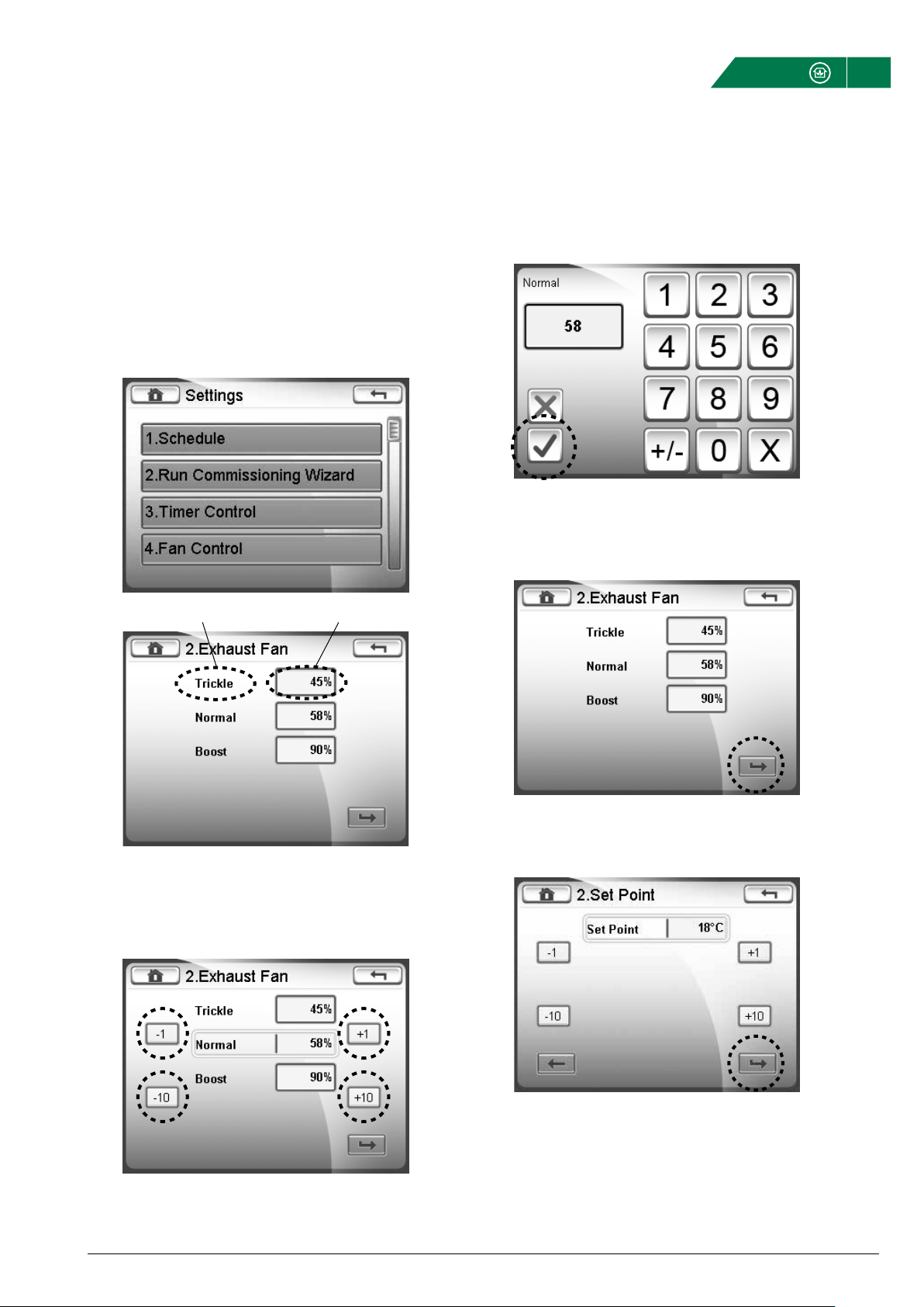
CONFIGURING LANGUAGE, DATE & TIME
SETTINGS
To enter the settings menu:
1. Push on the gear cog button.
2. Push the spanner button.
3. In this menu you set the date, time and language. It is also
possible for installers and service personnel to log in and
access additional parameters.
DATE/TIME
2 Set the time and press the Confirm button
1. Set the date and press the Confirm button.
CHOOSE LANGUAGE
1. Choose the appropriate language flag and press
the Confirm button.
Note, further language flags are available after
pressing the right arrow icon.

Curo
®
Touch - Technical Instruction Version 2.02
Fläkt Woods 9401 GB 2015.04.07 Specifications are subject to alteration without notice
10
ADVANCED SETTINGS
LOGIN
Advanced settings requires the Login passcode, 0000, to be
entered.
1. Enter the correct passcode and press the Confirm button.
SETTINGS FOR INSTALLER AND SERVICE PERSONNEL
This section provides an overview to the more advanced opera-
tions that are available from the Home Screen via the passcode
protected Advanced Settings option.
Numerous system parameters can be adjusted through the
Settings Screen; however, only those that are relevant and appro-
priate to the scope of the HMI User Manual will be described. It
is strongly recommended to avoid the adjustment of any system
parameters not outline within this section.
Access to the Settings Screen is passcode protected to prevent
system critical parameters from being accidentally adjusted to
values that could compromise the correct operation of the unit.
Therefore, extreme caution should be observed when adjusting
Advanced Settings parameters.
Curo
®
Touch - Technical Instruction Version 2.02
Fläkt Woods 9401 GB 2015.04.07 Specifications are subject to alteration without notice
11
COMMISSIONING WIZARD
OPTION 1 - Press Trickle, Normal, Boost, then use the
±1 or ±10 buttons.
OPTION 2 - Press the values within the boxes adjacent to Trickle,
Normal, or Boost, then use the numerical keypad.
OPTION 1
OPTION 2
When completed, press the Confirm button to proceed to the
supply fan.
Make the appropriate settings for the supply fan and press the
Confirm button.
OPTION 1 OPTION 2
Adjust the supply air temperature set point in ° C and press the
Confirm button to complete the Commissioning Wizard.
Note, whilst in the Commissiong Wizard, the Back button can be
pressed at any time to access the previous page of settings.
The Commissioning Wizard allows the basic unit settings to be
configured in a simple and intuitive manner.
The Commissioning Wizard is accessed by selection the ”Run
Commissioning Wizard” option from the advanced settings screen.
The speeds for each operation mode can be changed in two ways:
Curo
®
Touch - Technical Instruction Version 2.02
Fläkt Woods 9401 GB 2015.04.07 Specifications are subject to alteration without notice
12
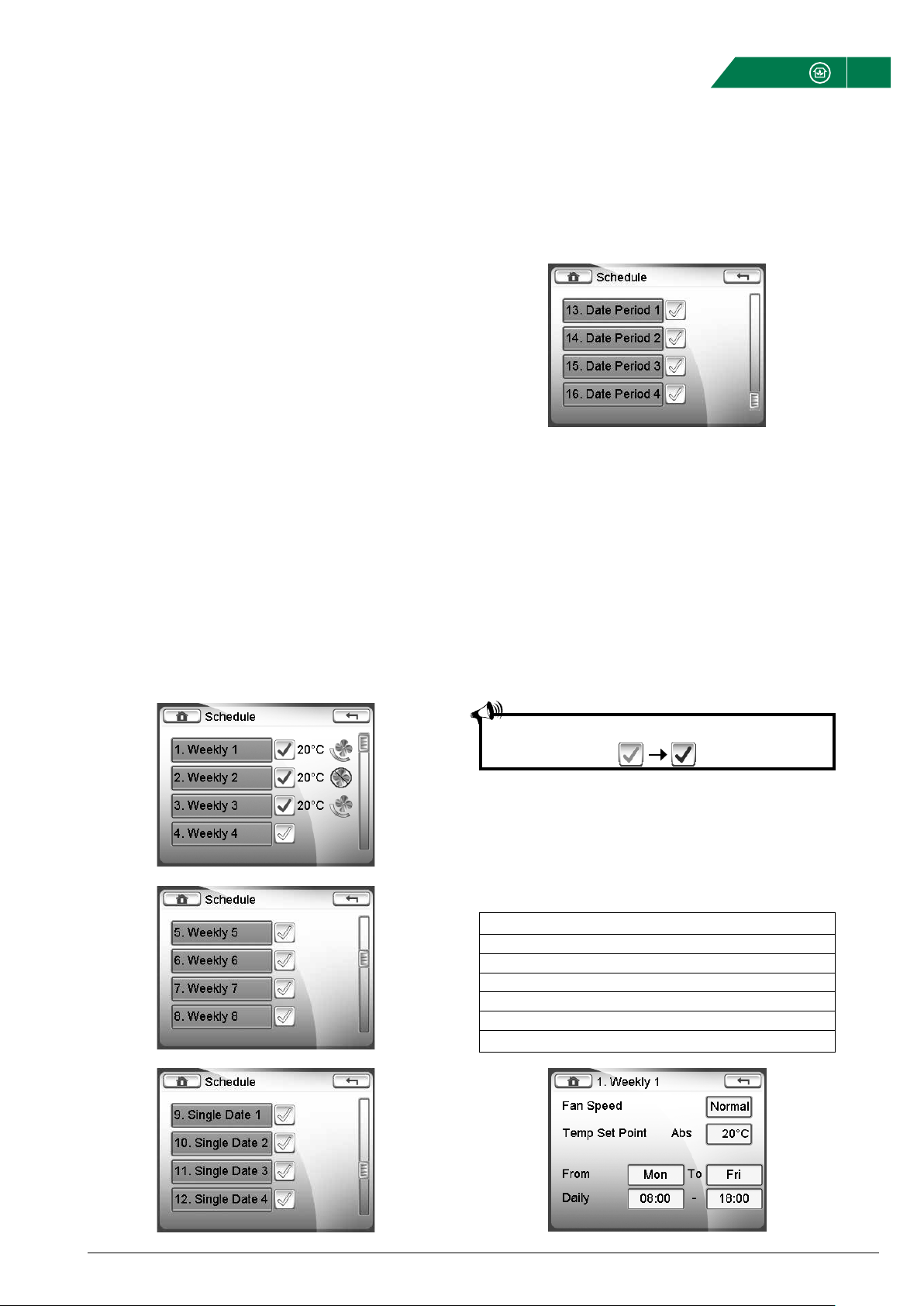
SCHEDULES
EXAMPLE 1 - WEEKLY SCHEDULE
Below is an example of a weekly schedule configured to run the
fans at normal speed from 08:00 to 18:00 Monday to Friday. At
all other times, the fans are turned off.
If a post heater has been fitted, this will maintain the supply air
temperature at 20°C.
Day Time Fan Speed Temp Setpoint
Monday 8-18 Normal 20 °C
Tuesday 8-18 Normal 20 °C
Wednesday 8-18 Normal 20 °C
Thursday 8-18 Normal 20 °C
Friday 8-18 Normal 20 °C
Other time Stop
SCHEDULES
Using schedules, it is possible to fully automate the unit to pro-
vide specific levels of ventilation at specific times of the day,
week or year and to activate the post-heater at a given tempera-
ture set point.
To activate schedules, the unit has to be in Automatic mode.
Each schedule also needs to be activated by pressing the grey
tick button.
WEEKLY (1-8)
Pressing this option selects the Weekly Schedule adjustment
screen to create a timed schedule to run daily in a week.
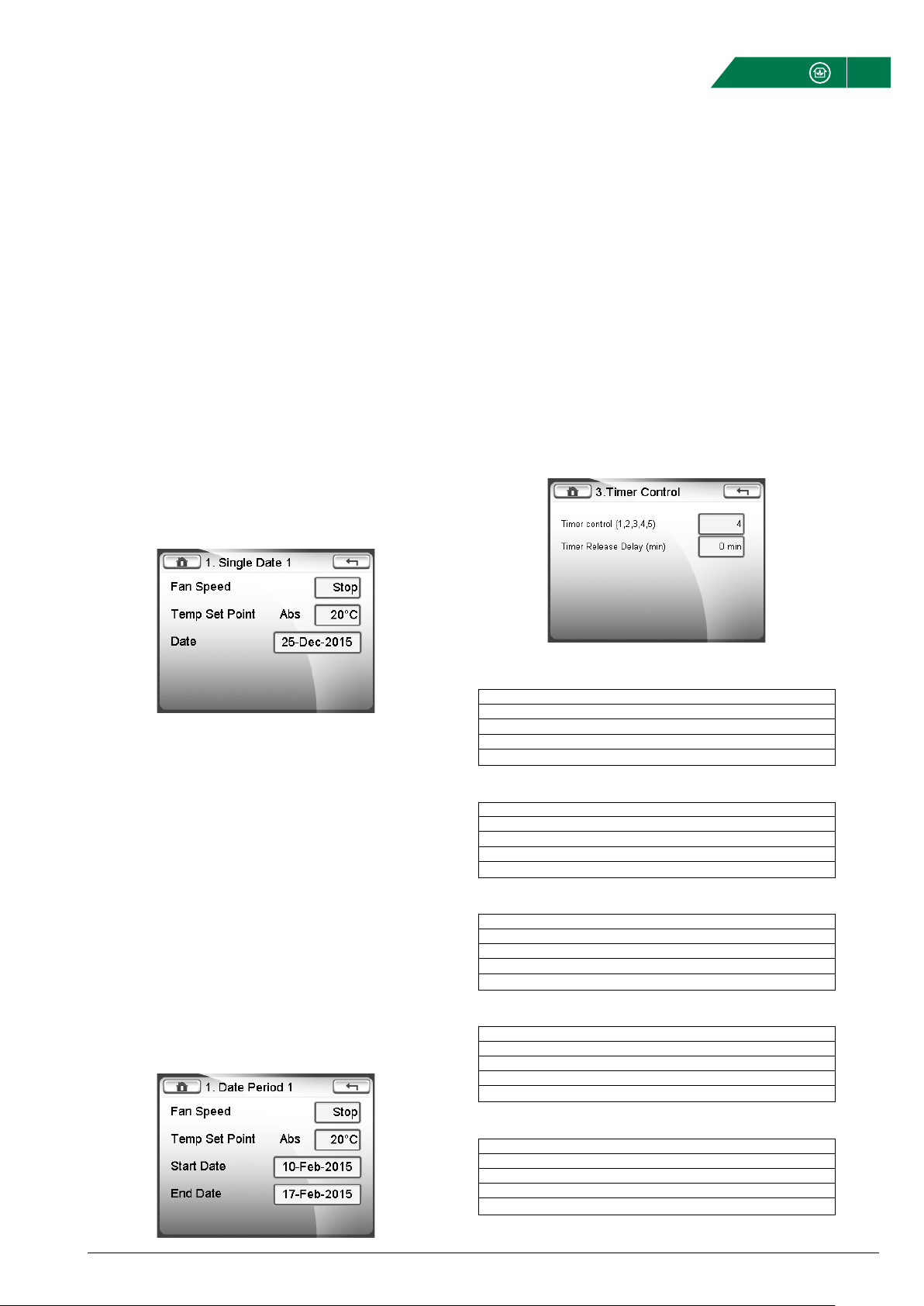
SINGLE DATE (1-4)
Pressing this option selects the Single Date Schedule adjustment
screen to create a timed schedule to run for 24 hours on any
single date.
DATE PERIOD (1-4)
Pressing this option selects the Date Period Schedule adjustment
screen to create a timed schedule to run from any date to any
other date.
WEEKLY SCHEDULE
A weekly schedule is defined as a schedule that automatically
runs from a given time to a given time on specified days.
During a weekly schedule, the fans can be set to run at any of the
available speeds: Stop, trickle, normal or Boost.
The eight individual weekly schedules are prioritized to remove
the potential for time periods to clash with each other. Weekly
8 Schedule has the highest priority and Weekly 1 Schedule the
lowest priority. If two or more weekly schedules have start and
end times that clash with each other, only the schedule with the
highest priority will be used, the other(s) will be ignored.
The supply and extract fans will run at the same speed when set-
up through a weekly schedule.
Remember to activate the desired schedules by pressing

Curo
®
Touch - Technical Instruction Version 2.02
Fläkt Woods 9401 GB 2015.04.07 Specifications are subject to alteration without notice
13
EXAMPLE 2 - WEEKLY SCHEDULE
Below is an example of a weekly schedule configured to run the
fans at normal speed from 08:00 to 18:00 Monday to Thursday,
from 08:00 to 17:00 on Friday and 10:00 to 14:00 on Saturday. At
all other times, the fans are turned off.
If a post heater has been fitted, this will maintain the supply air
temperature at 20°C.
Day Time Fan Speed Temp Setpoint
Monday 8-18 Normal 20 °C
Tuesday 8-18 Normal 20 °C
Wednesday 8-18 Normal 20 °C
Thursday 8-18 Normal 20 °C
Friday 8-17 Normal 20 °C
Saturday 10-14 Normal 20 °C
Other time Stop
SCHEDULES (CONT)
EXAMPLE 3 - WEEKLY SCHEDULE
Below is an example of a weekly schedule configured to run the
fans at normal speed from 08:00 to 18:00 Monday to Friday. At all
other times, the fans are configured to run at trickle speed. Note,
this schedule uses the higher priority of Weekly 2 schedule to
over-ride Weekly 1 schedule during the Monday to Friday normal
speed periods.
If a post heater has been fitted, this will maintain the supply air
temperature at 20°C from 08:00 to 18:00 Monday to Friday and at
18°C at all other times.
Day Time Fan Speed Temp Setpoint
Monday 8-18 Normal 20 °C
Tuesday 8-18 Normal 20 °C
Wednesday 8-18 Normal 20 °C
Thursday 8-18 Normal 20 °C
Friday 8-18 Normal 20 °C
Other time Trickle (Low) 18 °C
Curo
®
Touch - Technical Instruction Version 2.02
Fläkt Woods 9401 GB 2015.04.07 Specifications are subject to alteration without notice
14
TIMER FUNCTION 1
Timer 1 Timer 2
Manual/Automatic Mode 0 0
Trickle 1 0
Normal 0 1
Boost 1 1
TIMER FUNCTION 2
Timer 1 Timer 2
Manual/Automatic Mode 0 0
Trickle 1 0
Boost 0 1
Stop 1 1
TIMER FUNCTION 3
Timer 1 Timer 2
Manual/Automatic Mode 0 0
Normal 1 0
Boost 0 1
Stop 1 1
TIMER FUNCTION 4 (DEFAULT)
Timer 1 Timer 2
Stop 0 0
Manual/Automatic Mode 1 0
Stop 0 1
Boost 1 1
TIMER FUNCTION 5
Timer 1 Timer 2
Stop 0 0
Manual/Automatic Mode 1 0
Stop 0 1
Normal 1 1
SCHEDULES (CONT) & TIMER FUNCTION
A single date schedule can be cancelled by setting the schedule
date to any date earlier than the current date.
A single date period schedule can be cancelled by setting both
the From and To schedule dates to any date earlier than the cur-
rent date.
DATE PERIOD SCHEDULE
A date period schedule is defined as a one-off schedule that is
configured to run between any to dates, staring at 00:00:00 on
the first date and finishing at 23:59:59 on a second date.
During a weekly schedule, the fans can be set to run at any of the
available speeds: Stop, trickle, normal or Boost.
The four individual date period schedules are prioritized to
remove the potential for time periods to clash with each other.
Date Period 4 Schedule has the highest priority and Date Period 1
Schedule the lowest priority. If two or more date period schedules
have start and end times that clash with each other, only the
schedule with the highest priority will be used, the other(s) will be
ignored.
The supply and extract fans will run at the same speed when
setup through a date period schedule.
SINGLE DATE SCHEDULE
A single date schedule is defined as a one-off schedule that
automatically starts and finishes on the same date and runs for
the whole day, i e, from 00:00:00 to 23:59:59.
During a single date schedule, the fans can be set to run at any
of the available speeds: Stop, trickle, normal or Boost.
The four individual single date schedules are prioritized to remove
the potential for time periods to clash with each other. Single
Date 4 Schedule has the highest priority and Single Date 1 Sched-
ule the lowest priority. If two or more single date schedules have
start and end times that clash with each other, only the schedule
with the highest priority will be used, the other(s) will be ignored.
The supply and extract fans will run at the same speed when set-
up through a single date schedule.
TIMER CONTROL
The Timer Control setting determines what speed the fans will
run at when up to two external, volt-free switches are applied to
the TM1 and PIR terminals - refer to page 12 for customer wiring
options.
A ’0’ in the tables below indicates a volt-free open-circuit input
and ’1’ indicates a volt-free short-circuit input.


FWG-Curo® Touch Technical instruction-GB-2015.04.07 9401GB © Copyright 2015 Fläkt Woods Group
WWW.FLAKTWOODS.COM CURO® TOUCH v 2.02 | 9401GB | 20150407
We bring
BETTER AIR™
to life
» To learn more about our offering and get in contact with your
nearest sales representative please visit www.flaktwoods.com
With over a century of innovation and expertise to share with our
customers, Fläkt Woods is a global leader in Air Technology products
and solutions. We specialize in the design and manufacturing of a
wide range of products and solutions for Air Movement, Air Treatment,
Air Distribution, Air Management and Air Diffusion with focus on two
major benefits – Air Comfort and Fire Safety. With market presence
in 65 countries we are in a unique position to be a local supplier
and an international partner in our customer’s projects.
Our product brands such as SEMCO
®
, eQ
®
, eQ Prime
®
, JM Aerofoil
®
,
Econet
®
, Veloduct
®
, Optivent
®
, Optimix
®
, Econovent
®
and Clean-
vent
®
are well-known and trusted by customers all over the world
to deliver high quality and energy efficient solutions.
Table of contents
Popular Control Panel manuals by other brands

ROEL
ROEL CERBER C52 Installation and programming manual

Clarion
Clarion M301RC-RET Owner's manual and installation guide

NKE
NKE Multigraphic USER MANUAL & INSTALLATION SHEET

Toa
Toa MW-41BT user manual

aguilera electronica
aguilera electronica AE/SA-C1 installation guide

Sony
Sony ICP-X7000 installation manual


Intek
Intek Elite 16D Installation & programming guide

GST
GST GST301 Installation and operation manual

Zeta Alarm Systems
Zeta Alarm Systems SMARTCONNECT SMART6 installation manual

Graco
Graco Therm-O-Flow 243698 instructions

Ampac
Ampac LoopSense EN54.2 user manual

Siemens
Siemens SED2 Series operating instructions