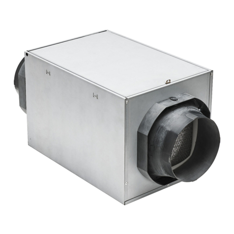
Installation and Maintenance Kitchen Exhaust Fan GLEB
5
Fläkt Woods 9987GB 2016.02.03 Specifications are subject to alteration without notice
MOUNTING INSTRUCTIONS
5. MOUNTING INSTRUCTIONS
5.1 INSTALLATION OF THE FAN
The fan is secured to a base by M8 pin bolts and nuts (4 pcs) in
mounting holes across anti-vibration mountings, included in
delivery (see 3.1 Design, part 5). The base must be level and
stable. The fan must only be mounted to a horizontal plane.
5.2 CHANGING THE OUTLET DIRECTION
The fan has three possible outlet directions (left/right/upwards),
upwards as standard. Outlet direction can be changed by detach-
ing the standing skids (see 3.1 Design, part 3) and placing them
to desired side of fan casing (fixed with M8 bolts). If the fan is
equipped with optional frequency converter, care should be taken
that the frequency converter is always in upright position, even if
the outlet direction is changed.
5.3 OUTDOOR INSTALLATION
When the fan is installed outdoors all seams of outer side of the
fan casing must be carefully sealed with fireproof sealing com-
pound and motor rain cover must also be installed (available as
an accessory).
5.4 FITTING THE ACCESSORIES
Connections to duct system must always be done with flexible
connections (available as an accessory).
Providing necessary grounding for the accessories is within the
constructor’s field of responsibility.
5.5 SAFETY REGULATIONS
If the fan is equipped with optional frequency con-
verter, care should be taken that the frequency con-
verter is always in upright position, even if the outlet
direction is changed.
The fan must always be equipped with a safety
switch. If the fan is delivered without optional safety
switch, the switch must be provided otherwise.
Residual risk due to inappropriate behaviour or
malfunction during operation cannot be completely
excluded. The system planner or constructor must
prevent the emergence of any hazardous situations
through suitable safety measures.
Note that the impeller may rotate due to the air flow
in the duct system, even if the fan is isolated from
mains.
5.6 ELECTRICAL CONNECTIONS
All electrical connections must be wired by authorised person-
nel only. The necessary electrical and safety precautions must be
taken into account. If the motor is operated by a frequency
converter, the connections must be made according to the in-
structions of the frequency converter manufacturer. The motor
must be grounded.
The fan must always be equipped with a safety switch. Electrical
connections shall be made according to the below drawing.
Motor cable shall be of shielded type and fire proofed in case of
GLEB-6, and shielded with GLEB-1. Shield should be grounded
360° at both ends of the cable.
If the VSD will be mounted separately from the fan, the motor
cable should be no longer than 15 meters.
For parameter settings, see frequency converter manual.
For the correct fan and frequency converter combination,
see chapter 3.4 Frequency converters for fans.
Basic circuit arrangement (not the delivery entity) below:
DOL start only for GLEB HT-version.


