Flame Gard L82-1030-CE User manual
CHG Europe B.V. Hazeldonk 6475 • 4836 LH Breda • The Netherlands • Phone +31 76 596 8699 • Fax +31 76 596 3114
www.keilhardware.com • www.componenthardware.com
INS-L82-10x0-CE Rev. 6/2017
CAUTION
INSPECT CONTENTS IMMEDIATELY AND FILE A CLAIM WITH
DELIVERING CARRIER FOR ANY DAMAGE.
SAVE YOUR BOX AND ALL PACKING MATERIALS.
YOU ARE RESPONSIBLE FOR DAMAGE TO YOUR UNIT
IF RETURNED IMPROPERLY PACKED.
MODEL NO. L82-1030-CE
L82-1040-CE
Step 1
TURN OFF ELECTRICITY AT BREAKER OR FUSE BOX.
Step 2
Determine which cutout to use for the xture.
Step 3
Remove lens cover by turning out at head screws.
(Lens cover is retained by 2 cables to limit movement)
Step 4
Determine which knock out to use and install the grommet which
is supplied with xture. Feed supply wires through the grommet
into xture. The grommet should be cut at the position between
the largest circle and the middle one.
Step 5
Install xture, apply RTV (DOW Corning 732 or equiv.) to
perimeter of mounting ange. Fit into cutout, secure from far side
using screws or bolts (not supplied).
Screws or bolts (not supplied): Thread outer diameter 4mm min.,
thread length 20mm min.
Step 6
Remove 2 screws retaining reector plate, remove reector plate.
Step 7
All supply wires should be H05VVF-3G1.0 degree or higher. They
must withstand 90°C. They must be three-core wires. The cross-
sectional area of each core is 1mm2 min. Strip supply wires, and
ground wire ~9.5mm (3/8”). Connect blue supply wire on terminal
block to blue lead wire. Repeat procedure with brown supply wire
connection to brown lead wire. Secure green/yellow ground lead
to xture ground stud.
Step 8
Place Reector Plate back into original position and fasten the
2 screws.
Step 9
Install Lamps, twist to lock.
Step 10
Align lens cover to xture ange. Turn at head screws into
plastic nut retainers. Adjust screw torque to provide even contact
of beveled stainless frame to surface.
CAUTION: DO NOT OVER TORQUE.
MAINTENANCE AND REPAIR:
Only carry out maintenance and repair that is described in these
instructions. In case of malfunctions and damage please contact
an authorized electrician.
Please turn off power supply before maintenance and let the
product cool down.
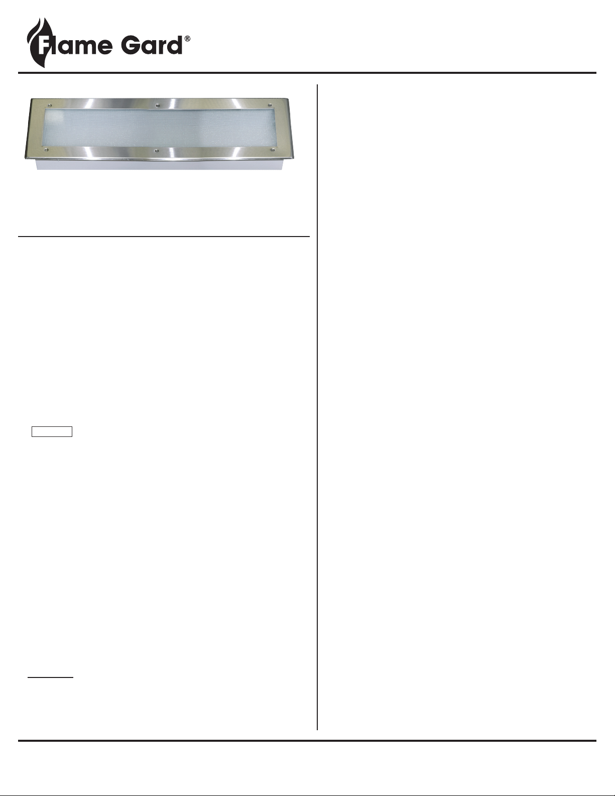
L82 Recessed Canopy Hood Fluorescent Lights
INSTALLATION INSTRUCTIONS
WARNINGS:
• Riskofreorelectricshock.
• Installationtobeperformedbyaqualiedelectricianwith
knowledgeofluminaireelectricalsystems.
• Donotattemptinstallationifnotqualied.
• Allinstallationworkmustcomplywithlocalandnationalelectrical
codes,themanufacturerassumesnoresponsibilityforimproper
installation or application.
• Themountingsurfacemustbestrongenoughtominimizetheriskof
lightxturefallingdown.
• AllSupplyWiresmustbeH05VVF-3G1.0degreeorhigher.Theymust
withstand90°C.
• Electricalsupplytoxturemustbeturnedoffbeforeattemptingto
servicethexture.
• AlwaysmakesurethatthesupplyvoltagematchestheLED
driver voltage.
• CAUTION-RISKOFDAMAGE.UseONLYLEDlightplatespecied
onxture.
•FIXTUREMUSTBEGROUNDED.
•THISDEVICENOTINTENDEDFORUSEWITHEMERGENCYEXITS.
•THISDEVICENOTINTENDEDFORUSEWITHDIMMERS.
• THISDEVICEISFORINDOORUSEONLY
INSTALLATION INSTRUCTIONS:

CHG Europe B.V. Hazeldonk 6475 • 4836 LH Breda • The Netherlands • Phone +31 76 596 8699 • Fax +31 76 596 3114
www.keilhardware.com • www.componenthardware.com
TECHNICAL SPECIFICATION:
This marking indicates that this product should not be disposed
with other household wastes throughout the EU. To prevent
possible harm to the environment or human health from
uncontrolled waste disposal, recycle it responsibly to promote
the sustainable reuse of material resources. To return your
used device, please use the return and collection systems.
Model No. L82-1030-CE L82-1040-CE
Rated Voltage Frequency 220-240V~50/60Hz 220-240V~50/60Hz
Rated Current (A) 0.60 0.72
Power (W) 60 72
IP Rating
66 for the Lens Cover 66 for the Lens Cover
30 for the Outer Casing 30 for the Outer Casing
INSTALLATION DIMENSIONS:
DISPOSAL:
L82 Recessed Canopy Hood Fluorescent Lights
INSTALLATION INSTRUCTIONS
This manual suits for next models
1
Table of contents


