Flame CURVES User manual

“CURVES”
ANALOG RESONANCE FILTERBANK
MANUAL
Version 2.00
FLAME

Manual FLAME Curves Version 2.00
Contents
1. Short description................................................................ 3
2. Hardware / connections...................................................... 4
2.1 Connection to the modular system (Doepfer bus) 4
2.2 Module overview 5
2.3 MIDI connections 6
2.4 AUDIO schemes 7
3. Filterbank ........................................................................... 8
3.1 Structure of the filter bank 8
3.2 Structure of the filter channel 9
3.3 Filter bank control 10
3.4 MODE Sequence 11
- Knob ENVELOPE 12
- Knob VARIATION 13
- Knob FILL 13
3.5 MODE Manually 14
- FILTERTYPE 14
- CUTOFF 15
- SMOOTH 15
4. MIDI functions ................................................................ 16
4.1 Overview 16
4.2 Sync per MIDI 16
4.3 Play filter channels with note commands 16
4.4 Program Change 16
4.5 Control Change (Parameter control) 17
5. Firmware update ................................................................ 18
6. Appendix and technical informations .............................. 19
6.1 Technical details
6.2 Warrenty
6.3 Terms of production
6.4 Disposal
6.5 Support
6.6 Acknowledgment
2

1. Short description
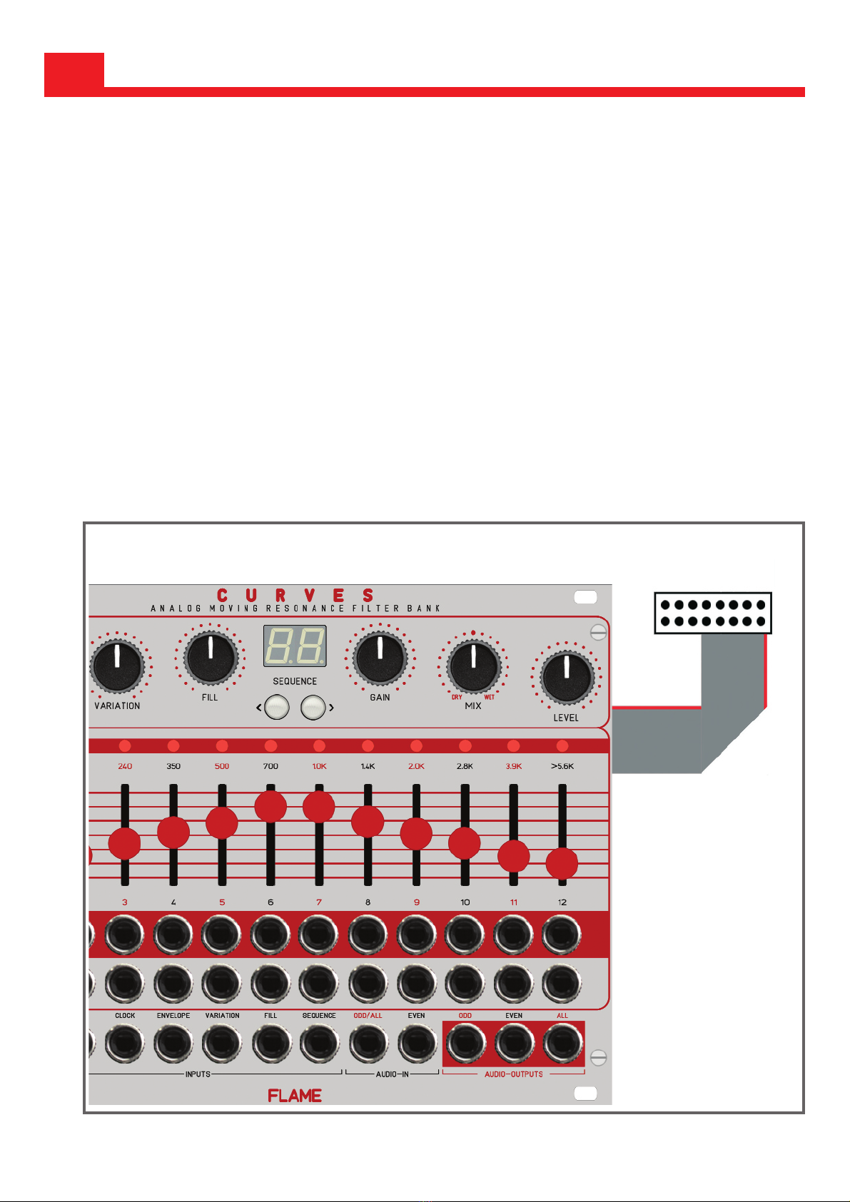
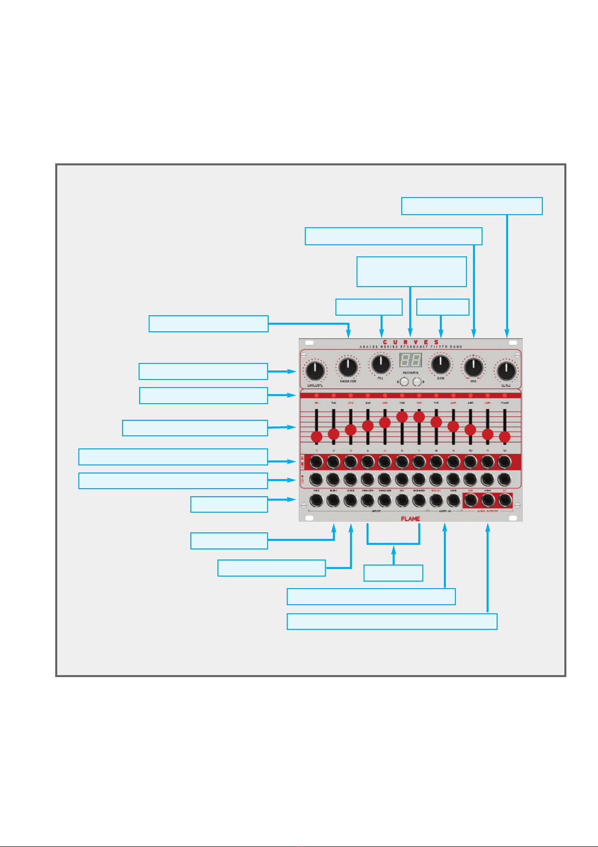
The "Curves" Euro Rack Module is an analogue 12-channel filter bank with 24dB filters and an
integrated modulation sequencer (external clock only) with a wide range of control options. The
controllers of the sequencer can be used to influence the pattern but also to control the filter
channels manually (or via CV).
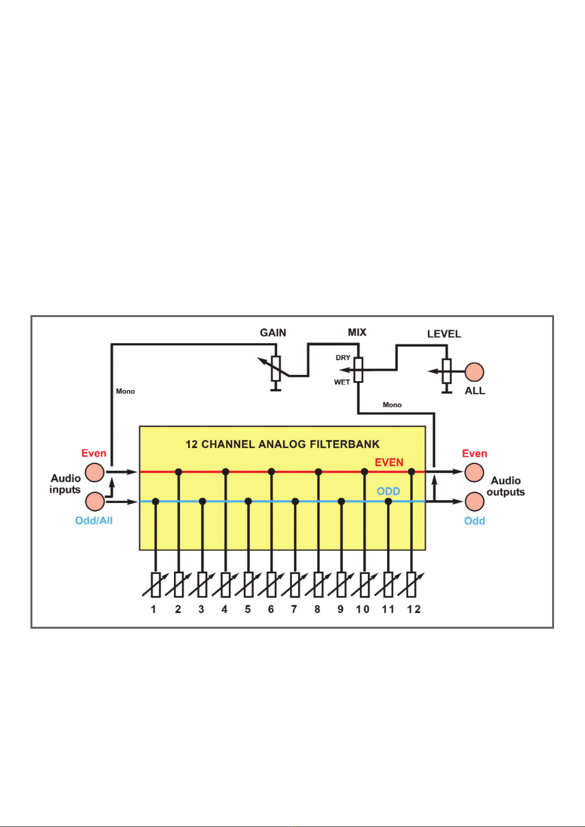
The filter channels are each divided into two channels (odd/even) and can be operated sepa-
rately in stereo or together in mono. There are two inputs for odd(mono)/even, as well as two
individual outputs for odd/even and a mono sum channel including dry-wet mix control and
level control.
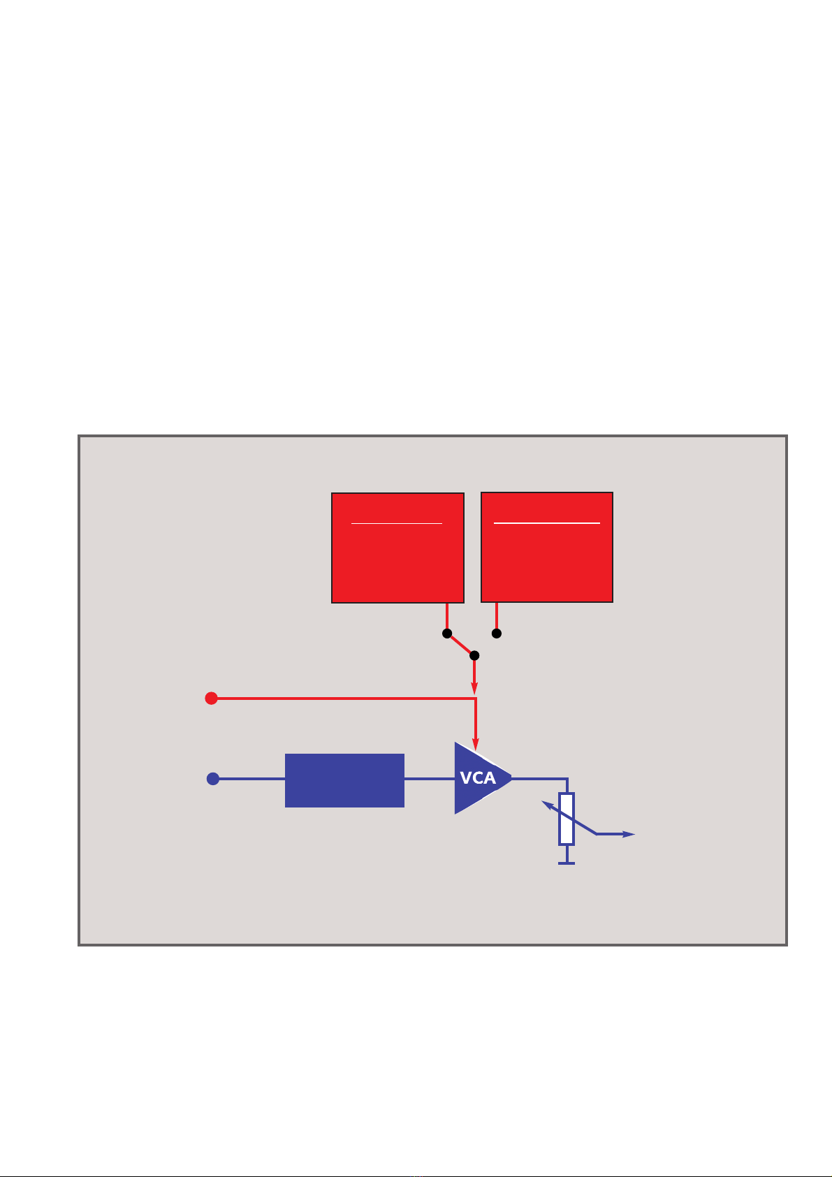
Each of the 12 filter channels also has a separate VCA input (0..+5v) and a separate individu-
al audio output. The filter channels can also be played separately with velocity using MIDI
notes.
The modulation sequencer offers a variety of options. It can be synchronized with an external
clock (16th note) either via MIDI clock or analog via trigger and reset inputs.
There are 99 memory locations available, into which a maximum of 99 four-bar patterns can
be loaded. The patterns are selected either directly by button, by MIDI program change or by
CV input “SEQUENCE”.
With the help of the Curves Editor (PC or MAC version) the patterns can be edited and loaded
into the module. The sequencer is a midi sequencer in tick resolution with settings for gate
time, velocity, track last step and shuffle.
All MIDI settings are made with the editor (e.g. receive MIDI channel and note numbers for the
filter channels).
On the module itself there are 3 controls for influencing the pattern:
- Envelope (different envelopes in trigger or gate mode)
- Variations (random values of velocity and envelope lengths)
- Fill (turn up all filter channels)
All three functions can also be controlled by an external CV via CV inputs.
In manual mode (Sequencer=OFF), these three controls can be used to control the filter chan-
nels directly (and also via CV):
- Envelope (selection of hard detented and soft cutoff movement)
- Variations (choice of filter type: Allpass, Lowpass, Bandpass 1-3, Highpass)
- Fill (cutoff = movement/passing through the bands)
Future firmware updates can simply be loaded using a sysex dump.
AMIDI adapter cable is included.
3

2. Hardware / connections
4
2.1 Connection to the euro rack modular system (Doepfer bus)
The module is delivered with a connected ribbon cable for the Doepfer bus. The red lead marks
-12 volt. Connecting the module please note the right polarity!
If the module is poled accidentally wrong safety diodes avoid the immediate destruction of the
module but further damages cannot be excepted.
So please pay attention: Check the connection various times before switching on!
The current consumption of the module is on average +250mA and -170mA.
CAUTION!
Do not accidentally connect the MIDI THRU output to high CV voltages! This can possibly dama-
ge the hardware!
-12V
Ground
Ground
Ground
+12V

5
2.2 Modul overview
Fill / Cutoff
Random / Filtertype
Envelope / Smooth
Filter channel LEDs
Sliders channel volume
Filter channel direct audio outputs
MIDI input
CV inputs
Reset input
16th clock input
Audio inputs: odd/mono, even
Audio outputs: odd, even, ALL (mono)
Filter channel single VCA inputs
Input gain
Sequence selector
keys + display
Mix Dry-Wet audio output ALL
Level audio output ALL

KEYBOARD/CONTROLLER
Examples of possible connections:
6
COMPUTER
2.3 MIDI connections
The module has a MIDI INPUT socket (3.5mm mini jack in TRS-B standard) for controlling parame-
ters, loading/editing of sequences or firmware updates via sysex. Connect the MIDI input to the MIDI
output of your keyboard/controller or computer. An appropriate commercially available adapter (MIDI-
DIN to Mini TRS-B) or a 3.5mm stereo jack cable is used for the MIDI connection. Acorresponding
adapter is included.
3,5mm (1/8 inch) mini jack
stereo cabel
Adaptor schemata
MIDI DIN jack to
3,5mm (1/8 inch) mini jack
MIDI TRS-B standard

2.4 AUDIO schemes
The module has two audio inputs, which are alternately routed to the filter channels. Input ODD is
routed to the odd-numbered channels and input EVEN to the even-numbered channels. If only one
cable is plugged into the ODD/ALL input socket, the input signal is routed to all filter channels
(ALL=mono input).
EFFECT MIX
Both inputs ODD+EVEN are routed together to the GAIN controller, which is then present as a mono
signal at the MIX controller (dry) (original signal). The MIX controller controls the mixing ratio between
this original signal and the effect signal (wet), which consists of the output sum of all filter channels
(Mono Signa =EVEN + ODD outputs). When the MIX control is in the middle position, the volumes
of the original and effect signals are approximately the same. The LEVEL control then determines the
level of the mix signal at the ALL output socket.
The maximum level of both filter channel groups is always present at the two outputs ODD and
EVEN. This can be viewed as the stereo output of the filter bank. The filter bank is therefore suitable
for stereo applications.
Each of the 12 filter channels has an additional audio output (modular level). The output level is inde-
pendent of the slider position so that the signal can be processed externally even though it has been
removed from the mix.
The sliders only serve as a manual attenuator for the corresponding channel. In order to hear a con-
trolled sequence, the slider must be turned up. The maximum output signal is therefore determined
by the position of the slider.
7

3.1 Structure of the filterbank
The module has an analog filter bank consisting of 12 filter bands. The first 11 filter bands are
24db bandpasses (resonance filters) with fixed frequencies and medium resonance, the excep-
tion being channel 12, a 24dB highpass filter that lets through all higher frequencies from around
5Khz.
The center frequencies of the channels are:
90Hz, 150Hz, 240Hz, 350Hz, 500Hz, 700Hz, 1KHz, 1.4KHz, 2KHz, 2.8KHz, 3.9KHz, >5.6KHz
Each filter band has an output volume slider. This allows you to lower these frequencies in the
overall sound or remove them entirely. Up to this point, the filter bank resembles a graphic equa-
lizer. But the filters in the CURVES have other properties that clearly distinguish them from an
equalizer. On the one hand, there are the resonant filters that particularly amplify the range
around the respective center frequencies. On the other hand, the individual frequency bands do
not overlap. Therefore, the timbre is noticeably affected because it adds resonances at key
points in the sound spectrum.
Each channel has a VCA for electronic volume control through the internal sequencer or sepa-
rately through the BAND CV input. With a CV voltage of 0 to +5v the channel can be regulated
separately. The BAND Leds signal the level of the VCA. Each channel has an additional output
for the audio signal, which can be tapped independently at the socket. The channel control has
no influence on the level (in order to be able to process the signal separately, even though it may
have been removed from the mix).
3. FILTERBANK
8
u
v
w
x
BAND LEDs LED display VCA level of the filter band
BAND SLIDERS Audio filter band attenuators
BAND AUDIO OUT Audio individual outputs of all filter bands
BAND CV IN CV inputs of the VCAs of the filter bands
u
v
w
x

9
3.2 Structure of the filter channel
The filter bank of the module has 12 filter bands.
Each of these filter bands basically consists of a fixed frequency filter (24dB bandpass or high-
pass), a VCA for volume control via CV, and a slider for manually attenuating the audio signal.
The VCAs can be controlled in different ways:
- directly via channel CV input
- Filter simulations by manual controls/CV
- internal modulation sequencer
See the following chapter: “Filter bank control”
FILTER
SEQUENCER
ENVELOPE
GENERATOR
MANUALLY
FILTER
SIMULATION
CV input
CV
Mode
Sequencer
Manually
Audio input
Audio out
Slider

10
u v w
3.3 Filter bank control
x
KNOB ENVELOPE Envelope or smoothing (passing through the filter bands)
KNOB VARIATION Variations (random) or Filtertype (of the filter simulation)
KNOB FILL Turn up the level of all filter bands or cutoff (of the filter simulation)
SELECT MODE/SEQUENCE Pattern or mode selection (oF=filter simulation)
u
v
w
x
The knobs have different functions in the two modes:
MODE SEQUENCE (Display 01..99)
KNOB ENVELOPE Envelopes of the sequence
KNOB VARIATION Random = Envelope/Volume Variations
KNOB FILL level of all filter bands (mix in)
MODE MANUALLY(Display “oF”)
KNOB ENVELOPE Smoothing of passing through the filter bands
KNOB VARIATION Selection of one of 6 filter types
KNOB FILL Adjust filter type cutoff
In CURVES there are two different ways (MODE) to modulate the filter bank:
1. Through an internal modulation sequencer (one track for each filter band) with knobs and CV
controls for envelope, variations (random) and fill mix (additive raising of all filter bands)
2. Manually with the help of a filter type simulation and with controls for cutoff, filter type and
smoothing of the filter bands.
MODE SELECTION
Use the “SEQUENCE” buttons to either select a pattern “01..99” or set the display to “oF” (press
the sequence button “<” until “oF” appears)
01..99 Mode SEQUENCE (Modulation sequencer)
oF Mode MANUALLY(Filter simulations)

To animate the filter bands rhythmically, the CURVES uses a relatively simple sequencer with
12 parallel tracks. The module has 12 envelope generators, one for each filter band, which affect
the output level of the respective filter. The "shape" of the envelope (i.e. the times for attack,
decay or release) depends on the "ENVELOPE" control. This allows differentiated volume cur-
ves to be generated, such as percussive sounds or slowly rising curves.
ACTIVATE SEQUENCE MODE:
Use the buttons to select a sequence between 01 and 99.
The sequencer does not have its own clock and can only be driven externally. This is done eit-
her with MIDI clock (start/stop) or via the CLOCK and RESET sockets. The analog CLOCK input
requires a 16th pulse sequence. Since the sequencer runs internally at a higher resolution, the
clock should run smoothly (the tempo is measured between two clock pulses). The pattern is
reset with the RESET input. If no clock arrives for more than a few seconds, the sequence is
stopped and reset.
The memory contains up to 99 patterns (sequences) with a maximum length of 4 bars. You can
create your own patterns with the CURVES editor and transfer them to the module via MIDI.
More information on this can be found in the editor's help file (see the Download section on the
Flame website).
The following figure shows the editor with a loaded pattern:
3.4 MODE SEQUENCE
11

SEQUENCE MODE KNOBS & CV
The sequence played can be influenced with the three controllers at the top left:
KNOB ENVELOPE
This is one of the most interesting features of the CURVES. When the sequence is played back, the
controller can be used to "morph" through the different forms of the envelope.
When the knob is at ZERO, the sound is short and choppy. The attack and decay phases are very
short. If the control is turned up a little, you can hear the steps decay longer (the decay gets longer).
The envelope is of type AD (Attack-Decay) and is only triggered by the sequencer. The length of the
step (gate time) has no influence on the envelope. However, if the position of the controller is bet-
ween 9 and 12 o'clock, the envelope is set to type AR (Attack-Release). In this area, the gate length
of the step is evaluated and has an influence on the length of the envelope.
The graphic illustrates the behavior of the controller:
12
G
a
t
e
o
n
Trigger Trigger
The function of the controller can also be automatically modulated by a CV. The CV input
“ENVELOPE” is available for this. The input is designed for voltages in the range 0 to +5v.
Effect of the knob on the attack and decay/release times
(0=left stop MAX=right stop)
0MAX
center
Knob position:
Envelope shape:
AD Envelope AD EnvelopeAR Envelope

KNOB VARIATION
With the middle controller "VARIATION" the intensity of random changes in volume and envelope
times can be regulated. This varies a running sequence, and more lively playback patterns or vari-
ations of the sequence result. When the control is set to ZERO, the pattern is played back unchan-
ged.
The following parameters are affected: volume (volume of the step), decay times and release times.
KNOB FILL
The third control “FILL” regulates all VCAs evenly until the maximum volume of all channels is rea-
ched (“filling the channels”). This happens in addition to the playing sequence. The sequence con-
tinues to be heard until the maximum is reached. The effect can be compared to the dry-wet beha-
vior of the MIX controller, where the original signal and the effect signal are mixed. Here, however,
the sequence and the uniform low or high level of all filter bands are mixed.
The graphic below illustrates the effect:
13
Level
filter channel
Original sequence level
Original sequence level + FILL level
Max
1 2 3 4 5 6 7 8 9 10 11 12
Level
filter channel
Original sequence level
Original sequence level + FILL level
Max
1 2 3 4 5 6 7 8 9 10 11 12
Level
filter channel
Original sequence level
Original sequence level + FILL level
Max
1 2 3 4 5 6 7 8 9 10 11 12
FILL
FILL
FILL

When the modulation sequencer is disabled, the filter bank can generate filter simulations. The
individual filter bands are then controlled in such a way that classic filter profiles are generated.
These are controlled with the knobs Envelope, Variation and Fill.
ACTIVATE MANUALLYMODE:
Use the “<” button to set the sequence to “oF”
(possibly press several times!).
In this mode, the controllers have the following functions:
Knob ENVELOPE: SMOOTH = Smoothing of passing through the filter bands
Knob VARIATION: FILTER TYPE = selection of one of 6 filter types
Knob FILL: CUTOFF = Adjust filter type cutoff
FILTERTYPE
The VARIATION control sets one of six filter types. These algorithms use the filter bands to simu-
late classic filter types such as lowpass, bandpass, highpass and other types. This is possible
because each filter band has its own VCA (Voltage Controlled Amplifier) that controls the volu-
me of that band separately. For example, if you slowly increase and decrease the volume of the
channels, starting from the band with the lowest frequency, you get a classic low-pass filter.
The following filter types can be set:
1 - All channels - all bands are turned up simultaneously
2 - Lowpass
3 - Bandpass (1channel)
4 - Bandpass (2 channels)
5 - Bandpass (3 channels)
6 - Highpass
3.5 MODE MANUALLY
14
Pot VARIATION = FILTERTYPE
16
2
34
5

CUTOFF
The FILL control is used to change the filter cutoff frequency. As you turn the knob, the LEDs
indicate the active area of the filter. The filter characteristics can also be seen visually. Only the
filter bands with lit LED are audible.
EXAMPLE OF FILTER MODULATION
Example: Adjusting the lowpass cutoff manually
- Set the CUTOFF (FILL knob) to the middle position
- Set FILTERTYPE to Lowpass (VARIATION knob at 9 o'clock).
- Turn SMOOTH to maximum (ENVELOPE knob fully clockwise)
Now you can use the CUTOFF control (FILL control) to move smoothly through the individual fil-
ter bands like a low-pass filter. You can see this from the glowing LEDs of the filter channels.
The filter type algorithm automatically regulates the volume of the individual filter bands, crea-
ting the effect of a low-pass filter. The other filter types work the same way.
Try them out and listen to the different effects.
SMOOTH
The ENVELOPE knob changes the smoothing of the band sweep with the cutoff control. It can
be softly blended from unsmooth to smooth. With an unsmoothed setting, the bands jump
straight on. With a smooth setting, the bands flow smoothly into one another.
All three functions can also be controlled via the corresponding CV inputs.
15
Knob FILL = CUTOFF
Knob ENVELOPE = SMOOTH
Example: Lowpass

16
4. MIDI FUNCTIONS
The module has extensive MIDI functions. The following MIDI commands can be used:
MIDI-CLOCK Start/Stop: Sequencer clocking
Note Numbers: Triggering the filter bands
Program Change: Selection of a sequence
Control Change: Controlling CURVES parameters
Sysex: Load sequence pattern, firmware update
4.1 Overview
Connect a computer with MIDI interface and sequencer software, or a MIDI device (e.g. drum
machine) that can send MIDI Clock/Start/Stop.
The CURVES sequencer can only run as a slave with MIDI clock. MTC (MIDI Time Code) or
position data (such as Song Position Pointer) is not recognized.
4.2 SYNC per MIDI
Each filter channel can be played with an external keyboard, for example. Anote number is
assigned to each filter band for this purpose. Velocity affects the triggered volume of the filter
band.
Default notes for the filter bands are note numbers 36-47 on MIDI channel 1.
With the CURVES sequence editor, the note numbers and the MIDI channel can be changed.
4.3 Play filter channels with note commands
The module understands program change commands on the set MIDI receive channel (default:
1). The numbers correspond to the sequence numbers, i.e. 1 to 99.
If a program change command is received while the sequencer is running, the pattern is chan-
ged at the next ONE. If the sequencer is stopped, the pattern is switched immediately.
4.4 Program Change (Select sequence pattern)

17
Control change numbers are permanently assigned to all digital functions. The parameters are
controlled with a value between 0 and 127. The controllers are received on the set MIDI recei-
ve channel.
Function Control change number
ENVELOPE_ALL 2
FIL 1
VARIATION 3
VCA_BAND1 4
VCA_BAND2 8
VCA_BAND3 9
VCA_BAND4 10
VCA_BAND5 11
VCA_BAND6 12
VCA_BAND7 13
VCA_BAND8 14
VCA_BAND9 15
VCA_BAND10 16
VCA_BAND1117
VCA_BAND12 18
ENV_BAND1 19
ENV_BAND2 20
ENV_BAND3 21
ENV_BAND4 22
ENV_BAND5 23
ENV_BAND6 24
ENV_BAND7 25
ENV_BAND8 26
ENV_BAND9 27
ENV_BAND10 28
ENV_BAND1129
ENV_BAND12 30
4.5 Parameter control via Control Change
Sequence patterns can be loaded into the module via SYSEX. The CURVES editor can be used
for this. The note numbers and the MIDI receive channel can also be changed with the editor.
4.6 Load sequences via sysex

18
5. FIRMWARE UPDATE
You can easily update the firmware with a MIDI sysex dump. To do so, use a MIDI-sysex-dump-
loader for example the freeware MIDI-OX or Electron C6 (win or mac).
1. Load the firmware sysex file to your computer.
2. Connect the MIDI interface of the computer with the MIDI input of the modul.
Therefore you have to use the provided MIDI adapter accessory.
3. Hold down both sequence keys while you power on the module.
The display shows “UP” (UPDATE).
4. Now send the Sysex firmware file to the module. While the update runs you can see the
progress indicator (display shows counting numbers). The upload during time is
for instance 1,5 minutes.
5. After the update procedure the module reboots automatically
After power on the display shows the current firmware:
U0 (for version 0) or
U1 (for version 1) or
U2 (for version 2) ...
ADVICE:
Sometimes it’s necessary to set the parameter “Delay” or “Timeout” to higher values (such as
80ms) from your used dumploader software.

6. Appendix
6.1. Technical details
Connections:
Ribbon cable adapter for Doepfer bus +/-12Volt
Current consumption: max. +250mA / - 170 mA
Size: Euro rack format 3U / 31HP 157x128,5x40mm
6.2 Warrenty
Beginning from the date of purchase a 2-year warranty is guaranteed for this device in case of
any manufacturing errors or other functional deficiencies during runtime.The warranty does not
apply in case of:
- damage caused by misuse
- mechanical damage arising from careless treatment (dropping, vigorous shaking, mishandling, etc)
- damage caused by liquids penetrating the device
- heat damage caused by overexposure to sunlight or heating
- electric damage caused by improper connecting
(wrong power supply/ jacks/ MIDI connections/ voltage problems).
If you have any complaints please contact your dealer or send an e-mail to:
service@flame-instruments.de
6.3 Terms of production
conformity: CE, RoHS, UL
6.4 Disposal
The device is produced with RoHS-conformity (subject to the regulations of the European Union)
and is free of hazardous substances (like mercury, plumb, cadmium and hexavalent chrome).
But electronical scrap is hazardous waste. Please don't add this to consumer waste. For an
environment friendly disposal of waste please contact your distributor or specialist dealer.
6.3 Support
Updated and additional informations, updates, downloads and more see:
www.flame-instruments.de
6.4 Acknowledgment
For help and assistance big thanks to: Alex4 und Schneiders Büro Berlin, Shawn Cleary
(Analogue haven, Los Angeles), Thomas Wagner, Robert Junge, Anne-Kathrin Metzler, Lena
Bünger, Alex Wolter und Sebastian Preller.
19
Table of contents
Other Flame Recording Equipment manuals