Flammex FMR 3026 User manual
FMF 3545
1
2
1
2
3
9V
9V 9V
9V

3 4
5
< 25 m
> 1 m

4
6 7
> 1 m
5
GBFRITPL DE
Bitte sorgfältig durchlesen und aufbewahren! Mit dem Kauf dieses
Artikels haben Sie sich für ein qualitativ hochwertiges GEV Produkt
entschieden. Bitte lesen Sie diese Bedienungsanleitung sorgfältig durch,
um ein einwandfreies Funktionieren zu gewährleisten. Bewahren Sie
diese Anleitung sorgfältig auf, um gegebenenfalls später nachlesen
zu können. Das Produkt ist nur für den sachgemäßen Gebrauch (wie
in der Bedienungsanleitung beschrieben) bestimmt. Änderungen,
Modifikationen oder Lackierungen dürfen nicht vorgenommen werden,
da sonst jeglicher Gewährleistungsanspruch entfällt.
Produktbeschreibung
Das nachrüstbare Funkmodul sendet und empfängt Alarmsignale in Verbindung
mit dem 9 V Rauchwarnmelder FMR 3026. Sobald der Rauchwarnmelder
Alarm über die Vernetzungsklemme ausgibt, sendet das Funkmodul den
Alarm per Funk an alle umliegenden Funkmodule seiner Funk-Gruppe.
Eine Alarmmeldung wird dabei innerhalb der jeweiligen Funk-Gruppe von
den Funkmodulen in Reichweite einmal weitergeleitet, um auch größere
Übertragungsstrecken überbrücken zu können, wie zum Beispiel vom
Keller über das Erdgeschoss in das Obergeschoss. Wenn der Alarm am
Rauchwarnmelder nicht mehr ansteht, nehmen die Funkmodule nach kurzer
Zeit (bis ca. 1/2 Minute) den Alarm zurück. Es können bis zu 30 Funkmodule
mit Rauchwarnmelder einer Funk-Gruppe zugeordnet werden. Bis zu 8
autarke Funk-Gruppen können programmiert werden, um sich z.B. in
Mehrfamilienhäusern nicht gegenseitig zu stören. Die Funkmodule derselben
Funk-Gruppe dürfen nur innerhalb eines Gebäudes untergebracht sein und
nicht teilweise in Nachbargebäuden installiert werden.
Betrieb/Test
Jeder Melder/Funkmodul, der ein Funksignal direkt vom Verursacher
derselben Funk-Gruppe empfängt, leitet dieses automatisch einmal
weiter. Die Weiterleitung erfolgt erst, wenn der Funkkanal frei ist,
um eine Datenkollision zu vermeiden. Die Weiterleitung quittiert der
jeweils sendende Melder durch 3-4 kurze Töne im Abstand von etwa
5 Sek. Ist der Kanal wieder frei, leitet der nächste Melder/Funkmodul
das Signal weiter und quittiert, usw. Eine verbrauchte Batterie wird
durch den Rauchwarnmelder lokal angezeigt, wie in dessen Anleitung
beschrieben. Das Funkmodul misst die Batterie außerdem selbstständig
ca. alle 20 Min. Die Leerschwelle ist mit ca. 6,9 V so eingestellt, dass
die Meldung erst ausgesendet wird nachdem die Störungsmeldung
vom Rauchwarnmelder selbst angezeigt wird. Die Weiterleitung des
Batterieleersignals quittiert der jeweils sendende Melder durch 3-4 kurze
Töne im Abstand von etwa 5 Sek. Ist der Kanal wieder frei, leitet der nächste
Melder/ Funkmodul das Signal weiter und quittiert, usw.
Hinweis:
Beachten Sie die Anleitung des Rauchwarnmelders.
Programmierung / Inbetriebnahme
Hinweis: Wir empfehlen die Programmierung der Funkmodule
vorzunehmen, bevor Sie die Geräte an der Decke anbringen.
Es dürfen immer nur die 2 Funkmodule zurzeit in Betrieb gesetzt werden,
die gerade programmiert werden sollen und nicht alle gleichzeitig. Ziehen
Sie bei den anderen dazu die 3-polige Klemme des Funkmoduls Abb. 1.3
vom Rauchwarnmelder ab oder klemmen Sie die Batterie ab.
Rauchwarnmelder montiert wird (siehe Anleitung des Rauchwarnmelders).
Die Batterie-Lebensdauer des Rauchwarnmelders wird dadurch verringert.
Der Rauchwarnmelder zeigt einen fälligen Batterietausch an.
richtig angeschlossen, blinkt die rote LED des Rauchwarnmelders ca.
alle 45 Sek. kurz auf.
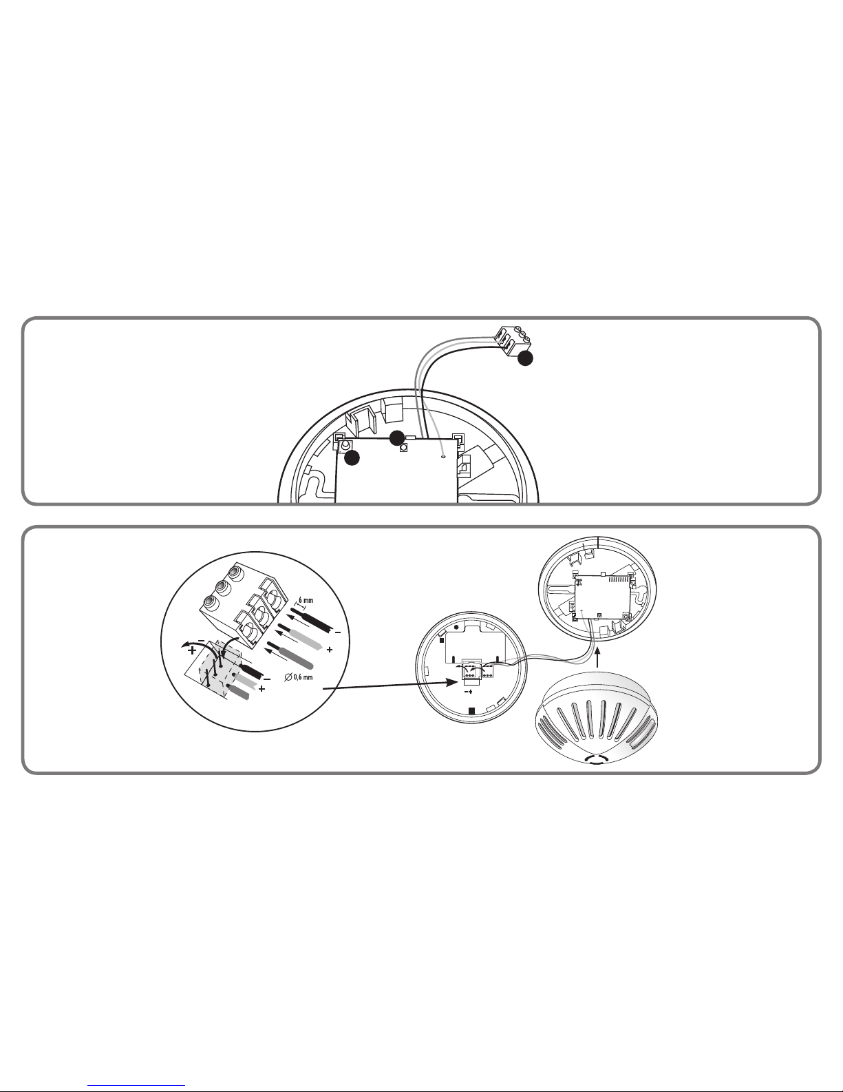
hierzu die grüne Klemme vom Rauchwarnmelder ab (Abb. 2) und stecken
die 3-polige Klemme des Funkmoduls Abb. 1.3 auf den Rauchwarnmelder.
Funk-Vernetzungsmodul FMF 3545

6
Die Klemme muss vorsichtig bis zum Anschlag ganz tief aufgesteckt werden,
bis diese bündig mit den Gehäusestegen des Rauchwarnmelders ist. Das
Funkmodul quittiert den korrekten Anschluss durch kurzes Blinken der roten LED
Abb. 1.1. Der Rauchwarnmelder kann beim Aufstecken einen kurzen Piepton
abgeben. Ist die Klemme falsch herum aufgesteckt, löst der Rauchwarnmelder
sofort Alarm aus. Verrasten Sie den Rauchwarnmelder noch nicht auf dem
Funkmodul, da das Funkmodul erst programmiert werden muss.
Hinweis: Halten Sie einen Mindestabstand von 1 m zwischen den
Funk-modulen ein – auch bei der Montage.
Anlegen einer Funk-Gruppe
Es dürfen immer nur die 2 Funkmodule zurzeit in Betrieb gesetzt werden,
die gerade programmiert werden sollen und nicht alle gleichzeitig.
Halten Sie bei einem Funkmodul die Taste (Abb. 1.2) für ca. 2-3 Sek.
gedrückt. Die rote LED (Abb. 1.1) beginnt dann ca. 1 Mal pro Sek. zu
blinken. Taste wieder loslassen. Das Funkmodul befindet sich für ca.
60 Sek. im Programmiermodus. Betätigen Sie sofort danach bei einem
weiteren Funkmodul die Taste (Abb. 1.2) für ca. 2-3 Sek. Die rote LED
(Abb. 1.1) beginnt dann ca. 1 Mal pro Sek. zu blinken. Taste wieder loslassen.
Das Funkmodul befindet sich für ca. 60 Sek. im Programmiermodus. Beide
Funkmodule programmieren sich dabei gegenseitig automatisch in eine
Funk-Gruppe ein. Der Programmier-Vorgang kann insgesamt bis zu ca.
60 Sek. dauern. War die Programmierung erfolgreich, leuchten an beiden
Funkmodulen die roten LEDs (Abb. 1.1) für 2-3 Sek. permanent. Sollten
nach ca. 60 Sek. die roten LEDs nicht permanent für 2-3 Sek. leuchten,
war der Programmier-Vorgang nicht erfolgreich und die Funkmodule gehen
wieder zurück in den Normalmodus. In diesem Fall muss der Programmier-
Vorgang wiederholt werden. Es können bis zu 30 Funkmodule einer Funk-
Gruppe zugeordnet werden.
Erweitern einer bestehenden Funk-Gruppe
Es dürfen immer nur die 2 Funkmodule zurzeit in Betrieb gesetzt
werden, die gerade programmiert werden sollen und nicht alle
gleichzeitig. Zur Erweiterung einer bestehenden Funk-Gruppe setzen Sie
ein beliebiges Funkmodul aus der zu erweiternden Funk-Gruppe in den
Programmiermodus, indem Sie die Taste (Abb.1.2) für 10 ca. 2-3 Sek.
gedrückt halten. Bei den anderen Funkmodulen darf die 3-polige Klemme des
Funkmoduls Abb. 1.3 nicht auf dem Rauchwarnmelder stecken. Die rote LED
(Abb. 1.1) beginnt dann ca. 1 Mal pro Sek. zu blinken. Taste wieder loslassen.
Das Funkmodul befindet sich für ca. 60 Sek. im Programmiermodus. Betätigen
Sie sofort danach die Taste des Funkmoduls, das hinzugefügt werden soll
für ca. 2-3 Sek. Die rote LED beginnt dann ca. 1 Mal pro Sek. zu blinken.
Taste wieder loslassen. Das Funkmodul befindet sich für ca. 60 Sek. im
Programmiermodus. Das Funkmodul, das hinzugefügt werden soll, wird
dadurch automatisch in die bestehende Funk-Gruppe mit aufgenommen. Der
Programmier-Vorgang kann insgesamt bis zu ca. 60 Sek. dauern.
Anlegen einer zusätzlichen Funk-Gruppe
Es dürfen immer nur die 2 Funkmodule zurzeit in Betrieb gesetzt
werden, die gerade programmiert werden sollen und nicht alle
gleichzeitig. Gehen Sie so vor wie in Anlegen einer Funk-Gruppe
beschrieben. Programmieren Sie lediglich die Funkmodule, die in
die zusätzliche Funk-Gruppe aufgenommen werden sollen. Beziehen
Sie dabei kein Funkmodul einer bereits vorhandenen Funk-Gruppe
mit ein. Bis zu 8 autarke Funk-Gruppen sind möglich.
Hinweis: Die Taste Abb. 1.2 ist nach Betätigung für 5 Min.
gesperrt. Das gilt auch für Funk-Module, die das TestTelegramm
empfangen haben.
Montage
Hinweis: Beachten Sie die Anleitung
des Rauchwarnmelders.
Vermeiden Sie feuchte Umgebungen und extreme Temperaturen (Abb. 3).
Beachten Sie, dass Metallflächen und metallhaltige Wände die Funk-
Signale besonders stark dämpfen oder reflektieren können (Abb. 4).

7
GBFRITPL DE
Halten Sie bei der Montage einen Mindestabstand von 1 m zwischen
den Funkmodulen (Abb. 5). Halten Sie einen Mindestabstand von 1 m zu
großen Geräten (Abb. 6).
Rauchwarnmelders fest. Montieren Sie die Funkmodule an der Decke.
Die Funkreichweite ist am größten in Richtung der Gehäusemarkierung
am Funkmodul Abb. 7.
den Rauchwarnmelder Abb. 2.
zen Sie den Rauchwarnmelder auf das montierte Funkmodul und
drehen Sie ihn vorsichtig im Uhrzeigersinn, bis er einrastet. Die beiden
Gehäusemarkierungen des Funkmoduls und des Rauchwarnmelders
müssen dabei übereinander liegen Abb. 7. Ist keine Batterie in den Rauch-
warnmelder eingelegt, ist das Einrasten auf dem Funkmodul nicht möglich.
Hinweis: Achten Sie darauf, dass die Anschlussadern nicht über
die Platine des Funkmoduls geführt werden, sondern direkt vom
Gehäuserand zum 3-poligen Stecker am Funkmodul.
Funktionstest durch, indem Sie die Testtaste des Rauchwarnmelders
drücken, bis dieser 3 Alarmtöne abgibt. Beachten Sie dabei die Anleitung
des Rauchwarnmelders. Die Funkmodule/Rauchwarnmelder derselben
Funk-Gruppe zeigen den Alarm akustisch an und gehen automatisch nach
kurzer Zeit in den Normalmodus zurück. Leitet ein Melder das AUS-Signal
weiter, quittiert er dies durch 3 kurze Töne. Siehe Kapitel BETRIEB/TEST.
Das Gerät ist zugelassen für den Vertrieb in der Europäischen
Gemeinschaft.
Hiermit erklärt die Firma GEV GmbH, dass sich dieses Gerät
(Funk-Vernetzungsmodul FMF 3545) in Übereinstimmung mit den
grundlegenden Anforderungen und den anderen relevanten Vorschriften
der Richtlinie 1999/5EG befindet. Die komplette Konformitätserklärung
kann abgerufen werden unter: www.gev.de
Recycling-Hinweis :
Dieses Gerät darf nicht mit dem unsortierten Siedlungsabfall
entsorgt werden. Besitzer von Altgeräten sind gesetzlich dazu
verpflichtet, dieses Gerät fachgerecht zu entsorgen. Informationen
erhalten Sie von Ihrer Stadt- bzw. Gemeindeverwaltung.
Technische Daten :
Produkt FMF 3545
Frequenz 868 MHz
Betriebsspannung 9 V aus dem Rauchwarnmelder
Temperaturbereich 0° C bis +40° C
Relative Luftfeuchtigkeit 0 - 90 % nicht kondensierend
Abmessungen Ø 106 mm, H 12 mm
Farbe weiß
Technische und optische Änderungen ohne Ankündigung vorbehalten.
GEV GmbH
Heidenhofweg 16
25499 Tangstedt
Germany
Fax: +49 (0)180/59 58 555
www.gev.de

8
Please read carefully and retain! In buying this item you have opted for a
high-quality GEV product. Please read these user instructions carefully
to ensure the device is used correctly. Keep them in a safe place for
future reference. Use this product only as intended (as set out in the user
instructions). Any changes or modifications to the product or painting it
will result in loss of warranty.
Product description
The retrofittable radio module sends and receives alarm signals in conjunction
with the smoke detector FMR 3026. As soon as the smoke detector emits an
alarm via the network terminal, the radio module sends the alarm via radio to
all radio modules in its radio group. This process involves the radio modules
that are in range forwarding an alarm message within the respective radio
group once. This alarm message even bypasses transmission paths that are
particularly long, such as from the basement to the top floor via the ground
floor, for example. When the alarm is no longer active at the smoke detector,
the radio modules cancel the alarm after a short time (up to approximately 30
seconds). Up to 30 radio modules with smoke detectors can be assigned to a
radio group. Up to eight independent radio groups can be programmed so that
modules do not interfere with each other within blocks of flats, for example.
The radio modules assigned to the same radio group must only be located
within one building. It is not permitted to install some of the radio modules
in neighbouring buildings.
Operation/testing
Each detector/radio module that receives a radio signal directly from the signal
origin in the same radio group forwards this signal forwards once automatically.
To avoid data collision, the signal is forwarded only when the radio channel
is free. Each detector sending a signal acknowledges that the signal has
been forwarded by emitting 3–4 short sounds at intervals of approximately
five seconds. When the channel is free again, the next detector/radio module
forwards the signal and acknowledges it, and so on. When a battery is
drained, this is displayed locally on the smoke detector, as described in the
instructions for the smoke detector. In addition, the radio module automatically
measures the battery approximately every 20 minutes. The drained threshold
value is set to approximately 6.9 V, so that the message will be sent only after
the fault message is displayed by the smoke detector itself. Each detector
sending a battery signal acknowledges that the signal has been forwarded by
emitting 3–4 short sounds at intervals of approximately five seconds. When
the channel is free again, the next detector/radio module forwards the signal
and acknowledges it, and so on.
Note: Follow the instructions for the smoke detector.
Programming/commissioning
Note: We recommend programming the radio modules before installing
the equipment on the ceiling.
At any one time, activate only the two radio modules that are to be programmed
and not every module simultaneously. To ensure that the other radio modules
remain deactivated, remove the three-pin terminal of the radio module (Fig. 1.3)
from the smoke detector or disconnect the battery for all other modules.
is housed inside the smoke detector (see the instructions for the smoke
detector). Sharing the battery means that the battery life of the smoke
detector is reduced. The smoke detector indicates when it is time to change
the battery.
smoke detector flashes briefly approximately every 45 seconds to indicate
that the battery is fitted correctly.
terminal from the smoke detector (Fig. 2) and plug the three-pin terminal of
the radio module (Fig. 1.3) onto the smoke detector. Carefully plug in the
terminal fully by inserting it as far as it will go until it is flush with the housing
of the smoke detector. The radio module acknowledges that the terminal
has been connected correctly with a short flash of the red LED (Fig. 1.1).
Radio network module FMF 3545
9
GBFRITPL DE
The smoke detector may emit a short beeping sound when the terminal is
being plugged in. If the terminal is attached incorrectly, the smoke detector
triggers an alarm immediately. Do not yet engage the smoke detector on
the radio module, as the radio module must be programmed first.
Note: Maintain a minimum distance of one metre between the
radio modules, even during installation.
Creating a radio group
At any one time, activate only the two radio modules that are to be
programmed and not every module simultaneously. Hold down the
button (Fig. 1.2) on a radio module for approximately 2–3 seconds. The
red LED (Fig. 1.1) then begins to flash approximately once every second.
Release the button again. The radio module enters programming mode for
approximately 60 seconds. After this period, immediately press the button
(Fig. 1.2) on another radio module for approximately 2–3 seconds. The
red LED (Fig. 1.1) then begins to flash approximately once every second.
Release the button again. The radio module enters programming mode
for approximately 60 seconds. During this time, both radio modules
reciprocally program themselves into a radio group automatically. The
programming process can take up to approximately 60 seconds in total.
If programming was successful, the red LEDs (Fig. 1.1) on both radio
modules light up permanently for 2–3 seconds. If after approximately 60
seconds the red LEDs do not light up permanently for 2–3 seconds, the
programming process was not successful and the radios modules return
to normal mode. In this event, the programming process must be repeated.
Up to 30 radio modules can be assigned to a radio group.
Expanding an existing radio group
At any one time, activate only the two radio modules that are to be
programmed and not every module simultaneously. To expand an
existing radio group, switch any radio module from the radio group to
be expanded to the programming mode by holding down the button
(Fig 1.2) for approximately 2–3 seconds. For the other radio modules,
do not plug the three-pin terminals of the radio modules (Fig. 1.3)
onto the smoke detector. The red LED (Fig. 1.1) then begins to flash
approximately once every second. Release the button again. The radio
module enters programming mode for approximately 60 seconds.
After this period, immediately press the button of the radio module to
be added for approximately 2–3 seconds. The red LED then begins to
flash approximately once every second. Release the button again. The
radio module enters programming mode for approximately 60 seconds.
During this time, the radio module to be added will be automatically
incorporated into the existing radio group. The programming process
can take up to approximately 60 seconds in total.
Creating an additional radio group
At any one time, activate only the two radio modules that are to be
programmed and not every module simultaneously. Proceed in the same
manner as described in the section entitled „Creating a radio group“.
Program only the radio modules to be incorporated into the additional
radio group. During this process, do not integrate a radio module that is
already assigned to another radio group. It is possible to create up to eight
independent radio groups.
Note: The button (Fig. 1.2) is locked for five minutes after being
activating. This also applies for the radio modules that have received
the test radio message.
Installation
Note: Follow the instructions for the smoke detector.
Avoid damp environments and extreme temperatures (Fig. 3).
Note that metal surfaces and walls containing metal can severely dampen
or reflect the radio signals (Fig. 4). Maintain a minimum distance of one
metre between the radio modules (Fig. 5) during installation. Maintain a
minimum distance of one metre from large appliances (Fig. 6).
10
installation location. Install the radio modules on the ceiling. The radio
range is greatest in the direction of the marking on the housing of the radio
module (Fig. 7).
of the smoke detector (Fig. 2).
turn the smoke detector in a clockwise direction until it locks into place.
During this process, the marking on the housing of the radio module
and the marking on the housing of the smoke detector must align
with each another (Fig. 7). If a battery is not inserted into the smoke
detector, it is not possible to lock the smoke detector in place on the
radio module.
Note: Make sure that the connection wires are not routed over
the circuit board of the radio module — instead, they must be
routed directly from the edge of the housing to the three-pin plug
on the radio module
function test by pressing the test button on the smoke detector until
the smoke detector emits three alarm sounds. When performing the
function test, follow the instructions for the smoke detector. The radio
modules/smoke detectors of the same radio group signal the alarm
acoustically and automatically return to normal mode after a short
period of time. If a detector forwards the OUT signal, it acknowledges
that it has done so by emitting three short sounds. See the section
entitled „Operation/testing“.
The device is approved for operation inside the European Community.
GEV GmbH hereby declares that this device (Radio Transmit and Receive
Module FMF 3545) accords with the fundamental requirements and the
other relevant regulations of guideline 1999/5EG. The full declaration of
conformity can be seen under: www.gev.de
Recycling guidelines:
This device must not be disposed of as unsorted household waste.
Used devices must be disposed of correctly. Contact your local town
council for more information.
Technical data:
Type designation FMF 3545
Frequency 0–868 MHz
Operating voltage 9V from the smoke detector
Working temperature range 0–40°C
Relative humidity 0–90% non-condensing
Dimensions Ø 106 mm, height 12 mm
Colour white
Technical and design features may be subject to change.
GEV GmbH
Heidenhofweg 16
25499 Tangstedt
Germany
Fax: +49 (0)180/59 58 555
www.gev.de
11
GBFRITPL DE
Veuillez lire cette notice avec une grande attention et la conserver !
En achetant cet article, vous avez choisi un Produit GEV de haute
qualité. Pour l’utiliser dans les meilleures conditions, veuillez lire
attentivement ce mode d’emploi. Conservez soigneusement ce dernier
en vue d’une consultation future. Ce produit ne doit être utilisé
que dans les conditions prévues par le présent mode d’emploi.
Toute modification (physique, esthétique, etc.) du produit entraîne
l’annulation de la garantie.
Description du produit
Ce module radio peut être intégré à des installations existantes : associé
aux détecteurs de fumée 9 V FMR 3026. Dès que le détecteur de fumée
émet un signal d‘alarme via la borne réseau, le module l‘envoie à tous les
modules radio de son groupe situés à proximité. Le signal d‘alarme est
donc retransmis une fois au sein du groupe par les modules radio à portée,
afin de pouvoir couvrir également les longues distances de transmission.
Le signal est par exemple envoyé de la cave au rez-de-chaussée, puis du
rez-de-chaussée au premier étage. Lorsque le détecteur de fumée arrête
d‘émettre l‘alarme, les modules radio interrompent à leur tour l‘émission
au bout d‘environ 30 secondes. Jusqu‘à 30 modules radio peuvent être
aectés à un même groupe radio. Jusqu‘à 8 groupes radio indépendants
peuvent être programmés pour éviter notamment que les dispositifs des
diérents foyers d‘un même immeuble collectif ne s‘actionnent entre eux.
Les modules d‘un même groupe radio doivent impérativement être installés
au sein du même bâtiment.
Fonctionnement/Test
Tous les détecteurs/modules radio, qui reçoivent le signal radio directement
de l‘appareil à l‘origine de l‘alarme appartenant au même groupe,
retransmettent une fois ce signal de manière automatique. La transmission
se produit uniquement lorsque le canal radio est libre afin d‘éviter un
éventuel conflit de données. L‘appareil émetteur confirme la transmission
en produisant 3 ou 4 sons brefs espacés d‘environ 5 secondes. Lorsque le
canal est de nouveau libre, la transmission continue d‘appareil en appareil
sur le même modèle. Si la pile d‘un détecteur de fumée est déchargée, ce
détecteur indique lui-même cette information, comme décrit dans ce mode
d‘emploi. Le module radio mesure également la charge de la pile environ
toutes les 20 minutes de façon autonome. Le seuil de déchargement est
réglé sur 6,9 V. Ainsi, le signal est envoyé après l‘indication du défaut par
le détecteur de fumée concerné. La transmission du signal de niveau de
chargement faible est indiquée par chaque appareil émetteur par le biais
de 3 ou 4 sons brefs espacés d‘environ 5 secondes. Lorsque le canal
est de nouveau libre, la transmission continue d‘appareil en appareil sur
le même modèle.
Remarque : reportez-vous également au mode d‘emploi du
détecteur de fumée.
Programmation/Mise en service
Remarque : Nous vous recommandons de programmer la radio
modules avant d‘installer le matériel sur le plafond.
Mettez sous tension uniquement les deux modules radio sur le point
d‘être programmés. Retirez la borne tripolaire du module radio des autres
détecteurs (fig. 1.3) ou débranchez leur pile.
dans le détecteur (cf. mode d‘emploi du détecteur). La durée de vie de la
pile du détecteur est donc réduite. Le détecteur de fumée indique lorsque
la pile doit être remplacée.
les 45 secondes si le raccordement est correctement eectué.
du détecteur (fig. 2) et placez la borne tripolaire du module radio (fig. 1.3)
sur le détecteur. Installez la borne avec précaution en l‘enfonçant jusqu‘à
la butée. Elle doit s‘aligner parfaitement avec les nervures du boîtier. Le
module radio confirme le raccordement par un clignotement bref de la
LED rouge (fig. 1.1).
Module radio de mise en réseau FMF 3545
12
Le détecteur de fumée peut émettre un bref bip sonore lors de l‘installation. Si la
borne n‘est pas correctement installée, le détecteur déclenche immédiatement
l‘alarme. N‘enclenchez pas encore le détecteur sur le module radio. Vous devez
d‘abord programmer le module.
Remarque : maintenez une distance minimale de 1 m entre les
modules radio, même pendant le montage.
Création d‘un groupe radio
Mettez sous tension uniquement les deux modules radio sur le point d‘être
programmés. Maintenez la touche du module radio (fig. 1.2) enfoncée
pendant 2 à 3 secondes. La LED rouge (fig. 1.1) se met alors à clignoter
environ 1 fois par seconde. Relâchez la touche. Le module radio se
trouve en mode programmation pour une durée de 60 secondes environ.
Actionnez immédiatement la touche d‘un autre module radio (fig. 1.2)
pendant 2 à 3 secondes. La LED rouge (fig. 1.1) se met alors à clignoter
environ 1 fois par seconde. Relâchez la touche. Le module radio se trouve
en mode programmation pour une durée de 60 secondes environ. Les
deux appareils se paramètrent automatiquement pour former ensemble
un groupe radio. Le processus de programmation peut durer jusqu‘à 60
secondes environ. Si la programmation a été eectuée avec succès, les
LED rouges (fig. 1.1) des deux appareils restent allumées pendant 2 à 3
secondes. Si après 60 secondes, les LED rouges ne restent pas allumées
pendant 2 à 3 secondes, le processus de programmation a échoué et les
modules radio sont repassés en mode normal. Dans ce cas, recommencez
la programmation. Jusqu‘à 30 modules radio peuvent être aectés à un
même groupe radio.
Ajout d‘un module radio à un groupe radio existant
Mettez sous tension uniquement les deux modules radio sur le point d‘être
programmés. Pour ajouter un module radio à un groupe radio existant,
mettez l‘un des modules radio appartenant au groupe radio en mode
programmation en maintenant sa touche (fig. 1.2) enfoncée pendant 2
à 3 secondes. La borne tripolaire du module radio (fig. 1.3) des autres
détecteurs de fumée ne doit pas se trouver sur le détecteur. La LED rouge
(fig. 1.1) se met alors à clignoter environ 1 fois par seconde. Relâchez la
touche. Le module radio se trouve en mode programmation pour une
durée de 60 secondes environ. Actionnez immédiatement la touche du
module radio à ajouter pendant 2 à 3 secondes. La LED rouge se met alors
à clignoter environ 1 fois par seconde. Relâchez la touche. Le module
radio se trouve en mode programmation pour une durée de 60 secondes
environ. L‘appareil que vous souhaitez ajouter est ainsi automatiquement
intégré au groupe radio existant. Le processus de programmation peut
durer jusqu‘à 60 secondes environ.
Création d‘un groupe radio supplémentaire
Mettez sous tension uniquement les deux modules radio sur le point
d‘être programmés. Procédez comme indiqué dans la partie Création
d‘un groupe radio. Programmez uniquement les modules radio qui
doivent être intégrés au groupe radio supplémentaire. N‘intégrez en
aucun cas un module radio appartenant déjà à un groupe radio existant.
Vous pouvez créer jusqu‘à 8 groupes radio indépendants.
Remarque : la touche (fig. 1.2) est verrouillée pendant 5 minutes
après actionnement. Cette remarque concerne également les
modules radio ayant reçu le message test.
Montage
Remarque : reportez-vous également au mode d‘emploi du
détecteur de fumée
Évitez toute exposition à l‘humidité et aux températures très élevées (fig. 3).
Les surfaces métalliques et les cloisons contenant du métal peuvent aaiblir
ou réfléchir les signaux radio de manière considérable (fig. 4). Maintenez
une distance minimale de 1 m entre les modules radio lors de l‘installation
(fig. 5). Maintenez une distance minimale de 1 m avec les appareils de
grandes dimensions (fig. 6).
13
GBFRITPL DE
de fumée. Installez le module radio auplafond. Laportéeradioélectrique
est à son maximum en direction du repère du boîtier du module
radio (fig. 7).
détecteur de fumée (fig. 2).
le avec précaution dans le sens des aiguilles d‘une montre jusqu‘à
enclenchement. Les repères des boîtiers du module radio et du
détecteur doivent être superposés (fig. 7). Si la pile du détecteur n‘est
pas insérée, l‘enclenchement sur le module radio est impossible.
Remarque : les fils de raccordement ne doivent pas passer par
la platine du module radio. Ils doivent être guidés directement
du bord du boîtier à la fiche tripolaire du module radio.
procédez à un test de fonctionnement. Appuyez sur la touche de
test du détecteur de fumée jusqu‘à ce qu‘il émette trois signaux
sonores. Reportez-vous également au mode d‘emploi du détecteur.
Les modules radio/détecteurs de fumée du même groupe émettent
également un signal d‘alarme, puis retournent automatiquement en
mode normal après quelques instants. Si un détecteur transmet un
signal de sortie, il émet trois sons brefs pour le confirmer. Cf. chapitre
Fonctionnement/Test.
L’appareil est autorisé à la vente dans les pays de la Communauté
Européenne.
Par la présente, la Firme GEV GmbH déclare que le présent appareil
(module émetteur-récepteur radio FMF 3545) est conforme aux exigences
de base et autres prescriptions applicables de la Directive 1999/5/
CE. La déclaration de conformité complète peut être obtenue sous les
coordonnées suivantes : www.gev.de
Recyclage : Cet appareil ne doit en aucun cas être jeté avec les
déchets ménagers. Les propriétaires d‘équipements électriques ou
électroniques usagés ont en eet l‘obligation légale de les déposer
dans un centre de collecte sélective. Informez-vous sur les possibilités
de recyclage auprès de votre municipalité.
Caractéristiques techniques :
Produit – FMF 3545
Fréquence – 868 MHz
Tension d’alimentation – 9V provenant du détecteur de fumée
Température de fonctionnement – 0 à 40 °C
Taux d‘humidité relative – 0 à 90 %, sans condensation
Dimensions – Ø 106 mm, hauteur 12 mm
Couleur – blanc
Sous réserve de modifications techniques et esthétiques.
GEV GmbH
Heidenhofweg 16
25499 Tangstedt
Germany
Fax: +49 (0)180/59 58 555
www.gev.de
14
Leggere attentamente e conservare!
Con l’acquisto di questo articolo si è scelto un prodotto GEV di qualità
superiore. Leggere attentamente le istruzioni per l’uso per garantire
un corretto funzionamento e conservarle con cura per una eventuale
consultazione successiva. Il prodotto è destinato solo all’utilizzo previsto
(come descritto nelle istruzioni per l’uso). Non è consentito eseguire
variazioni, modifiche o verniciature, pena l’annullamento della garanzia.
Descrizione del prodotto
Questo modulo radio aggiornabile invia e riceve segnali di allarme se collegato
con i rivelatori di fumo da 9 V FMR 3026. Non appena il rivelatore di fumo
emette un segnale di allarme tramite il terminale di rete, il modulo radio invia
l‘allarme a tutti i moduli radio circostanti del proprio gruppo. In questo caso i
moduli radio a portata inoltrano per una volta un messaggio di allarme all‘interno
del rispettivo gruppo radio al fine di poter coprire anche maggiori distanze
di trasmissione, come ad esempio il percorso dalla cantina al primo piano
passando per il pianoterra. Se il rivelatore di fumo non emette più l‘allarme,
i moduli radio ritirano l‘allarme dopo un breve tempo (circa 1/2 minuto). È
possibile assegnare fino a 30 moduli radio con rivelatore di fumo a un gruppo
radio. È possibile programmare fino a 8 gruppi radio indipendenti che non
interferiscono reciprocamente ad es. in un condominio. I moduli radio di uno
stesso gruppo radio si possono installare solo all‘interno di un edificio e non
possono essere distribuiti parzialmente in edifici adiacenti.
Esercizio/test
Ogni rivelatore/modulo radio che riceve un segnale radio direttamente
dalla fonte dello stesso gruppo radio lo inoltra automaticamente. L‘inoltro
avviene solo se il canale radio è libero, al fine di evitare collisioni di dati. Il
rivelatore che emette il segnale ne conferma l‘inoltro mediante 3-4 brevi
segnali a una distanza di circa 5 secondi. Quando il canale è di nuovo libero,
il rivelatore/modulo radio successivo inoltra il segnale e lo conferma, ecc.
Una batteria esaurita viene segnalata dal rivelatore di fumo a livello locale,
come descritto nelle rispettive istruzioni. Il modulo radio esegue inoltre
una misurazione autonoma della batteria circa ogni 20 minuti. Il livello di
batteria esaurita è impostato a circa 6,9 V in modo tale che il messaggio
venga visualizzato dallo stesso rivelatore di fumo solo dopo il messaggio
di errore. Il rivelatore che emette il segnale di batteria esaurita ne conferma
l‘inoltro mediante 3-4 brevi toni a una distanza di circa 5 secondi. Quando
il canale è di nuovo libero, il rivelatore/modulo radio successivo inoltra il
segnale e lo conferma, ecc.
Nota : Rispettare le istruzioni del rivelatore di fumo.
Programmazione/messa in funzione
Nota : Si consiglia di programmare la radio moduli prima di installare
l‘apparecchio sul sotto.
Si possono mettere in funzione contemporaneamente sempre e solo 2
moduli radio da programmare e non tutti insieme. A tale scopo staccare
dal rivelatore di fumo il morsetto tripolare del modulo radio (fig. 1.3) oppure
scollegare la batteria.
installata nel rivelatore di fumo (v. istruzioni del rivelatore di fumo). Questo
riduce la durata della batteria del rivelatore di fumo. Il rivelatore di fumo
indica la necessità di un‘imminente sostituzione della batteria.
collegata correttamente, il LED rosso del rivelatore di fumo lampeggia
brevemente per circa 45 secondi.
il morsetto verde dal rivelatore di fumo (fig. 2) e inserire il morsetto tripolare
del modulo radio (fig. 1.3) nel rivelatore di fumo. Il morsetto deve essere
inserito con cautela fino a fine corsa, fino a quando viene a trovarsi
allineato con i profili dell‘involucro del rivelatore di fumo. Il modulo radio
conferma il corretto collegamento mediante un breve lampeggiare del LED
rosso (fig. 1.1). Nel momento dell‘inserimento il rivelatore di fumo potrebbe
emettere un breve bip. Se il morsetto non è collegato correttamente,
Modulo radio di rete FMF 3545
15
GBFRITPL DE
il rivelatore di allarme emette subito un allarme. Non incastrare ancora
il rivelatore di fumo sul modulo radio in quanto quest‘ultimo deve
ancora venire programmato.
Nota: Mantenere una distanza minima di 1 m tra i moduli radio,
anche durante il montaggio.
Creazione di un gruppo radio
Si possono mettere in funzione contemporaneamente sempre e solo
2 moduli radio da programmare e non tutti insieme. Nel modulo radio
tenere il tasto (fig. 1.2) premuto per circa 2-3 secondi. Il LED rosso
(fig. 1.1) inizia a lampeggiare circa 1 volta al secondo. Rilasciare il
tasto. Il modulo radio si imposta per circa 60 secondi in modalità di
programmazione. Subito dopo azionare il tasto (fig. 1.2) di un altro
modulo radio per circa 2-3 secondi. Il LED rosso (fig. 1.1) inizia a
lampeggiare per circa 1 volta al secondo. Rilasciare il tasto. Il modulo
radio si imposta per circa 60 secondi in modalità di programmazione.
Entrambi i moduli radio si programmano reciprocamente in modo
automatico in un gruppo radio. La procedura di programmazione può
durare complessivamente fino a circa 60 secondi. Se la programmazione
ha avuto esito positivo, i LED rossi (fig. 1.1) su entrambi i moduli radio
lampeggiano in modo permanente per circa 2-3 secondi. Se dopo circa
60 secondi i LED rossi non dovessero illuminarsi per circa 2-3 secondi
in modo permanente, la procedura di programmazione non ha avuto
esito positivo e i moduli radio tornano nuovamente in modalità normale.
In questo caso è necessario ripetere la procedura di programmazione.
È possibile attribuire fino a 30 moduli radio un gruppo radio.
Ampliamento di un gruppo radio esistente
Si possono mettere in funzione contemporaneamente sempre e solo
2 moduli radio da programmare e non tutti insieme. Per ampliare un
gruppo radio esistente, impostare nella modalità di programmazione
un qualsiasi modulo radio del gruppo radio da ampliare tenendo
premuto il tasto (fig. 1.2) per circa 2-3 secondi. Negli altri moduli radio
il morsetto tripolare del modulo radio (fig. 1.3) non deve essere inserito
nel rivelatore di fumo. Il LED rosso (fig. 1.1) inizia a lampeggiare circa
1 volta al secondo. Rilasciare il tasto. Il modulo radio si imposta per
circa 60 secondi in modalità di programmazione. Subito dopo azionare
il tasto del modulo radio da aggiungere per circa 2-3 secondi. Il LED
rosso inizia poi a lampeggiare circa 1 volta al secondo. Rilasciare
il tasto. Il modulo radio si imposta per circa 60 secondi in modalità
di programmazione. In questo modo, il modulo radio da aggiungere
viene aggiunto automaticamente nell‘attuale gruppo radio. La
procedura di programmazione può durare complessivamente fino a
circa 60 secondi.
Creazione di un gruppo radio supplementare
Si possono mettere in funzione contemporaneamente sempre e solo
2 moduli radio da programmare e non tutti insieme. Seguire la stessa
procedura utilizzata per la creazione di un gruppo radio. Programmare
solo i moduli radio da aggiungere al gruppo radio supplementare. Non
integrare nessun modulo radio di un gruppo radio già esistente. È
possibile creare fino a 8 gruppi radio indipendenti.
Nota: Dopo l‘attivazione il tasto (fig. 1.2) resta bloccato per 5
minuti. Questo vale anche per i moduli radio che hanno
ricevuto il telegramma di test.
Montaggio
Nota: Rispettare le istruzioni del rivelatore di fumo.
Si devono evitare gli ambienti umidi e le temperature estreme (fig. 3).
Si ricordi che le superfici in metallo e le pareti contenenti metalli
possono attenuare sensibilmente o riflettere i segnali radio (fig. 4).
Durante il montaggio mantenere una distanza minima di 1 m tra i
moduli radio (fig. 5). Mantenere una distanza minima di 1 m dai dispositivi
più grandi (fig. 6).
16
di fumo. Montare i moduli radio al sotto. La portata radio è maggiore in
direzione della marcatura sull‘involucro del modulo radio (fig. 7).
rivelatore di fumo (fig. 2).
delicatamente in senso orario fino a farlo incastrare. Le due marcature
dell‘involucro del modulo radio e del rivelatore di fumo devono trovarsi l‘una
di fronte all‘altra (fig. 7). Se nel rivelatore di fumo non è inserita alcuna batteria,
questo non può essere incastrato sul modulo radio.
Nota: Assicurarsi che i fili di collegamento non passino sopra la
scheda del modulo radio ma che scorrano direttamente dal bordo
dell‘involucro fino al connettore tripolare sul modulo radio.
un test funzionale premendo il tasto di test del rivelatore di fumo fino a
quando questo non emette 3 segnali di allarme. Per questa operazione,
attenersi alle istruzioni del rivelatore di fumo. I moduli radio/rivelatore di
fumo dello stesso gruppo radio emettono un segnale di allarme acustico
e dopo poco tempo tornano nuovamente in modalità normale. Se un
rivelatore inoltra il segnale di OFF, lo conferma mediante 3 brevi toni.
V. capitolo FUNZIONAMENTO/TEST.
Il dispositivo è stato approvato per la distribuzione nella Comunità europea.
Con la presente Gutkes GmbH dichiara che il prodotto FSR 4160 è
conforme ai requisiti fondamentali e alle altre norme rilevanti della
direttiva 1999/5/EC. Il testo completo della dichiarazione di conformità è
consultabile sul sito: www.gev.de
Informazione sul riciclaggio:
Il presente dispositivo non deve essere smaltito come rifiuto urbano
indierenziato. Chi possiede un vecchio dispositivo è vincolato per legge
allo smaltimento conformemente alle normative in vigore. Per ulteriori
informazioni rivolgersi all‘amministrazione comunale.
Dati tecnici:
Prodotto – FMF 3545
Frequenza – 868 MHz
voltaggio di esecizio – 9V dal rilevatore di fumo
Intervallo di temperatura di esercizio – da 0 °C a +40 °C
Umidità relativa dell‘aria – 0 - 90% senza condensa
Dimensioni – Ø 106 mm, altezza 12 mm
Colore – bianco
L‘azienda si riserva il diritto di apportare modifiche tecniche ed estetiche.
GEV GmbH
Heidenhofweg 16
25499 Tangstedt
Germany
Fax: +49 (0)180/59 58 555
www.gev.de

17
GBFRITPL DE
Prosimy starannie przeczytać i przechować!
Kupno niniejszego artykułu oznacza wybór wysokiej jakości wyrobu
marki GEV. Aby zapewnić prawidłowe działanie wyrobu, prosimy o
uważne zapoznanie się z niniejszą instrukcją obsługi. Instrukcję tę
należy starannie przechowywać do ewentualnego późniejszego użytku.
Produkt może być użytkowany wyłącznie zgodnie z przeznaczeniem (w
sposób opisany w instrukcji obsługi). Zabrania się dokonywania zmian,
przeróbek bądź zamalowywania urządzenia, gdyż w przeciwnym razie
wszelkie roszczenia z tytułu gwarancji będą nieważne.
Charakterystyka produktu
Bezprzewodowy moduł z możliwością rozszerzenia wysyła i odbiera sygnały
alarmowe po połączeniu z czujnikami dymu FMR 3026 9 V. W momencie,
gdy czujnik dymu nada sygnał alarmowy za pomocą zacisku sieciowego,
moduł bezprzewodowy przekaże go przez system radiowy do wszystkich
okolicznych modułów bezprzewodowych w swojej grupie. Sygnał alarmowy
jest przekazywany dalej przez moduły bezprzewodowe wewnątrz grupy
urządzeń bezprzewodowych, aby umożliwić jego transmisję na większą
odległość, jak na przykład od piwnicy przez parter po piętro. Jeśli czujnik
dymu przestanie emitować sygnał alarmowy, moduł bezprzewodowy wstrzyma
jego przekazywanie po krótkim czasie (do ok. 1/2 minuty). Czujnik dymu
może współpracować z maks. 30 modułami bezprzewodowymi w obrębie
jednej grupy urządzeń bezprzewodowych. Można zaprogramować maks. 8
niezależnych grup urządzeń bezprzewodowych, co zapobiega zakłóceniom
np. w domach wielorodzinnych. Moduły bezprzewodowe tej samej grupy
mogą być umieszczone wyłącznie wewnątrz jednego budynku i nie wolno
ich instalować w budynkach sąsiadujących.
Działanie/test
Każdy czujnik/ moduł bezprzewodowy, który odbiera sygnał radiowy
bezpośrednio od urządzenia nadającego tej samej grupy, przekazuje go
automatycznie dalej. Przekazywanie następuje wtedy, gdy kanał radiowy
jest wolny, aby nie powodować zakłóceń przy przepływie danych. Czujnik
nadający potwierdza przekazywanie za pomocą 3-4 krótkich dźwięków w
odstępie ok. 5 sekund. Jeśli kanał jest ponownie wolny, kolejny czujnik/
moduł bezprzewodowy przekazuje sygnał, a następnie to potwierdza,
itd. Komunikat o zużytej baterii, pojawia się lokalnie na czujniku dymu, co
zostało opisane w instrukcji. Moduł bezprzewodowy samoczynnie mierzy
zużycie baterii co ok. 20 minut. Próg zużycia został ustawiony na 6,9 V,
dzięki czemu ostrzeżenie jest sygnalizowane dopiero po pojawieniu się
informacji o zakłóceniach z czujnika dymu. Czujnik nadający potwierdza
przekazanie komunikatu o zużytej baterii za pomocą 3-4 krótkich dźwięków
w odstępie ok. 5 sekund. Jeśli kanał jest ponownie wolny, kolejny czujnik/
moduł bezprzewodowy przekazuje sygnał, a następnie to potwierdza, itd.
Uwaga:
Należy przestrzegać instrukcji obsługi czujnika dymu.
Programowanie /uruchamianie
Uwaga: Zaleca się programowanie radia moduły zrobić przed
zainstalowaniem urządzenia na suficie.
Nie ma możliwości uruchomienia wszystkich modułów jednocześnie,
włączone mogą być wyłącznie 2 moduły bezprzewodowe, przewidziane
akurat do zaprogramowania. W tym celu przy pozostałych modułach należy
odłączyć 3-pinowe zaciski rys. 1.3 od czujnika dymu lub odłączyć baterię.
w czujniku dymu (patrz instrukcja czujnika dymu). Powoduje to zmniejszenie
żywotności baterii czujnika dymu. Czujnik dymu sygnalizuje konieczną
wymianę baterii.
LED czujnika dymu co ok. 45 sekund oznacza prawidłowy montaż baterii.
odłączyć zielony zacisk od czujnika dymu (rys. 2), a następnie wpiąć
3-pinowy zacisk modułu bezprzewodowego rys. 1.3 do czujnika dymu.
Zacisk należy ostrożnie wcisnąć do oporu, aż znajdzie się na równym
poziomie z podstawkami obudowy czujnika dymu. Moduł bezprzewodowy
Moduł sieciradiowej FMF 3545

18
potwierdza prawidłowe podłączenie za pomocą krótkiego migania
czerwonej diody LED rys. 1.1. Czujnik dymu może wydać krótkie
piknięcie podczas montażu. Jeśli zacisk jest włożony nieprawidłowo,
czujnik dymu natychmiast uruchomi alarm. Przed umieszczeniem modułu
bezprzewodowego w czujniku dymu należy najpierw go zaprogramować.
Uwaga: Należy zachować minimalny odstęp 1 m pomiędzy
modułami bezprzewodowymi - również podczas montażu.
Tworzenie grupy urządzeń Bezprzewodowych
Nie ma możliwości uruchomienia wszystkich modułów jednocześnie,
włączone mogą być wyłącznie 2 moduły bezprzewodowe, przewidziane
akurat do zaprogramowania. Należy przytrzymać wciśnięty przycisk (rys.
1.2) przez ok. 2-3 sek na module bezprzewodowym. Czerwona dioda LED
(rys. 1.1) zaczyna migać ok. 1 raz na sekundę. Puścić przycisk. Moduł
bezprzewodowy znajduje się przez ok. 60 sek. w trybie programowania.
Następnie od razu należy nacisnąć przycisk (rys. 1.2) przy kolejnym module
bezprzewodowym przez ok. 2-3 sek. Czerwona dioda LED (rys. 1.1) zacznie
migać ok. 1 raz na sekundę. Puścić przycisk. Moduł bezprzewodowy
znajduje się przez ok. 60 sek. w trybie programowania. Oba moduły
bezprzewodowe zostają automatycznie zaprogramowane do jednej grupy
urządzeń bezprzewodowych. Proces programowania może trwać łącznie
ok. 60 sekund. Jeśli programowanie zakończyło się pomyślnie, czerwone
diody LED (rys. 1.1) na obu modułach bezprzewodowych będą świeciły się
nieustannie przez ok. 2-3 sekundy. Jeżeli po upływie ok. 60 sekund czerwone
diody LED nie świecą się nieprzerwanie przez 2-3 sekundy, oznacza to, że
proces programowania przebiegł nieprawidłowo, a moduły bezprzewodowe
powrócą do normalnego trybu. W tym przypadku należy powtórzyć proces
programowania. Do jednej grupy urządzeń bezprzewodowych można
przyporządkować maks. 30 modułów bezprzewodowych.
Rozbudowa istniejącej grupy urządzeń bezprzewodowych
Nie ma możliwości uruchomienia wszystkich modułów jednocześnie,
włączone mogą być wyłącznie 2 moduły bezprzewodowe przewidziane
akurat do zaprogramowania. W celu rozszerzenia istniejącej grupy
urządzeń bezprzewodowych należy wprowadzić dowolny moduł
bezprzewodowy z tej grupy w tryb programowania, przytrzymując
jego wciśnięty przycisk (rys. 1.2) przez ok. 2-3 sekundy. W przypadku
pozostałych modułów bezprzewodowych nie wolno wpinać 3-pinowego
zacisku rys. 1.3 do czujnika dymu. Czerwona dioda LED (rys.
1.1) zaczyna migać ok. 1 raz na sekundę. Puścić przycisk. Moduł
bezprzewodowy znajduje się przez ok. 60 sek. w trybie programowania.
Następnie należy od razu wcisnąć przycisk modułu bezprzewodowego,
który ma być dodany, i przytrzymać go przez ok. 2-3 sekundy. Czerwona
dioda LED będzie migać ok. 1 raz na sekundę. Puścić przycisk. Moduł
bezprzewodowy znajduje się przez ok. 60 sek. w trybie programowania.
Moduł bezprzewodowy, który ma być dodany, zostanie automatycznie
przyporządkowany do istniejącej grupy urządzeń bezprzewodowych.
Proces programowania może trwać łącznie ok. 60 sekund.
Tworzenie dodatkowej grupy urządzeń bezprzewodowych
Nie ma możliwości uruchomienia wszystkich modułów jednocześnie,
włączone mogą być wyłącznie 2 moduły bezprzewodowe przewidziane
akurat do zaprogramowania. Postępuj zgodnie ze wskazówkami
dotyczącymi tworzenia grupy urządzeń bezprzewodowych. Należy
zaprogramować tylko te moduły bezprzewodowe, które mają być
dodane do grupy dodatkowej.. Nie należy uwzględniać modułu
bezprzewodowego z istniejącej już grupy urządzeń bezprzewodowych.
Istnieje możliwość utworzenia maks. 8 niezależnych grup.
Uwaga: Po uruchomieniu przycisk rys. 1.2 jest blokowany na 5
minut. Dotyczy to również modułów bezprzewodowych, które
odebrały telegram testowy.
Montaż
Uwaga: Należy przestrzegać instrukcji obsługi czujnika dymu.
Należy unikać wilgotnych pomieszczeń i ekstremalnych temperatur (rys. 3).
19
GBFRITPL DE
Powierzchnie metalowe i ściany zawierające metal mogą tłumić lub odbijać
sygnały radiowe (rys. 4). Przy montażu należy zachować minimalny odstęp 1
m pomiędzy modułami bezprzewodowymi oraz centralą N 100 (rys. 5). Należy
również zachować minimalny odstęp 1 m względem dużych urządzeń (rys. 6).
dymu. Zamontować moduły bezprzewodowe na suficie. Zasięg
radiowy jest największy w kierunku oznakowania obudowy przy
module bezprzewodowym rys. 7.
spodzie czujnika dymu rys. 2.
bezprzewodowym, a następnie obrócić ostrożnie zgodnie z ruchem
wskazówek zegara do momentu, aż czujnik zaskoczy. Znaczniki na
obudowie - modułu bezprzewodowego i czujnika dymu - muszą
znajdować się jeden pod drugim rys. 7. Jeżeli w czujniku dymu
nie ma baterii, jego zatrzaśnięcie na module bezprzewodowym nie
jest możliwe.
Uwaga: Należy zwrócić uwagę, ze żyły przyłączeniowe nie
są prowadzone przez płytkę modułu bezprzewodowego, lecz
bezpośrednio z brzegu obudowy do 3-pinowej wtyczki przy
module bezprzewodowym.
dymu należy przeprowadzić test funkcyjnych, przytrzymując przycisk
testowy na czujniku dymu, aż do wygenerowania 3 dźwięków
alarmowych. Należy przy tym przestrzegać instrukcji obsługi
czujnika dymu. Moduły bezprzewodowe/ czujniki dymu tej samej
grupy urządzeń bezprzewodowych generują alarm akustyczny i
po chwili powracają automatycznie do trybu normalnego. Jeżeli
czujnik przekaże sygnał dalej, to potwierdzi to za pomocą 3 krótkich
dźwięków. Patrz rozdział DZIAŁANIE/ TEST.
Urządzenie zostało dopuszczone do sprzedaży w Unii Europejskiej.
Firma GEV GmbH deklaruje zgodność urządzenia (Radiowy moduł
nadawczo-odbiorczy FMF 3545 ) z podstawowymi wymogami oraz
pozostałymi przepisami wytycznej 1999/5EG. Całość deklaracji
zgodności jest zamieszczona na stronie: www.gev.de
Uwagi dotyczące recyklingu:
Urządzenie nie może być wyrzucane z niesortowanymi odpadami
komunalnymi. Właściciele starych urządzeń są prawnie zobowiązani
do zutylizowania urządzenia w odpowiedni sposób. Informacje na ten temat
można uzyskać we właściwym Urzędzie Miejskim lub Urzędzie Gminy.
Dane techniczne:
Produkt FMF 3545
Częstotliwość 868 MHz
napięciu zasilania 9V z czujnikiem dymu
Zakres temperatury roboczej od 0°C do +40°C
Wilgotność względna 0 - 90 % nieskondensowana
Wymiary Ø 106 mm, wysokość 12 mm
Kolor biały
Zmiany techniczne i optyczne zastrzeżone.
GEV GmbH
Heidenhofweg 16
25499 Tangstedt
Germany
Fax: +49 (0)180/59 58 555
www.gev.de
MA00822800 21.07.2015
Max. 14 Ct./Min aus dem deutschen Festnetz.
Mobil max. 42 Ct./Min.
International calls may vary.
GEV GmbH
Heidehofweg 16
25499 Tangstedt
Germany
www.gev.de
service@gev.de
Hotline: +49 (0)180/59 58 555
Table of contents
Languages:


