Flash Technology FTS 812 L Datasheet

1
2
3
4
1
2
3
4
Power supply
Input power and fuse block
User interface board
Terminal block
FH 800(L)
Front
1Flashhead cable connec�on
The PC 810(L) power converter has an integrated controller with on-board user interface
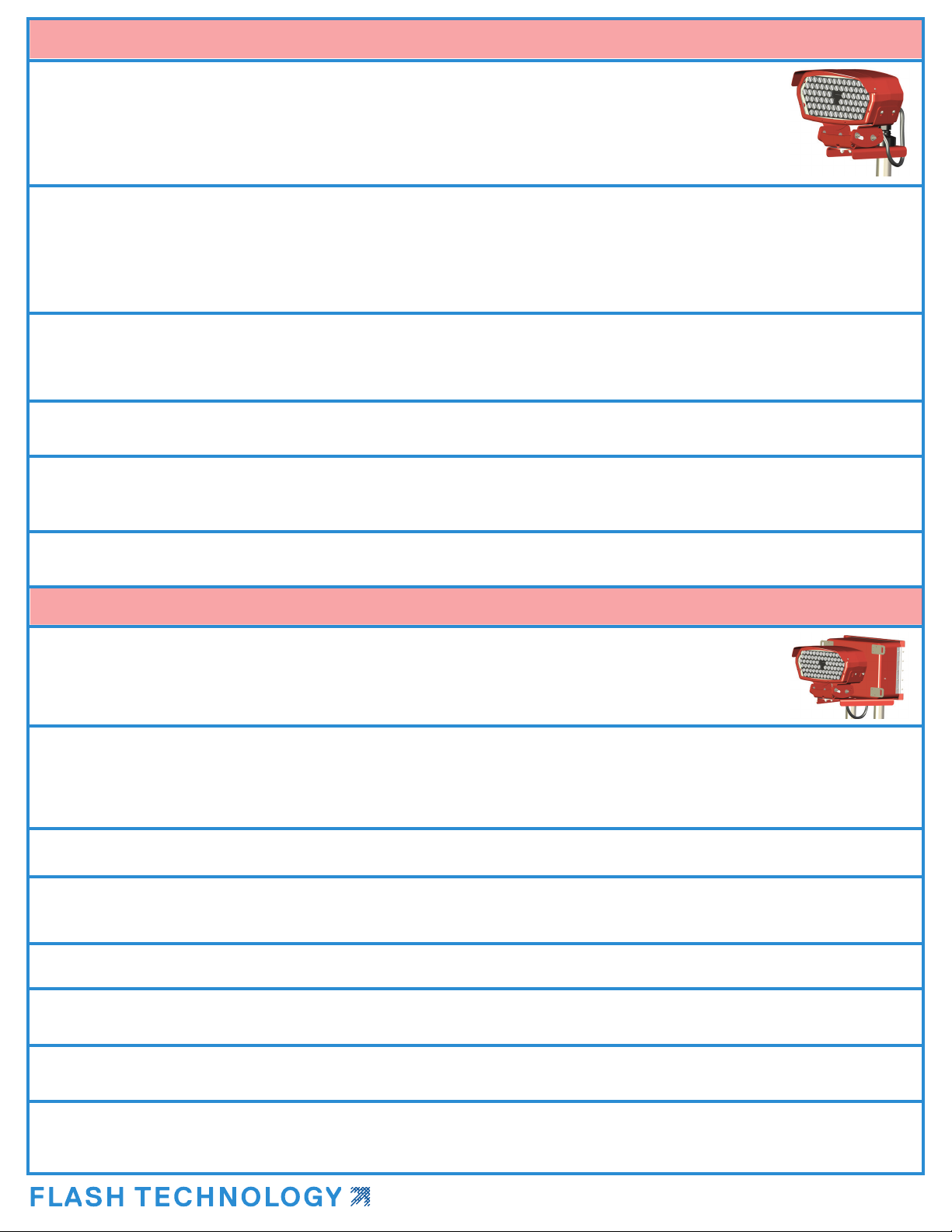
The FH 800(L) comes pre-installed on the remote-mount bracket assembly
FH 800(L)
Back
1
2
2Bubble level
Each FTS 812(L) system includes two LED ashheads and one power converter/controller.
FTS 812(L) REIL/RTIL Installation Quick Start Guide
P/N F7904241 REV A
Call 1-800-821-5825 if additional TECHNICAL or INSTALLATION assistance is needed.
(Monday - Friday, 8a.m - 6p.m CST) | Email:
Remote-mount Assembly Installation Steps
In this assembly, one LED ashead (FH 800(L)) is mounted to a bracket. A single cable will feed from this
assembly to the co-mounted xture. Ensure the installed height does not exceed 34”.
2. Secure the remote-mount assembly to a single mounting pipe (1 x 2” OD).
NOTE! The previous mount can be re-used, if in appropriate condition. Use the included bubble level to ensure the xture is level.
3. Connect the included FH cable to the back of the remote-mount LED FH. Use the twist-lock feature to secure.
4. Route the other cable end (loose cable) through the cable gland and reducer in the remote mounting bracket and through
any conduit/raceway system to the PC 800(L). It is not recommended to leave the cable pigtail end exposed during installation.
5. Prepare the installation surface for the co-mount assembly.
4. Aim each LED FH using the vertical and horizontal leveling guides provided on each assembly.
5. Ensure all connections are tight. Power the system ON and verify user settings and operation (local and remote).
6. After all steps are completed successfully, the installation is nished.
In this assembly, one LED ashhead (FH 800(L)) is mounted to a bracket that also holds one power
converter/controller (PC 800(L)). Ensure the installed height does not exceed 34”.
1. Prepare the entire installation surface and ensure EMT conduit is level. Full detail listed in the product manual (PN F7918000).
NOTE! The FH cable must be installed through the remote-mount bracket cable gland, then through the cable raceway to the PC.
It is not possible to pass the FH cable twist-lock connector through the cable gland in the remote mounting bracket. If this order
is not followed, then the cable will have to be pulled and re-installed in the correct manner.
1. Secure the co-mount assembly and mounting hardware to mounting pipes (2 x 2” OD). Route the remote-mounted ashhead
cables up through the 2” conduit on the right side (as you face the door of the PC enclosure).
NOTE! The previous mounts can be re-used, if in appropriate condition. Use the included bubble level to ensure the xture is level.
3. Install all wiring to the internal terminal block (TB1) of the PC. Including; incoming AC power, remote user connections and FH
cable (power and RS-485). Follow terminal block labels, internal info card and product manual to ensure system is wired properly.
Co-mount Assembly Installation Steps
2. Cut the ashhead cable to an appropriate length.
P/N F7904241 REV A
Other manuals for FTS 812 L
1
This manual suits for next models
3
Table of contents
Popular Safety Equipment manuals by other brands

Siemens
Siemens FDM1101-Rx Technical manual

Guardian Fall Protection
Guardian Fall Protection Diablo 2.0 Tie-Back SRL instruction manual

Honeywell
Honeywell satronic DMG 970 manual

ABS
ABS ABS-Lock Loop installation manual

Parkside
Parkside PFSH 3 A2 Original instructions

Falltech
Falltech DuraTech Class 2 Leading Edge SRL User instruction manual


