Flash 384A User manual

384A DMX CONTROLLER
384ch 2019
User Manual
Instrukcja Obsługi
F9000383

User Manual •Instrukcja Obsługi
IMPORTANT!
Do not point strong light output from other fixtures
at the 384A DMX CONTROLLER 384ch 2019, as
intense illumination can damaged the parts.
2. SAFETY INFORMATION
1. INTRODUCTION
THANK YOU FOR PURCHASING 384A DMX CONTROLLER 384ch 2019. FOR SAFETY
REASONS AND TO ENSURE THE TROUBLE-FREE OPERATION, CAREFULLY READ
THE INSTRUCTIONS.
WARNING!
Figure 2.
Shield or shade the head if necessary.
Please keep this User Manual for future
another user, be sure that they also receive
this instruction booklet.
Unpack and check carefully there is no
transportation damage before using the
Before operating, ensure that the voltage
and frequency of power supply match the
It’s important to ground the yellow/green
conductor to earth in order to avoid electric
shock.
Disconnect main power before servicing
and maintenance.
only, but always by taking its base.
Maximum ambient temperature is: 40
Don’t operate it where the temperature is
higher than this.
In the event of serious operating problem,
carried out by unskilled people can lead to
damage or malfunction. Please contact the
nearest authorized technical assistance
center. Always use the same type spare
parts.
Do not connect the device to any dimmer
pack.
Do not touch any wire during operation
and there might be a hazard of electric
shock.
To prevent or reduce the risk of electrical
rain or moisture.
visibly damaged.

384A DMX CONTROLLER 384ch 2019 •Art No F9000383
4. INSTALLATION
3. PRODUCT INFORMATION
Power supply voltage: 90-240V,
Power Input: DC9-12V, 500 mA
Dimension [cm]: H-7,3 W-52,2 D-18,3
DMX 512/1990 Standard
Controls 24 inteligent lights of up to 16
channels totally 384 channels.
30 banks, each witch 8 scenes, 6 chase,
each witch up to 240 scenes.
Records up to 6 chases with fade time and
speeds.
Weight [kg]: 3kg
Type of packaging: Carton Box
Make sure all necessary cables are
properly connected. Always ensure that
and slipping while operating. Always
ensure that the structure to which you
are attaching the unit is secure and is
able to support a weight of 10 times of
the unit’s weight. Also always use a safety
cable that can hold 12 times of the weight
of the touch of people and has no one pass
by or under it.
4.1 Voltage specification
3.1 Main Features
Input Voltage Total Power Frequency
90-240V 2W 50/60Hz
16 sliders for direct control of channels
MIDI control over banks, chases and
blackout.
Bulit-in microphone for music mode
Auto mode program controlled by fade
time sliders
DMX in/out: 3 pin XLR
LED gooseneck lamp
banks can contain up to 240 steps composed of the saved scenes and in any order. Programs
can be triggered by music, midi,automatically or manually. All chases can be executed at
the same time.
a wheel and LED display indicators for easier navigation of controls and menu functions.
wheel at the same time by means of a programmable wheel.

156
7816
2
3
4
9
18 17
10 11 12
13 14 15
5. OPERATION
2422 25
23
21
5.1 Product Overview (FRONT)
5.2 Product Overview (REAR PANEL)
User Manual •Instrukcja Obsługi

Item Button or Fader Function
1Scanner select button Fixture Selection
2Scanner indicators LEDS Indicates the xtures currently selected
3Scene select button universal bump button representing scene Location
for storage and selection
4Channel faders
For adjusting DMX values, Ch 1-16 can be adjusted
immediately after pressing the respective scanner
Select button
5Program button Used to enter programming mode
6Music/Bank Copy button Used to activate Music mode and as the copy Com-
mand during programming
7LED display window status window display pertinent operational data
8Mode indicator LEDS Provides operating mode status, (manual, Music or
auto)
9Bank Up button Function button to traverse Scene/Steps in Banks
or chases
10 Bank Down button Function button to traverse Scene/Steps in Banks
or chases
11 Tap display button Sets the chase speed by tapping, and toggles
between Values and percentages.
12 Blackout button Sets the shutter or dimmer value of all xtures to
„0” causing all light Output to case
13 Midi/ADD button Activates MIDI external control and also used to
conrm the record/save process
14 Auto/Del button Used to acivated Auto mode and as the delete func-
tion key during programming
15 Chaser buttons Chase memory 1-6
16 Speed fader This will adjust the hold time of a scene or a step
Within a chase
17 Fade-time fader Also considered a cross-fade, sets the interval Time
between pages of control
18 Page Select button In manual mode, press to toggle between pages of
control
21 MIDI input port For external triggering of Banks and Chases using a
MIDI device
22 DMX output connector DMX control signal
23 DC input jack Main power feed
24 USB lamp socket
25 ON/OFF power Switch Turns the controller on and off
384A DMX CONTROLLER 384ch 2019 •Art No F9000383

Common Terms
intelligent light programming.
Blackout is a state by where all lighting
usually on a temporary basis.
DMX-512 is an industry standard
digital communication protocol used in
entertainment lighting equipment. For
more information read Sections „DMX
Primer” and „DMX Control Mode” in the
Appendix.
Fixture refers to your lighting instrument
or other device such as a fogger or dimmer
of which you can control.
Programs are a bunch of scenes stacked
either a single scene or multiple scenes in
sequence.
Scenes are static lighting states.
Sliders also known as faders.
Chases can also be called programs. A chase
consists of a bunch of scenes stacked one
Scanner refers to a lighting instrument
with a pan and tilt mirror; however, in
the I LS-CON controller it can be used to
control any DMX-512 compatible device as
MIDI is a standard for representing musical
information in a digital format. A MIDI
input would provide external triggering
of scenes using midi device such as a midi
keyboard.
Stand Alone
to function independently of an external
controller and usually in sync to music, due
to a built in microphone.
Fade slider is used to adjust the time
between scenes within a chase.
Speed
scene will hold its state. It is also considered
a wait time.
Shutter is a mechanical device in the
intensity of the light output and to strobe.
Patching refers to the process of assigning
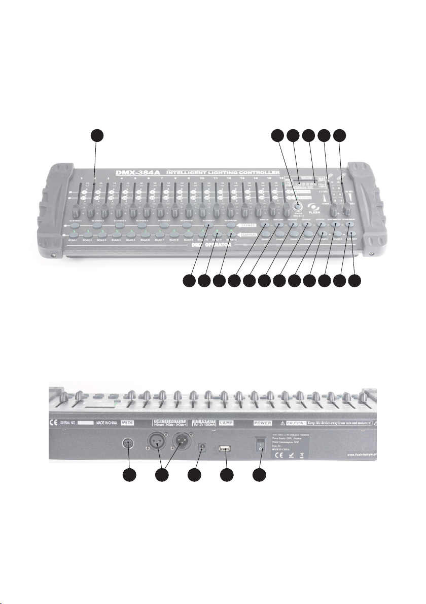
SETTING UP THE SYSTEM
1) Plug the AC to DC power supply to the
system back panel and to the mains outlet.
2) Plug in your DMX cable(s) to your
intelligent lighting as described in the
Primer on DMX see the „DMX Primer”
section in the Appendix of this manual.
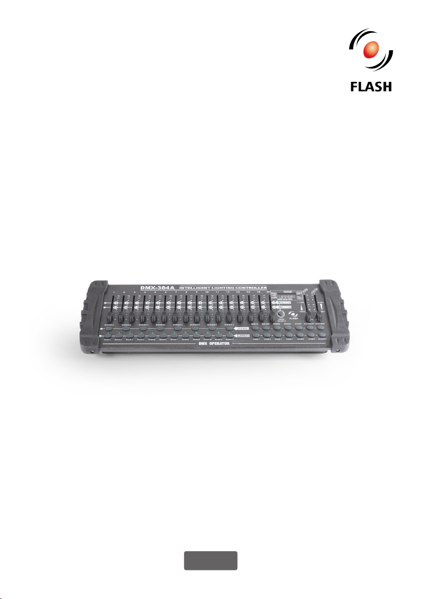
FIXTURE ADDRESSING
corresponding apart.
„SCANNER” buttons on the unit, must be
spaced 16 channels.
Fixture or
Scanner #
Default DMX
Starting
Address
Binary Dipswitch
settings switch to
the „On Position”
1 1 1
2 17 1, 5
3 33 1, 6
4 49 1, 5, 6
5 65 1, 7
6 81 1, 5, 7
7 97 1, 6, 7
8 113 1, 5, 6, 7
9 129 1, 8
10 145 1, 5, 8
11 161 1, 6, 8
12 177 1, 5, 6, 8
User Manual •Instrukcja Obsługi

13 193 1, 7, 8
14 209 1, 5, 7, 8
15 225 1, 6, 7, 8
16 241 1, 5, 6, 7, 8
17 257 1, 9
18 273 1, 5, 9
19 289 1, 6, 9
20 305 1, 5, 6, 9
21 321 1, 7, 9
22 337 1, 5, 7, 9
23 353 1, 6, 7, 9
manual for DMX addressing instructions.
WHEEL ASSIGNMENT
are alike or share the same control
attributes, the DMX-240A allows the user
to assign the wheel the correct pan and
including 16 bit channel assignments. It
also allows the user to re-assign physical
user can combine or unify control of similar
Action:
1) press and hold the PROGRAM button
until the led blinks
2) Press and hold FINE & MODE buttons
together
3) times to access the channel assignment
dmx channel.
3) press a SCANNER button that represents
tilt
4) Use the BANKUP/DOWN buttons to
select pan/tilt
Notes:
All wheels can be reassigned to output on a
Press AUTO/DEL&MODE buttons together
to delete the channel assignment mode.
Action:
5) Press the TAP/DISPLAY button to switch
pages
6) Press and hold MODE button, then
press the SCENES buttons to select the
DMXchannel. AII LEDs will blink.
7) Press and hold FINE & MODE buttons to
exit
Notes:
You can re-assign the DMX channel to all
controller fader channels.
Review wheel assignment or reverse
Action: (Reverse Review)
1) Press and hold FINE & MODE buttons
together to access the wheel assignment
mode
2) press a SCANNER button to select a
scanner
3) Press and hold FINE & MODE buttons
together (2) times to exit
Action: (wheel assignment Review)
1) Press and hold FINE & mode buttons
together (2) times to access the channel
reverse mode
2) press a SCANNER button to select a
scanner
3) Press and hold FINE & MODE buttons to
exit
COPY SCANNER
Example: Copying Scanner 1 into Scanner 2
384A DMX CONTROLLER 384ch 2019 •Art No F9000383

Action:
1) Press and hold SCANNER button # 1.
2) While holding button# 1 press SCANNER
button # 2.
releasing SCANNER button # 2.
Notes:
To save time, you can copy the settings of
one Scanner button to another.
REVERSE CHANNEL OUTPUT
Action:
1) press and hold the PROGRAM button
until the led blinks
2) Press and hold FINE & MODE buttons
together to access the channel assignment
mode ,then press the SCANNER button
3) Use the Bankup/Down buttons to select
pan/tilt
4) Press the TAP/DISPLAY button to switch
between pages
5) press and hold MODE button, then press
the SCENES buttons to select the DMX
channel. AII LEDs will blink.
6) Press and hold FINE & MODE buttons (2)
times to exit
Notes:
You can permanently reverse the output of
any given channel on the controller.
Press AUTO/DEL&MODE buttons together
to delete the reverse channel.
FADE TIME ASSIGN
You can choose whether the boards fade
timeduringsceneexecutionisimplemented
broadly to all output channels or only to
and colors to change quickly while not
Action:
1) Turn OFF the controller.
2) Hold the MODE and TAP DISPLAY
buttons simultaneously.
3) Turn ON the controller.
4) Press the TAP DISPLAY button to toggle
between the two modes. Either ALL CH (all
channels) or ONLY X/Y (Pan & Tilt only)
5) Press MODE and TAP DISPLAY to save
Notes:
ALL CH: All channels ONLY X/Y: Only Pan
& Tilt
Operation
MANUAL MODE
all scanners. You are able to move them
and change attributes by using the channel
faders and wheel.
Action:
1) Press the AUTO DEL button repeatedly
until the MANUAL LED is lit.
2) Select a SCANNER button.
attributes. PAGE/SELECT A/8 button:
Use to switch between fader control of
(A: Ch 1-8 ), (B: Ch 9-16)
TAP DISPLAY button:
Press to toggle the output indicator on the
LCD display between DMX values (0-255)
and percentage (0-100)
Notes:
All changes made while in Manual Mode are
temporary and will not be recorded
REVIEW SCENE OR CHASE
already recorded scenes and chases on the
User Manual •Instrukcja Obsługi

controller. Other wise skip section and go to
programming.
Action: (SCENE Review)
1) Select any one of the 30 banks by pressing
the BANK UP/DOWN buttons.
2) Select a SCENE button (1-8) to review.
attributes.
Action: (CHASE Review)
1) Press any one of the 6 CHASE buttons.
2) Press the TAP DISPLAY button to view
the step number on the display.
3) Press the BANK UP/DOWN buttons
review all scenes in the chase.
Notes:
Make sure you are still in MANUAL Mode.
Programming
scenes (or steps) that will be called up
programs can be created of 8 scenes in each.
ENTERING PROGRAM MODE
1) Press the Program button until the LED
blinks.
CREATE A SCENE
A scene is a static lighting state. Scenes
memories on the controller and each bank
can save 240 scenes total.
Action:
1) Press the PROGRAM button until the
LED blinks.
2) Position SPEED and FADE TIME sliders
all the way down.
3) Select the SCANNERS you wish to include
in your scene.
4) Compose a look by moving the sliders
and wheel.
5) Tap MIDI/REG button.
6) Choose a BANK (01-30) to change if
necessary.
7) Select a SCENES button to store.
8) Repeat steps 3 through 7 as necessary.
8 scenes can be recorded in a Program.
9) To exit program mode, hold the
PROGRAM button.
Notes:
Deselect Blackout if LED is lit.
You can access channels 9~16 by pressing
control.
display will now indicate the Scene number
and Bank number used.
Tip! Press the FINE button, activate
joystick or slider by moving it then use the
Bank Up/Down buttons to change values in
increments of „1” .
Shortcut:Press[PROGRAM]+[SCANNERS]
Adjust[Faders& Wheel]+[BANK]+[SCENE]
+Press [PROGRAM] to store.
RUNNING A PROGRAM
Action:
1) Use BANK UP/DOWN buttons to change
Program banks if necessary.
2) Press the AUTO DEL button repeatedly
until the AUTO LED turns on.
3) Adjust the PROGRAM speed via the
SPEED fader and the loop rate via the FADE
TIME fader.
4) Alternatively you can tap the TAP
384A DMX CONTROLLER 384ch 2019 •Art No F9000383

two taps sets the time between SCENES (up
to 10 minutes).
Notes:
Deselect Blackout if LED is lit.
Also called a Tap-Sync.
CHECK PROGRAM
Action:
1) Press and hold the PROGRAM button
until the LED blinks.
2) Use the BANK UP/DOWN buttons to
select the PROGRAM bank to review.
3) Press the SCENES buttons to review each
scene individually.
EDITING A PROGRAM
Action:
1) Press and hold the PROGRAM button
until the LED blinks.
2) Use BANK UP/DOWN buttons to change
Program banks if necessary.
SCANNERS button.
using the channel faders and wheel.
5) Press the MIDI/REC button to prepare
the save.
6) Select the desired SCENES button to
save.
Notes:
Deselect Blackout if LED is lit.
COPY A PROGRAM
Action:
1) Press and hold the PROGRAM button
until the LED blinks.
2) Use BANK UP/DOWN buttons to select
the PROGRAM bank you will copy.
3) Press the MIDI/REC button to prepare
the copy.
4) Use BANK UP/DOWN buttons to select
the destination PROGRAM bank.
5) Press the MUSIC BANK COPY button to
execute the copy. All LEDs on the controller
will blink.
Notes:
All 8 scenes in a Program bank will be
copied.
Chase Programming
A chase is created by using previously
created scenes. Scenes become steps in a
chase and can be arranged in any order
you choose. It is highly recommended that
time; you delete all chases from memory.
See „Delete All Chases” for instructions.
CREATE A CHASE
A Chase can contain 240 scenes as steps.
interchangeably.
Action:
1) Press the PROGRAM button until the
LED blinks.
2) Press the CHASE (1-6) button you wish
to program.
3) Change BANK if necessary to locate a
scene.
4) Select the SCENE to insert.
5) Tap the MIDI/REC button to store.
6) Repeat steps 3-5 to add additional
steps in the chase. Up to 240 steps can be
recorded.
7) Press and hold the PROGRAM button to
save the chase.
RUNNING A CHASE
Action:
1) Press a CHASE button then press the
AUTO DEL button.
2) Adjust the Chase speed by tapping the
TAP DISPLAY button twice at a rate of your
choosing.
User Manual •Instrukcja Obsługi

Notes:
speed (up to 10 minutes)
CHECKING A CHASE
Action:
1) Press and hold the PROGRAM button
until the LED is lit.
2) Select the desired CHASE button.
3) Press the TAP DISPLAY button to switch
the LCD display to steps.
4) Review each scene/step individually by
using the BANK UP/DOWN buttons.
EDIT CHASE
(COPY BANK INTO CHASE)
Action:
1) Press and hold the PROGRAM button to
enter programming mode.
2) Press the desired CHASE button.
3) Select the BANK to be copied using the
BANK UP/DOWN buttons.
4) Press MUSIC/BANK COPY button to
prepare copy.
5) Press MIDI/REC button to copy the
bank. All LEDs will blink.
EDIT CHASE (COPY SCENE INTO CHASE)
Action:
1) Press and hold the PROGRAM button to
enter programming mode.
2) Press the desired CHASE button.
3) Select the BANK that contains the scene
to be copied using the BANK UP/DOWN
buttons.
4) Press the SCENE button that corresponds
to the scene to be copied.
5) Press MIDI/REG button to copy the
scene. All LEDs will blink.
EDIT CHASE (INSERT SCENE INTO A
CHASE)
Action:
1) Press and hold the PROGRAM button to
enter programming mode.
2) Press the desired CHASE button.
3) Press the TAP DISPLAY to switch the LCD
display to steps view.
4) Use the BANK UP/DOWN buttons to
navigate steps and locate the insert point of
the new scene.
5) Press MIDI/REC button to prepare the
insert.
6) Use the BANK UP/DOWN button to
locate the SCENE.
7) Press the SCENE button that corresponds
to the scene to be inserted.
8) Press MIDI/REC button to insert the
scene. All LEDs will blink.
Notes:
I.e. To insert a scene between Steps 05 and
06 navigate using BANK buttons until the
display reads STEP05.
DELETE A SCENE IN A CHASE
Action:
1) Press and hold the PROGRAM button to
enter programming mode.
2. Press the desired CHASE button that
contains the scene to be deleted.
3) Press the TAP DISPLAY button to switch
the LCD display to steps.
4) Select the scene/step to be deleted using
the BANK UP/DOWN buttons.
5) Press AUTO DEL button to delete the
step/scene. All LEDs will blink.
DELETE A CHASE
Action:
1) Press and hold the PROGRAM button to
enter programming mode.
384A DMX CONTROLLER 384ch 2019 •Art No F9000383

2. Press the CHASE button (1-6) to be
deleted.
3) Press and hold AUTO DEL button and
the respective CHASE button to delete the
chase. All LEDs will blink.
DELETE ALL CHASE PROGRAMS
CAUTION!
individual scenes and program banks will
be preserved.
Action:
1) Turn OFF controller.
2) Press and hold the BANK DOWN button
and the AUTO DEL button while turning
ON the controller.
3) All LEDs will blink.
Scene Programming (Steps)
INSERT A SCENE
Action:
1) Press and hold the PROGRAM button to
enter programming mode.
2) Press the desired CHASE button.
3) Press the TAP DISPLAY to switch the LCD
display to steps view.
4) Use the BANK UP/DOWN buttons to
navigate steps and locate the insert point of
the new scene.
5) Press MIDI/REC button to prepare the
insert.
6) Use the BANK UP/DOWN button to
locate the SCENE.
7) Press the SCENE button that corresponds
to the scene to be inserted.
8) Press MIDI/REC button to insert the
scene. All LEDs will blink.
Notes:
1.e. To insert a scene between Steps 05 and
06 navigate using BANK buttons until the
display reads STEP05.
COPY A SCENE
Action:
1) Press and hold the PROGRAM button to
enter programming mode.
2) Select the BANK that contains the scene
to be copied using the BANK UP/DOWN
buttons.
3) Press the SCENE button that corresponds
to the scene to be copied.
4) Press MIDI/REG button to copy the
scene.
5) Select the destination BANK that contains
the scene memory to record onto using the
BANK UP/DOWN buttons.
6) Press the desired SCENE button to
complete copy. All LEDs will blink.
DELETE A SCENE
Action:
1) Press and hold the PROGRAM button to
enter programming mode.
2) Select the BANK that contains the scene
to be deleted by using the BANK UP/DOWN
buttons.
3) Press and hold the AUTO DEL button.
4) Press the SCENE button that corresponds
to the scene you want to delete. All LEDs
will blink.
Notes:
When deleting a scene the physical location
is not removed, however, all 192 DMX
channels available to the scene will be set to
value 0.
User Manual •Instrukcja Obsługi

DELETE ALL SCENES
Action:
1) Press and hold the PROGR AM button
and the BANK DOWN button while turning
2) Turn the controller back on.
Notes:
CAUTION!
data will be set to 0.
Playback
RUNNING IN SOUND-MODE
Action:
1) Press the MUSIC BANK COPY button
until the MUSIC LED turns on.
2) Select the program BANK to run in sound
active mode using the BANK UP/DOWN
buttons.
3) Alternatively you can press a single
CHASE button (1~6) or several CHASE
buttons in sequence and all selected chases
will loop in the order selected.
4) You can adjust the duration time using
the FADE TIME fader.
Notes:
In the Sound mode, programs will be
triggered by the sound using its built-in
microphone.
Multiple chases selected will loop and run
in the order originally selected.
RUNNING IN AUTO-MODE
Action:
1) Press the AUTO DEL button until the
AUTO LED turns on.
2) If a CHASE button is not pressed the
controller will automatically run a BANK
program.
3) Change BANK programs by using BANK
UP/DOWN buttons.
4) Alternatively you can press a single
CHASE button (1~6) or several CHASE
buttons in sequence and all selected chases
will loop in the order selected.
5) You can adjust the time between steps by
moving the SPEED fader and the duration
of the step by moving
the FADE TIME fader.
Notes:
In the Auto mode, programs will be
triggered by controllers fade and speed
time as set on the faders.
Multiple chases selected will loop and run
in the order originally selected.
RUN MULTIPLE CHASES
SIMULTANEOUSLY
Action:
1) Press and hold AUTO DEL button.
2) While holding down AUTO DEL, in
succession press and release each CHASE
you would like to run simultaneously.
Notes:
IMPORTANT!
scenes running simultaneously that control
creating individual color and gobo chases.
BLACKOUT
Midi Operation
I commands on the MIDI channel which
it is set to full stop. All MIDI control is
performed using Note on commands. All
other MIDI instructions are ignored. To
stop a chase, send the blackout on note.
Action:
384A DMX CONTROLLER 384ch 2019 •Art No F9000383

1 )Press and hold the MIDI/REC button for
about 3 seconds.
2) Select the MIDI control channel (1~16) via
the BANK UP/DOWN buttons to set.
3) Press and hold the MIDI/REC button for
3 seconds to save settings.
4) To release MIDI control, press any other
button except the BANK buttons during
step 2.
Notes:
receive MIDI note commands.
MIDI NOTE FUNCTION (TURN ON/OFF)
00 to 07 Scenes 1-8 in BANK 1
08 to 15 Scenes 1-8 in BANK 2
16 to 23 Scenes 1-8 in BANK 3
24 to 31 Scenes 1-8 in BANK 4
32 to 39 Scenes 1-8 in BANK 5
40 to 47 Scenes 1-8 in BANK 6
48 to 55 Scenes 1-8 in BANK 7
56 to 63 Scenes 1-8 in BANK 8
64 to 71 Scenes 1-8 in BANK 9
72 to 79 Scenes 1-8 in BANK 10
80 to 87 Scenes 1-8 in BANK 11
88 to 95 Scenes 1-8 in BANK 12
96 to 103 Scenes 1-8 in BANK 13
104 to 111 Scenes 1-8 in BANK 14
112 to 119 Scenes 1-8 in BANK 15
120 Chase 1
121 Chase 2
122 Chase 3
123 Chase 4
124 Chase 5
125 Chase 6
126 BLACKOUT
3.8 Data Transfer
It is possible to transfer the programs
stored in one DMX-240A controller to
another. Connect from the DMX output
of the programmed controller to the DMX
input of the other.
Action:
SCANNER buttons 2, 3 and SCENE button 1
then turn unit back On.
and hold SCANNER buttons 8, 9 and
SCENE button 2 then turn unit back On.
3) Both units are now ready to transmit
and receive. Press SCENE buttons 7 & 8
simult aneously on Source unit to begin
transmission.
Notes:
indicates it is ready to transmit data.
this indicates it is ready to receive data
transmission.
User Manual •Instrukcja Obsługi

OSTRZEŻENIE!
WAŻNE!
Rysunek 2.
240A DMX CONTROLLER 240ch 2019. Ze
1. WPROWADZENIE
2. ZASADY BEZPIECZENSTWA
przez wykwalifikowany personel, aby
do sieci elektrycznej.
stabilnych konstrukcjach.
w dobrze wentylowanym pomieszczeniu, w
384A DMX CONTROLLER 384ch 2019 •Art No F9000383

3. INFORMACJA O PRODUKCIE
3.1 Główne cechy
4. INSTALACJA
obok ani pod nim.
4.1 Specyfikacja zasilania
Napięcie Zasilania Pobór Mocy Częstotliwość zasilania
90-240V 2W 50/60Hz
Zasilanie: 90-240V,
Wymiary [cm]: H-7,3 W-52 D-18 18,3 cm
Waga[kg]: 3 kg
Pakowanie: Karton
DMX 512/1990 Standard
-
-
-
mi” i zaciemnieniem.
Wbudowany mikrofon dla trybu mu-
zycznego
Program trybu automatycznego sterowa-
XLR
User Manual •Instrukcja Obsługi

156
7816
2
3
4
9
18 17
10 11 12
13 14 15
2422 25
23
21
5.1 Product Overview (FRONT)
5.2 Product Overview (REAR PANEL)
384A DMX CONTROLLER 384ch 2019 •Art No F9000383

User Manual •Instrukcja Obsługi
Przycisk lub Suwak Funkcja
1 Przycisk wyboru skanera Wybór urządzenia
2 Wskaźniki skanera Diody LED Wskazują aktualnie wybrane urządzenia
3 Przycisk wyboru sceny Uniwersalny przycisk wypukłości reprezentujący lokalizację
sceny do przechowywania i wyboru
4 Suwaki Kanałów Aby ustawić wartości DMX, kanały 1-16 można regulować
natychmiast po naciśnięciu odpowiedniego przycisku
wyboru skanera
5 Przycisk programu Służy do wejścia w tryb programowania
6 Przycisk Music / Bank Copy Służy do włączania trybu muzycznego i jako polecenie
kopiowania podczas programowania
7 Okno stanu wyświetlacza LED wyświetla istotne dane operacyjne
8 Dioda LED wskaźnika trybu Informuje o stanie trybu pracy
(ręczny, muzyczny lub automatyczny)
9 Przycisk Bank Up Przycisk funkcyjny do przechodzenia przez Scenę / Kroki
w Bankach lub Chase’ach
10 Przycisk Bank Down Przycisk funkcyjny do przechodzenia przez Scenę / Kroki
w Bankach lub Chase’ach
11 Przycisk ekranu dotykowego Ustawia prędkość chase przez stukanie i przełącza
pomiędzy Wartościami i procentami.
12 Przycisk Blackout Ustawia wartość migawki lub dimmera wszystkich urządzeń
na „0”, powodując, że całe wyjście światła jest ustawione
13 Przycisk Midi/ADD Aktywuje zewnętrzne sterowanie MIDI i służy również do
potwierdzania procesu nagrywania/zapisywania
14 Przycisk Auto/Del Służy do włączania trybu Auto i jako przycisk funkcji
usuwania podczas programowania
15 Przyciski Chasera Pamięć Chase 1-6
16 Suwak szybkości Służy do regulacji czasu wstrzymania sceny lub kroku
w ramach chase
17 Fader czasu przejścia Uważany również za przenikanie, ustawia interwał Czas
między stronami sterowania
18 Przycisk wyboru strony W trybie ręcznym naciśnij, aby przełączać między stronami
kontroli
21 Port wejściowy MIDI Do zewnętrznego wyzwalania banków i chase’ów
za pomocą urządzenia MIDI
22 Złącze wyjściowe DMX Sygnał sterujący DMX
23 Gniazdo wejściowe prądu
stałego
Zasilanie główne
24 gniazdo lampy USB
25 Włącznik/wyłącznik
zasilania
Włącza i wyłącza sterownik

Wyjaśnienie funkcji
-
wane terminy w programowaniu inteli-
Blackout -
-
czasowo.
DMX-512
-
Fixture
Programs
-
Scenes
Sliders
Chases
jedna po drugiej.
Scanner-
tleniowego z lustrem obrotowo-uchylnym;
-
dzeniem kompatybilnym z DMX-512 jako
MIDI to standard przedstawiania infor-
macji muzycznych w formacie cyfrowym.
-
takiego jak klawiatura midi.
Stand Alone
-
-
wanemu mikrofonowi.
Fade
scenami w ramach chase.
Speed
Shutter
-
KONFIGURACJA SYSTEMU
-
nelu systemu i do gniazda sieciowego.
-
-
wiedniej instrukcji opraw.
ADRESOWANIE URZĄDZENIA
DMX-240A jest zaprogramowany do ste-
-
-
Urządze-
nie lub
skaner #
Domyślny adres
początkowy
DMX
Ustawienie przełą-
czników binarnych
przełączają się w
pozycję „On Position”
1 1 1
2 17 1, 5
3 33 1, 6
4 49 1, 5, 6
5 65 1, 7
6 81 1, 5, 7
7 97 1, 6, 7
8 113 1, 5, 6, 7
384A DMX CONTROLLER 384ch 2019 •Art No F9000383

9 129 1, 8
10 145 1, 5, 8
11 161 1, 6, 8
12 177 1, 5, 6, 8
13 193 1, 7, 8
14 209 1, 5, 7, 8
15 225 1, 6, 7, 8
16 241 1, 5, 6, 7, 8
17 257 1, 9
18 273 1, 5, 9
19 289 1, 6, 9
20 305 1, 5, 6, 9
21 321 1, 7, 9
22 337 1, 5, 7, 9
23 353 1, 6, 7, 9
PRZYDZIELANIE „KÓŁ”
-
te same atrybuty sterowania, DMX-240A
-
-
-
-
Action:
-
-
-
kanale DMX.
-
Notes:
-
Action:
Notes:
Sprawdź przypisanie kół lub cofnij
Action: (Reverse Review)
-
skaner
Action:
skaner
User Manual •Instrukcja Obsługi
Table of contents
Languages:
Other Flash Dj Equipment manuals

Flash
Flash F7100520 User manual

Flash
Flash DIAMOND ROTO PRISM User manual

Flash
Flash F7100545 User manual

Flash
Flash LED MOVING HEAD 60W User manual

Flash
Flash F7000251 User manual

Flash
Flash F7100305 User manual

Flash
Flash F7100310 User manual

Flash
Flash F7100109 Product guide

Flash
Flash F7300248 User manual

Flash
Flash F7100495 User manual

Flash
Flash F7000643 User manual

Flash
Flash F7100090 User manual

Flash
Flash LED MOONTH FLOWER LIGHT User manual

Flash
Flash F7100322 User manual

Flash
Flash F71000269 User manual

Flash
Flash LED FRAME 700W User manual

Flash
Flash F7100077 User manual

Flash
Flash F7300240 User manual

Flash
Flash F7100098 User manual

Flash
Flash F7300215 User manual