manuals.online logo
Brands
  1. Home
  2. •
  3. Brands
  4. •
  5. FlashLogic
  6. •
  7. Remote Starter
  8. •
  9. FlashLogic FLRSGM7 User manual

FlashLogic FLRSGM7 User manual

Other manuals for FLRSGM7

1

Other FlashLogic Remote Starter manuals
FlashLogic FLC-AL-GM2-EN User manual

FlashLogic

FlashLogic FLC-AL-GM2-EN User manual
FlashLogic FLRSCH7 User manual

FlashLogic

FlashLogic FLRSCH7 User manual
FlashLogic FLC-AL(DL)-CH4-EN User manual
FlashLogic

FlashLogic FLC-AL(DL)-CH4-EN User manual

FlashLogic FLRSCH5 User manual

FlashLogic

FlashLogic FLRSCH5 User manual
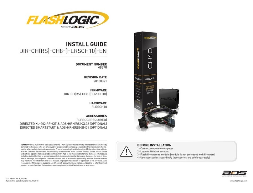
FlashLogic DIR-CH8 User manual

FlashLogic

FlashLogic DIR-CH8 User manual
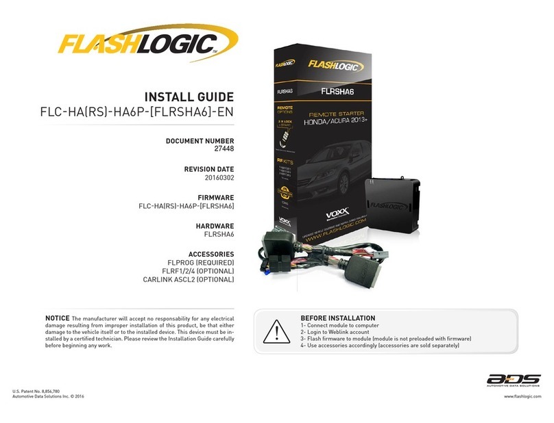
FlashLogic FLRSHA6 User manual

FlashLogic

FlashLogic FLRSHA6 User manual
FlashLogic FLC-DL-GM2 User manual

FlashLogic

FlashLogic FLC-DL-GM2 User manual
FlashLogic FLRSGM10 User manual

FlashLogic

FlashLogic FLRSGM10 User manual

FlashLogic FLC-CH(RS)-CH5-[FLRSCH5]-EN User manual
FlashLogic

FlashLogic FLC-CH(RS)-CH5-[FLRSCH5]-EN User manual

FlashLogic FLRSGM7 User manual

FlashLogic

FlashLogic FLRSGM7 User manual

FlashLogic FLC-AL-CH4 User manual

FlashLogic

FlashLogic FLC-AL-CH4 User manual

Popular Remote Starter manuals by other brands
FamilyTool FMT002JST instruction manual

FamilyTool

FamilyTool FMT002JST instruction manual

PowerJump LMD-021 user manual

PowerJump

PowerJump LMD-021 user manual

AstroStart 803U user manual

AstroStart

AstroStart 803U user manual

Durite 0-649-20 Leaflet

Durite

Durite 0-649-20 Leaflet

Linear ACCESS AK-21 Installation and programming instructions

Linear

Linear ACCESS AK-21 Installation and programming instructions

Soundstream TARANTULA RS.2 installation guide

Soundstream

Soundstream TARANTULA RS.2 installation guide

Jaycar Electronics MB3752 instruction manual
Jaycar Electronics

Jaycar Electronics MB3752 instruction manual

Ultra Start 72 Series owner's manual

Ultra Start

Ultra Start 72 Series owner's manual
ADS FLASHLOGIC FLRSVW1 Product guide

ADS

ADS FLASHLOGIC FLRSVW1 Product guide
Black Widow Security BW RAS 400 installation manual
Black Widow Security

Black Widow Security BW RAS 400 installation manual

Vector Power City DK080706 Owner's manual & warranty
Vector

Vector Power City DK080706 Owner's manual & warranty

Code Alarm CA-535 owner's manual

Code Alarm

Code Alarm CA-535 owner's manual
EINHELL EGS 3600 Directions for use

EINHELL

EINHELL EGS 3600 Directions for use
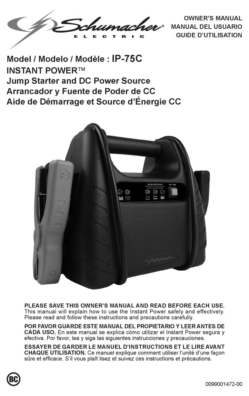
Schumacher INSTANT POWER IP-75C owner's manual
Schumacher

Schumacher INSTANT POWER IP-75C owner's manual

EINHELL BT-PS 1000 Directions for use

EINHELL

EINHELL BT-PS 1000 Directions for use
Mazda 0000-8F-H28 installation instructions

Mazda

Mazda 0000-8F-H28 installation instructions

DEI 450ESP owner's guide

DEI

DEI 450ESP owner's guide

Directed Electronics AutoCommand 28624TN Owner's installation guide
Directed Electronics

Directed Electronics AutoCommand 28624TN Owner's installation guide

manuals.online logo
manuals.online logoBrands
  • About & Mission
  • Contact us
  • Privacy Policy
  • Terms and Conditions

Copyright 2025 Manuals.Online. All Rights Reserved.

REVISION DATE
20130911
DOCUMENT NUMBER
NOTICE The manufacturer will accept no responsability for any electrical
damage resulting from improper installation of this product, be that either
damage to the vehicle itself or to the installed device. This device must be in-
stalled by a certified technician. Please review the Installation Guide carefully
before beginning any work.
BEFORE INSTALLATION
1- Connect module to computer
2- Login to Weblink account
3- Flash firmware to module (module is not preloaded with firmware)
4- Use accessories accordingly (accessories are sold separately)
INSTALL GUIDE
FLCGMRSGM7EN
HARDWARE
FLRSGM7
FIRMWARE
FLCGMRSGM7
www.flashlogic.comAutomotive Data Solutions Inc. © 2013
ACCESSORIES
FLPROG REQUIRED
FLRF2 REQUIRED
CARLINK ASCL2 OPTIONAL
12028
VEHICLE LIST - 1 OF 1
MAKE
MODEL
YEAR
INSTALL TYPE
FEATURES
DATA IMMOBILIZER BYPASS
PRIORITY UNLOCK
DOOR LOCK
DOOR UNLOCK
ARM OEM ALARM
DISARM OEM ALARM
TRUNK/HATCH RELEASE
DOOR STATUS OUTPUT
TRUNK STATUS OUTPUT
BRAKE PEDAL STATUS OUTPUT
TACHOMETER OUTPUT
DATA/MUX STARTER CTRL
HOOD STATUS OUTPUT*
PARKING LIGHT CTRL
RAP SHUTDOWN CTRL
BUICK
Encore Flip-Key AT 13 1 • • • • • • • • • • • • • •
LaCrosse Flip-Key AT 10-13 1 • • • • • • • • • • • • • • •
Regal Flip-Key AT 11-13 1 • • • • • • • • • • • • • • •
Verano Flip-Key AT 12-13 1 • • • • • • • • • • • • • • •
CHEVROLET
Camaro Flip-Key AT 10-13 1 • • • • • • • • • • • • • • •
Cruze Flip-Key AT 10-14 1 • • • • • • • • • • • • • • •
Equinox Flip-Key AT 10-13 1 • • • • • • • • • • • • • •
Impala AT Flip-Key 14 1 • • • • • • • • • • • • • • •
Malibu Flip-Key AT 13 1 • • • • • • • • • • • • • • •
Orlando Flip-Key AT 11-13 1 • • • • • • • • • • • • • •
Sonic Hatchback AT Flip-Key 12-13 1 • • • • • • • • • • • • • •
Sonic Sedan AT Flip-Key 12-13 1 • • • • • • • • • • • • • • •
Trax Flip-Key AT 13 1 • • • • • • • • • • • • • •
GMC
Terrain Flip-Key AT 10-13 1 • • • • • • • • • • • • • •
* Available only if vehicle is equipped with factory hood switch.
www.flashlogic.comAutomotive Data Solutions Inc. © 2013
PAGE 2 OF 14
• 20130911
FLCGMRSGM7EN
DOC.: #12028
TYPE 1 - WIRE CHART - 1 OF 1
MAKE
MODEL
YEAR
WIRE
DESCRIPTION
CONNECTOR
NAME
CONNECTOR
COLOR
CONNECTOR
TYPE
POSITION
WIRE
COLOR
POLARITY
MODULE
LOCATION
COMPONENT
LOCATOR
BUICK
Encore
AT 13 Swc ~ ~ 16 pin 01 Green (DATA) OBDII ~
Parking Light ~ ~ ~ ~ Green/Gray (-) Light switch ~
LaCrosse
AT 10 Swc ~ ~ 16 pin 01 Green (DATA) OBDII ~
Parking Light ~ ~ ~ ~ LtBlue (-) Light switch ~
LaCrosse
AT 11-13 Swc ~ ~ 16 pin 01 Green (DATA) OBDII ~
Parking Light ~ ~ ~ ~ LtGreen (-) Light switch ~
Regal
AT *11 Swc ~ ~ 16 pin 01 Green (DATA) OBDII ~
Parking Light ~ ~ ~ ~ Green/Gray (-) Light switch ~
Regal
AT
**11-
13
Swc ~ ~ 16 pin 01 Green (DATA) OBDII ~
Parking Light ~ ~ ~ ~ Green/Gray (-) Light switch ~
Verano
AT 12-13 Swc ~ ~ 16 pin 01 Green (DATA) OBDII ~
Parking Light ~ ~ ~ ~ Green/Gray (-) Light switch ~
CHEVROLET
Camaro
AT 10-13 Swc ~ ~ 16 pin 01 Green (DATA) OBDII ~
Parking Light ~ ~ ~ ~ LtBlue (-) Light switch ~
Cruze
AT 10-14 Swc ~ ~ 16 pin 01 Green (DATA) OBDII ~
Parking Light ~ ~ ~ ~ Green/Gray (-) Light switch ~
Equinox
AT 10-13 Swc ~ ~ 16 pin 01 Green (DATA) OBDII ~
Parking Light ~ ~ ~ ~ LtBlue (-) Light switch ~
Impala
AT 14 Swc ~ ~ 16 pin 01 Green (DATA) OBDII ~
Parking Light ~ ~ ~ ~ LtGreen/Gray (-) Light switch ~
Malibu
AT 13 Swc ~ ~ 16 pin 01 Green (DATA) OBDII ~
Parking Light ~ ~ ~ ~ Green/Gray (-) Light switch ~
Orlando
AT 11-13 Swc ~ ~ 16 pin 01 Green (DATA) OBDII ~
Parking Light ~ ~ ~ ~ Green/Gray (-) Light switch ~
Sonic
AT 12-13 Swc ~ ~ 16 pin 01 Green (DATA) OBDII ~
Parking Light ~ ~ ~ ~ Green/Gray (-) Light switch ~
Trax
AT 13 Swc ~ ~ 16 pin 01 Green (DATA) OBDII ~
Parking Light ~ ~ ~ ~ Green/Gray (-) Light switch ~
GMC
Terrain
AT 10-13 Swc ~ ~ 16 pin 01 Green (DATA) OBDII ~
Parking Light ~ ~ ~ ~ LtBlue (-) Light switch ~
* Early production.
** Late production.
www.flashlogic.comAutomotive Data Solutions Inc. © 2013
PAGE 3 OF 14
• 20130911
FLCGMRSGM7EN
DOC.: #12028
MS1MS1
MS2MS2 B1
B2
VS4VS4
VS3VS3
A
B
7
9
3
10
8
11
13
14
12
15
17
18
19
20
16
6
4
1
2
5
3
6
4
1
2
5
C
7
9
3
10
8
11
12
6
4
1
2
5
B1
A1
A2
B2
OBDII
10 11 12 13 14 15 16
12345678
9
1
C
B
A
D
G
F
E
VS2VS2
VS1VS1
A1
A2
PK3 CONNECTOR
PK3 HARNESS
GREEN/WHITE - SWC (DATA) OUTPUT
PARKING LIGHT (-)
SWC (DATA) - 01
01 BROWN/BLACK - PARKING LIGHT (-) OUTPUT
02 GRAY (NC)
TYPE 1 - WIRING DIAGRAM - 1 OF 2
VEHICLE IGNITION SWITCH
OBDII CONNECTOR
VEHICLE
MODULE
HORN (-)
11 GRAY/GREEN - HORN (-) OUTPUT
OPTIONAL
IGNITION CONNECTOR
IGNITION HARNESS
www.flashlogic.comAutomotive Data Solutions Inc. © 2013
PAGE 4 OF 14
• 20130911
FLCGMRSGM7EN
DOC.: #12028
2
1
3
4
D
7
9
3
10
8
6
4
1
2
5
G
C
B
A
D
G
F
E
G
F
2
1
3
4
04 GRAY/WHITE - HOOD STATUS (-) INPUT AFTERMARKET HOOD SWITCH (-)
WITHOUT OEM HOOD SWITCH:
INSTALL AND CONNECT TO
AFTERMARKET HODD SWITCH
TYPE 1 - WIRING DIAGRAM - 2 OF 2
03 GRAY/BLACK (NC)
VEHICLE
RF KIT
MODULE
TELEMATIC
www.flashlogic.comAutomotive Data Solutions Inc. © 2013
PAGE 5 OF 14
• 20130911
FLCGMRSGM7EN
DOC.: #12028
01
OFF
ACC ON
START
02
OFF
ACC ON
START
03
04
OFF
ACC ON
START
05
OFF
ACC ON
START
06
07
OFF
ACC ON
START
08
OFF
ACC ON
START
09
10
OFF
ACC ON
START
11
OFF
ACC ON
START
12
OFF
ACC ON
START
13
OFF
ACC ON
START
14
15
OFF
ACC ON
START
16
MODULE PROGRAMMING PROCEDURE - 1 OF 1
Insert key into ignition.
Turn key to ON position.
Wait, LED will flash GREEN rapidly.
Turn key to OFF position.
Remove key.
LED will turn solid RED.
Insert key into ignition.
Turn key to ON position.
LED will turn OFF.
Turn key to OFF position.
Remove key.
Insert key into ignition.
Turn key to ON position.
Wait, LED will turn solid GREEN for 2 seconds.
Turn key to OFF position.
Module Programming Procedure completed.
www.flashlogic.comAutomotive Data Solutions Inc. © 2013
PAGE 6 OF 14
• 20130911
FLCGMRSGM7EN
DOC.: #12028
>>
01
OFF
ACC ON
START
02
03
OFF
ACC ON
START
OFF
5x
04
05
OFF
ACC ON
START
06
OFF
ACC ON
START
07
>>
VALET MODE PROGRAMMING PROCEDURE - 1 OF 1
NOTE: In Valet Mode, the Remote starter is not
functional. Keyless entry, Lock and Unlock will
remain functional. See RF kit user manual for
alternate valet mode programming.
Insert key into ignition.
Time restriction. Complete next step within 7
seconds.
Turn key to OFF position then to ON position
five times [5x] rapidly.
Wait, LED 1 will turn solid RED for 2 seconds.
Turn key to OFF position.
Remove key.
Valet Mode Programming Procedure
completed.
To exit valet mode: repeat steps 1 to 6.
www.flashlogic.comAutomotive Data Solutions Inc. © 2013
PAGE 7 OF 14
• 20130911
FLCGMRSGM7EN
DOC.: #12028
AFTERMARKET REMOTE PROGRAMMING - 1 OF 1
AFTERMARKET REMOTE PROGRAMMING:
NOTES
I All aftermarket remotes must be programmed to the
RF-Kit.
Refer to the RF-Kit user guide for aftermarket remote
features and programming procedures.
www.flashlogic.comAutomotive Data Solutions Inc. © 2013
PAGE 8 OF 14
• 20130911
FLCGMRSGM7EN
DOC.: #12028
>>
>>
>>
01
OFF
ACC ON
START
02
03 [X]
04
05 [Y]
06
07 [Z]
08 [Z]
09
10
11 [Y]
12
13
14
>>
MODULE NAVIGATION PROCEDURE - 1 OF 1
It is mandatory to exit the Module Navigation
at the end of this procedure. Failure to exit the
Module Navigation will drain vehicle battery.
To exit the Module Navigation at any time:
Follow STEP 13.
Module must be programmed to the vehicle.
Use the Module Navigation Chart on the next
page.
Set ignition to OFF position.
TO ACCESS THE MENUS: Press and hold
programming button until LED 1 turns solid
GREEN.
IN THE MENUS: Press the programming
button as many times as the menu number
indicates. LED 1 will flash GREEN an equal
amount of times continuously.
TO ACCESS THE OPTIONS: Press and hold
programming button until LED 1 turns solid
RED.
IN THE OPTIONS: Press the programming
button as many times as the option number
indicates. LED 1 will flash RED an equal
amount of times continuously.
TO ACCESS THE SETTINGS: Press and hold
programming button until LED 1 turns solid
GREEN.
LED 1 will flash GREEN as many times as
the current (or default) setting number,
continuously.
IN THE SETTINGS: Press the programming
button as many times as necessary to access
your setting. LED 1 will flash GREEN an equal
amount of times continuously.
To return to the MENUS: exit the Module
Navigation and redo the Module Navigation
Procedure.
To save and return to the OPTIONS: Press and
hold programming button until LED 1 turns
solid RED.
LED 1 will flash RED as many times as the
current option number continuously.
Configure every other setting and proceed to
step 13.
MANDATORY: EXIT MODULE NAVIGATION.
Press and hold programming button for 7
seconds. LED 1 will flash RED rapidly. Release
programming button. LED 1 will turn OFF.
Module navigation completed.
Failure to exit the Module Navigation will drain
vehicle battery.
www.flashlogic.comAutomotive Data Solutions Inc. © 2013
PAGE 9 OF 14
• 20130911
FLCGMRSGM7EN
DOC.: #12028
MODULE NAVIGATION CHART - 1 OF 2
MODULE NAVIGATION CHART:
NOTES
[X] MENUS
[Y] OPTIONS
[Z] SETTINGS
I Default settings are listed in bold.
01 CONFIGURATION
01 DISARM/UNLOCK BEFORE START 01 OFF
II Make sure the option is covered on the vehicle before
attempting to change the setting.
02 ON
02 RELOCK AFTER START 01 OFF
02 ON
03 RELOCK AFTER SHUTDOWN 01 OFF
02 ON
04 FORCE UNLOCK ALL ON FIRST PRESS 01 OFF
02 ON
05 TAKEOVER 01 ENABLE
02 DISABLE*
06 N/A 01 N/A
07 N/A 01 N/A
08 MODULE RUN TIME
01 03 MIN
02 05 MIN
03 10 MIN
04 15 MIN
05 25 MIN
06 30 MIN
07 35 MIN
08 15 MIN
09 WAIT TO START DELAY
01 02 SEC
02 05 SEC
03 08 SEC
04 10 SEC
05 15 SEC
06 20 SEC
07 25 SEC
08 30 SEC
10 N/A 01 N/A
11 N/A 01 N/A
12 N/A 01 N/A
13 N/A 01 N/A
*Vehicle will shutdown when a door is opened.
www.flashlogic.comAutomotive Data Solutions Inc. © 2013
PAGE 10 OF 14
• 20130911
FLCGMRSGM7EN
DOC.: #12028