manuals.online logo
Brands
  1. Home
  2. •
  3. Brands
  4. •
  5. FlashLogic
  6. •
  7. Remote Starter
  8. •
  9. FlashLogic FLRSHA6 User manual

FlashLogic FLRSHA6 User manual

Other FlashLogic Remote Starter manuals
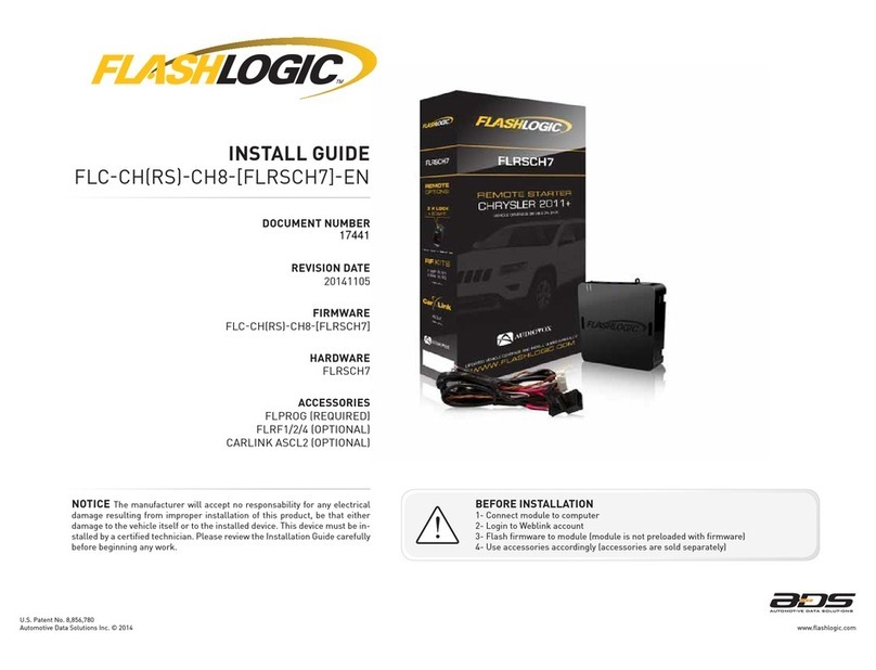
FlashLogic FLRSCH7 User manual

FlashLogic

FlashLogic FLRSCH7 User manual

FlashLogic FLC-CH(RS)-CH5-[FLRSCH5]-EN User manual
FlashLogic

FlashLogic FLC-CH(RS)-CH5-[FLRSCH5]-EN User manual

FlashLogic FLRSGM10 User manual

FlashLogic

FlashLogic FLRSGM10 User manual
FlashLogic FLC-AL-CH4 User manual

FlashLogic

FlashLogic FLC-AL-CH4 User manual
FlashLogic FLC-AL-GM2-EN User manual

FlashLogic

FlashLogic FLC-AL-GM2-EN User manual
FlashLogic FLRSGM7 User manual

FlashLogic

FlashLogic FLRSGM7 User manual

FlashLogic FLRSGM7 User manual

FlashLogic

FlashLogic FLRSGM7 User manual
FlashLogic FLC-DL-GM2 User manual

FlashLogic

FlashLogic FLC-DL-GM2 User manual
FlashLogic FLC-AL(DL)-CH4-EN User manual
FlashLogic

FlashLogic FLC-AL(DL)-CH4-EN User manual

FlashLogic DIR-CH8 User manual

FlashLogic

FlashLogic DIR-CH8 User manual

FlashLogic FLRSCH5 User manual

FlashLogic

FlashLogic FLRSCH5 User manual

Popular Remote Starter manuals by other brands
FamilyTool FMT002JST instruction manual

FamilyTool

FamilyTool FMT002JST instruction manual

PowerJump LMD-021 user manual

PowerJump

PowerJump LMD-021 user manual

AstroStart 803U user manual

AstroStart

AstroStart 803U user manual

Durite 0-649-20 Leaflet

Durite

Durite 0-649-20 Leaflet

Linear ACCESS AK-21 Installation and programming instructions

Linear

Linear ACCESS AK-21 Installation and programming instructions

Soundstream TARANTULA RS.2 installation guide

Soundstream

Soundstream TARANTULA RS.2 installation guide

Jaycar Electronics MB3752 instruction manual
Jaycar Electronics

Jaycar Electronics MB3752 instruction manual

Ultra Start 72 Series owner's manual

Ultra Start

Ultra Start 72 Series owner's manual
ADS FLASHLOGIC FLRSVW1 Product guide

ADS

ADS FLASHLOGIC FLRSVW1 Product guide
Black Widow Security BW RAS 400 installation manual
Black Widow Security

Black Widow Security BW RAS 400 installation manual

Vector Power City DK080706 Owner's manual & warranty
Vector

Vector Power City DK080706 Owner's manual & warranty

Code Alarm CA-535 owner's manual

Code Alarm

Code Alarm CA-535 owner's manual
EINHELL EGS 3600 Directions for use

EINHELL

EINHELL EGS 3600 Directions for use
Schumacher INSTANT POWER IP-75C owner's manual
Schumacher

Schumacher INSTANT POWER IP-75C owner's manual

EINHELL BT-PS 1000 Directions for use

EINHELL

EINHELL BT-PS 1000 Directions for use
Mazda 0000-8F-H28 installation instructions
Mazda

Mazda 0000-8F-H28 installation instructions

DEI 450ESP owner's guide

DEI

DEI 450ESP owner's guide

Directed Electronics AutoCommand 28624TN Owner's installation guide
Directed Electronics

Directed Electronics AutoCommand 28624TN Owner's installation guide

manuals.online logo
manuals.online logoBrands
  • About & Mission
  • Contact us
  • Privacy Policy
  • Terms and Conditions

Copyright 2025 Manuals.Online. All Rights Reserved.

REVISION DATE
20160302
DOCUMENT NUMBER
NOTICE The manufacturer will accept no responsability for any electrical
damage resulting from improper installation of this product, be that either
damage to the vehicle itself or to the installed device. This device must be in-
stalled by a certified technician. Please review the Installation Guide carefully
before beginning any work.
BEFORE INSTALLATION
1- Connect module to computer
2- Login to Weblink account
3- Flash firmware to module (module is not preloaded with firmware)
4- Use accessories accordingly (accessories are sold separately)
U.S. Patent No. 8,856,780
INSTALL GUIDE
FLCHARSHA6PFLRSHA6EN
HARDWARE
FLRSHA6
ACCESSORIES
FLPROG REQUIRED
FLRF1/2/4 OPTIONAL
CARLINK ASCL2 OPTIONAL
FIRMWARE
FLCHARSHA6PFLRSHA6
www.flashlogic.comAutomotive Data Solutions Inc. © 2016
27448
U.S. Patent No. 8,856,780
VEHICLE LIST - 1 OF 1
MAKE
MODEL
YEAR
INSTALL TYPE
FEATURES
DATA IMMOBILIZER BYPASS
3X LOCK START/STANDALONE MOD.
ARM OEM ALARM
DISARM OEM ALARM
DOOR LOCK
DOOR UNLOCK
TRUNK/HATCH RELEASE
DOOR STATUS OUTPUT
TRUNK STATUS OUTPUT
HOOD STATUS OUTPUT*
AUTOLIGHT CTRL
TACHOMETER OUTPUT
BRAKE PEDAL STATUS
ACURA
RLX PTS AT* 14-15 1 • • • • • • • • • • • • •
HONDA
Accord PTS AT* 13-16 1 • • • • • • • • • • • • •
Accord Hybrid PTS AT* 13-16 1 • • • • • • • • • • • • •
Civic PTS AT* 14-15 2 • • • • • • • • • • • •
CR-V PTS AT* 15-16 2 • • • • • • • • • • • • •
CR-V Touring PTS AT* 15-16 1 • • • • • • • • • • • • •
Crosstour PTS AT* 13-15 1 • • • • • • • • • • • • •
NOTES
* WARNING:
1- No takeover available.
Upon opening vehicle door engine will shutdown.
2- All doors must be closed to remote start vehicle.
*Available only if vehicle is equipped with factory hood switch.
www.flashlogic.comAutomotive Data Solutions Inc. © 2016 FLCHARSHA6PFLRSHA6EN
PAGE 2 OF 18
• 20160302
DOC.: #27448
U.S. Patent No. 8,856,780
BOX CONTENTS - 1 OF 1
3
6
4
1
2
5
C
B
A
F
G
E
D
7
9
3
10
8
11
13
14
12
15
17
18
19
20
16
6
4
1
2
5
7
9
3
10
8
11
12
6
4
1
2
5
2
1
3
7
9
3
10
8
6
4
12
5
2
1
3
4
2
1
3
4
VS2VS2
VS1VS1
VS4VS4
VS3VS3
MS1MS1
MS2MS2
BOX CONTENTS
T-HARNESS 1
AFTERMARKET HOOD SWITCH AND CABLE
WARNING STICKER
10 PIN CONNECTOR
12 PIN CONNECTOR
BLUE
PROGRAMMING
BUTTON
LED 2
LED 1
MODULE
BLACK
BLACK
BLACK
RF PORT/
WEBLINK PORT
BLACK
BLUE
TELEMATIC
PORT
WHITE
WEBLINK CABLE (required accessory sold separately)
WEBLINK CABLE
COMPUTER
USB PORT
4 PIN BLACK CABLE
MODULE
WEBLINK PORT
www.flashlogic.comAutomotive Data Solutions Inc. © 2016 FLCHARSHA6PFLRSHA6EN
PAGE 3 OF 18
• 20160302
DOC.: #27448
U.S. Patent No. 8,856,780
www.flashlogic.comAutomotive Data Solutions Inc. © 2016 FLCHARSHA6PFLRSHA6EN
PAGE 4 OF 18
• 20160302
COMPATIBLE ACCESSORIES - 1 OF 1
FLRF1/2/4 RF KIT
RF KIT (accessories sold separately)
(NC)
ANTENNA
MODULE
RF PORT
FLHRNTM
TELEMATIC KIT (accessories sold separately)
(NC)
CARLINK
MODULE
TELEMATIC PORT
10 11 12 13 14 15 16
12345678
9
FLHRNTM
TELEMATIC KIT (accessories sold separately)
MODULE
TELEMATIC PORT
CAR CONNECTIONPN 4120260 OBDII CONNECTOR
VEHICLE
OBDII PORT
(NC)
DOC.: #27448
U.S. Patent No. 8,856,780
TYPE 1 - WIRE CHART - 1 OF 1
MAKE
MODEL
YEAR
WIRE
DESCRIPTION
CONNECTOR
NAME
CONNECTOR
COLOR
CONNECTOR
TYPE
POSITION
WIRE
COLOR
POLARITY
MODULE
LOCATION
COMPONENT
LOCATOR
ACURA
RLX
PTS AT 14-15
Parking Light ~ Blue 12 pin 08 Pink (-) Parking light switch (left of steering column) ~
Horn ~ ~ ~ A10 Orange (-) Steering wheel clock spring connector ~
PTS Harness ~ ~ ~ ~ ~ ~ Smart PCU, under dash, left of steering column ~
Ignition Harness ~ ~ ~ ~ ~ ~ Smart PCU, under dash, left of steering column ~
HONDA
Accord
PTS AT 13-16
Parking Light ~ Blue 12 pin 08 Gray (-) Parking light switch (left of steering column) ~
Horn ~ ~ ~ A2 LtBlue (-) Steering wheel clock spring connector ~
PTS Harness ~ ~ ~ ~ ~ ~ Smart PCU, under dash, left of steering column ~
Ignition Harness ~ ~ ~ ~ ~ ~ Smart PCU, under dash, left of steering column ~
Accord Hybrid
PTS AT 13-16
Parking Light ~ Blue 12 pin 08 Gray (-) Parking light switch (left of steering column) ~
Horn ~ ~ ~ A2 LtBlue (-) Steering wheel clock spring connector ~
PTS Harness ~ ~ ~ ~ ~ ~ Smart PCU, under dash, left of steering column ~
Ignition Harness ~ ~ ~ ~ ~ ~ Smart PCU, under dash, left of steering column ~
Crosstour
PTS AT 13-15
Parking Light ~ Blue 12 pin 08 Gray (-) Parking light switch (left of steering column) ~
Horn ~ ~ ~ A2 LtBlue (-) Steering wheel clock spring connector ~
PTS Harness ~ ~ ~ ~ ~ ~ Smart PCU, under dash, left of steering column ~
Ignition Harness ~ ~ ~ ~ ~ ~ Smart PCU, under dash, left of steering column ~
CR-V Touring
PTS AT 15-16
Parking Light ~ Gray 12 pin 08 Blue (-) Parking light switch (left of steering column) ~
Horn ~ ~ ~ ~ ~ ~ ~ ~
PTS Harness ~ ~ ~ ~ ~ ~ Smart PCU, behind glove box ~
Ignition Harness ~ ~ ~ ~ ~ ~ Smart PCU, behind glove box ~
www.flashlogic.comAutomotive Data Solutions Inc. © 2016 FLCHARSHA6PFLRSHA6EN
PAGE 5 OF 18
• 20160302
DOC.: #27448
U.S. Patent No. 8,856,780
A
B
7
9
3
10
8
11
13
14
12
15
17
18
19
20
16
6
4
1
2
5
3
6
4
1
2
5
C
7
9
3
10
8
11
12
6
4
1
2
5
D
7
9
3
10
8
6
4
1
2
5
C
B
A
F
G
E
D
MS1MS1
MS2MS2
123456
789 10 11 12
VS2VS2
VS1VS1
VS4VS4
VS3VS3
OPTIONAL
PARKING LIGHT SWITCH (LEFT OF STEERING WHEEL)
HORN (-)
TYPE 1 - WIRING DIAGRAM - 1 OF 1
MODULE
04 GRAY/WHITE - HOOD STATUS (-) INPUT
AFTERMARKET HOOD SWITCH (-)
TELEMATIC PORT
RF PORT/WEBLINK PORT
PARKING LIGHT (-) - 08
28 PIN PTS CONNECTOR
24 PIN IGNITION CONNECTOR
24 PIN IGNITION HARNESS
28 PIN PTS HARNESS
SMART PCU (SEE WIRE CHART FOR LOCATION)
WITHOUT OEM HOOD SWITCH:
INSTALL AND CONNECT TO
AFTERMARKET HOOD SWITCH
RELAY
01 BROWN/BLACK - PARKING LIGHT (-) OUTPUT
02 GRAY (NC)
03 EMPTY
04 EMPTY
05 EMPTY
07 EMPTY
09 EMPTY
10 EMPTY
06 PURPLE/GREEN (NC)
08 BLUE/GREEN (NC)
11 GRAY/GREEN - HORN (-) OUTPUT
12 DKGREEN/GREEN (NC)
www.flashlogic.comAutomotive Data Solutions Inc. © 2016 FLCHARSHA6PFLRSHA6EN
PAGE 6 OF 18
• 20160302
DOC.: #27448
U.S. Patent No. 8,856,780
TYPE 2 - WIRE CHART - 1 OF 1
MAKE
MODEL
YEAR
WIRE
DESCRIPTION
CONNECTOR
NAME
CONNECTOR
COLOR
CONNECTOR
TYPE
POSITION
WIRE
COLOR
POLARITY
MODULE
LOCATION
COMPONENT
LOCATOR
HONDA
Civic
PTS AT 14-15
Parking Light ~ Gray 12 pin 08 Gray (-) Parking light switch (left of steering column) ~
Lock ~ ~ ~ ~ Blue (-) Driver door harness ~
Unlock ~ ~ ~ ~ Gray (-) Driver door harness ~
Horn ~ ~ ~ A2 Orange (-) Steering wheel clock spring connector ~
PTS Harness ~ ~ ~ ~ ~ ~ Smart PCU, under dash, above and right of steering column* ~
Ignition Harness ~ ~ ~ ~ ~ ~ Smart PCU, under dash, above and right of steering column* ~
CR-V
PTS AT 15-16
Parking Light ~ Gray 12 pin 08 Blue (-) Parking light switch (left of steering column) ~
Lock ~ ~ ~ ~ LtGreen (-) Passenger door harness ~
Unlock ~ ~ ~ ~ Tan (-) Passenger door harness ~
Horn ~ ~ ~ ~ ~ ~ ~ ~
PTS Harness ~ ~ ~ ~ ~ ~ Smart PCU, behind glove box ~
Ignition Harness ~ ~ ~ ~ ~ ~ Smart PCU, behind glove box ~
* If vehicle is equipped with an OEM amplifi er, it has to be removed to access Smart PCU.
www.flashlogic.comAutomotive Data Solutions Inc. © 2016 FLCHARSHA6PFLRSHA6EN
PAGE 7 OF 18
• 20160302
DOC.: #27448
U.S. Patent No. 8,856,780
VS2VS2
VS1VS1
VS4VS4
VS3VS3
A
B
7
9
3
10
8
11
13
14
12
15
17
18
19
20
16
6
4
1
2
5
3
6
4
1
2
5
C
7
9
3
10
8
11
12
6
4
1
2
5
D
7
9
3
10
8
6
4
1
2
5
C
B
A
F
G
E
D
MS1MS1
MS2MS2
123456
789 10 11 12
OPTIONAL
28 PIN PTS CONNECTOR
24 PIN IGNITION CONNECTOR
24 PIN IGNITION HARNESS
28 PIN PTS HARNESS
PARKING LIGHT SWITCH (LEFT OF STEERING COLUMN)
HORN (-)
TYPE 2 - WIRING DIAGRAM - 1 OF 1
MODULE
04 GRAY/WHITE - HOOD STATUS (-) INPUT
WITHOUT OEM HOOD SWITCH:
INSTALL AND CONNECT TO
AFTERMARKET HOOD SWITCH
SEE WIRE CHART
AFTERMARKET HOOD SWITCH (-)
TELEMATIC PORT
RF PORT/WEBLINK PORT
PARKING LIGHT (-) - 08
LOCK (-)
UNLOCK (-)
RELAY
03 GRAY/BLACK (NC)
01 BROWN/BLACK - PARKING LIGHT (-) OUTPUT
02 GRAY (NC)
03 EMPTY
04 EMPTY
05 EMPTY
07 EMPTY
09 EMPTY
10 EMPTY
06 PURPLE/GREEN - LOCK (-) OUTPUT
08 BLUE/GREEN (NC)
11 GRAY/GREEN - HORN (-) OUTPUT
12 DKGREEN/GREEN - UNLOCK (-) OUTPUT
SMART PCU (SEE WIRE CHART FOR LOCATION)
www.flashlogic.comAutomotive Data Solutions Inc. © 2016 FLCHARSHA6PFLRSHA6EN
PAGE 8 OF 18
• 20160302
DOC.: #27448
U.S. Patent No. 8,856,780
01
ENGINE
START
STOP
STOP ACC ON START
ON
02
03
ENGINE
START
STOP
STOP ACC ON START
STOP
04
05
06
07
ENGINE
START
STOP
STOP ACC ON START
ON
08
09
ENGINE
START
STOP
STOP ACC ON START
STOP
10
>>
11
MODULE PROGRAMMING PROCEDURE (PTS) - 1 OF 1
Push start button once [1x] to ON position.
Wait, LED 1 will flash GREEN rapidly.
Push start button once [1x] to OFF position.
WARNING: Disconnect power last. Disconnect
module from vehicle.
Connect module to computer and proceed
with extended programming.
Connect power first. Connect module to
vehicle.
Push start button once [1x] to ON position.
Wait, LED 1 will turn solid GREEN for 2
seconds.
Push start button once [1x] to OFF position.
Press UNLOCK on the OEM remote.
If the vehicle is equipped with a power liftgate:
Open and close the power liftgate with the
OEM keyfob.
Module Programming Procedure completed.
www.flashlogic.comAutomotive Data Solutions Inc. © 2016 FLCHARSHA6PFLRSHA6EN
PAGE 9 OF 18
• 20160302
DOC.: #27448
U.S. Patent No. 8,856,780
>>
01
02
ENGINE
START
STOP
OFF ACC ON START
ON
03
04
ENGINE
START
STOP
OFF ACC ON STARTOFF
05
>>
VALET MODE PROGRAMMING PROCEDURE - 1 OF 1
NOTE: In Valet Mode, the Remote starter is not
functional. Keyless entry, Lock and Unlock will
remain functional. See RF kit user manual for
alternate valet mode programming.
Time restriction. Complete next step within 7
seconds.
Cycle ignition ON five times [5x OFF/ON]
rapidly.
Wait, LED 1 will turn solid RED for 2 seconds.
Set ignition to OFF position.
Valet Mode Programming Procedure
completed.
To exit valet mode: repeat steps 1 to 5.
www.flashlogic.comAutomotive Data Solutions Inc. © 2016 FLCHARSHA6PFLRSHA6EN
PAGE 10 OF 18
• 20160302
DOC.: #27448