FLETCHER Alfamacchine T-300 User manual

EN INSTRUCTIONS MANUAL
PLEASE RETAIN FOR FUTURE REFERENCE
Name DOUBLE MITRE SAW FOR “V” CUTTING
Function 45° CUTTING OF MOULDINGS MADE FROM WOOD, ENGINEERED WOOD AND SIMILAR, HARD
PLASTIC AND LIGHTWEIGHT ALLOYS
Model / Type T300/T350/T400
Serial number
Year of construction
Manual Revision 01

2TRANSLATION OF THE ORIGINAL INSTRUCTIONS (Keep for future reference)
Document Code Rev. Date saved Date printed
T300 - T350 - T400 ISTRUZIONI 01 14/07/2016 14/07/2016
EN
Alfamacchine S.r.l.
Via Curie M. e P., 3
47122 Forlì - Italy
EC DECLARATION OF CONFORMITY
The Manufacturer Alfamacchine S.r.l.
&XULH0DULHH3LHUUH
47122 Forlì - Italy
Tel. +39. 0543.783301
that the machine:
HEREBY DECLARES,
Model: T300-T350-T400
Type: PNEUMATIC
Serial number:
- Machinery Directive 2006/42/EC
- Electromagnetic Compatibility (EMC) Directive 2014/30/EU
REFERENCE TO HARMONIZED STANDARDS APPLIED:
EN ISO 12100:2010; EN 60204-1:2006; UNI EN 1870-16:2012
NOTIFIED BODY no. 0476
KIWA CERMET ITALIA S.p.a.
40057 - GRANAROLO DELL’EMILIA (BO)
And authorizes
Alfamacchine S.r.l.
&XULH0DULHH3LHUUH
47122 Forlì (FC)
TO COMPILE THE TECHNICAL FILE ON ITS BEHALF
___________________________________ _______________________________
Date The Manufacturer

1
TRANSLATION OF THE ORIGINAL INSTRUCTIONS (Keep for future reference)
Document Code Rev. Date saved Date printed
T300 - T350 - T400 ISTRUZIONI 01 14/07/2016 14/07/2016 EN
TRANSLATION OF THE ORIGINAL INSTRUCTIONS
INDEX
EN
1. INTRODUCTION TO USE......................................................................................................................................................... 2
1.1. HOW TO CONSULT THIS MANUAL AND THE SYMBOLS ADOPTED ....................................................................... 2
1.3. TYPE OF USE AND CONTRAINDICATIONS............................................................................................................... 5
1.4. TECHNICAL CHARACTERISTICS............................................................................................................................... 7
1.5. PRODUCTS PROCESSED - HANDLED OR GENERATED ........................................................................................ 7
1.6. EMISSION OF AIRBORNE NOISE............................................................................................................................... 8
1.7. SAFETY INSTRUCTIONS ............................................................................................................................................ 8
1.7.1. RESIDUAL RISKS ........................................................................................................................................................ 8
1.7.2. DANGERS .................................................................................................................................................................... 9
1.8. DESCRIPTION OF SAFETY FUNCTIONS................................................................................................................. 10
1.9. MACHINE DESCRIPTION.......................................................................................................................................... 12
1.10. MAIN MACHINE COMPONENTS................................................................................................................................ 12
2. INSTALLATION ....................................................................................................................................................................... 16
2.1. STORING.................................................................................................................................................................... 16
2.2. CHECKS ON RECEPTION......................................................................................................................................... 16
................................................................................................................... 17
2.4 LIFTING AND HANDLING .......................................................................................................................................... 17
.................................................................................................................................. 19
3. PRELIMINARY PREPARATION AND ADJUSTMENT PROCEDURES ................................................................................. 20
3.1. POSITIONING............................................................................................................................................................. 20
3.2. SECURING THE MACHINE TO THE FLOOR ............................................................................................................ 20
4. INITIAL START-UP AND USE OF THE MACHINE................................................................................................................. 24
4.1. WORKSTATIONS AND OPERATORS' TASKS........................................................................................................... 24
.............................................................................................................. 24
4.3. START-UP................................................................................................................................................................... 25
5. MAINTENANCE, TROUBLESHOOTING AND CLEANING ................................................................................................... 32
5.1. MAINTENANCE TECHNICIAN REQUIREMENTS ..................................................................................................... 32
5.2. WORK STATIONS AND MAINTENANCE TECHNICIAN DUTIES.............................................................................. 32
5.3. MAINTENANCE PRESCRIPTIONS............................................................................................................................ 32
5.4. GENERAL WARNINGS .............................................................................................................................................. 32
5.6. ROUTINE MAINTENANCE......................................................................................................................................... 33
5.6.1. TASKS THAT CAN BE PERFORMED BY THE OPERATOR ..................................................................................... 34
5.6.2. TASKS THAT CAN BE PERFORMED ONLY BY MAINTENANCE TECHNICIANS ................................................... 35
Blade replacement ...................................................................................................................................................... 36
Cutting angle adjustment ............................................................................................................................................ 37
Blade positioning......................................................................................................................................................... 37
Checking the vertical angle of the blades ................................................................................................................... 37
............................................................................................... 38
Condensate drainage from tanks ............................................................................................................................... 40
Check the vertical stoppers for wear........................................................................................................................... 41
Checking the horizontal stopper (optional) for wear.................................................................................................... 41
Checking the internal stopper (optional) for wear ....................................................................................................... 41
........................................................................................................................... 42
Check the oil level in the pneumatic unit..................................................................................................................... 42
Lubricator adjustment.................................................................................................................................................. 42
5.6.3 CLEANING.................................................................................................................................................................. 43
Stem lubrication (by the maintenance technican) ....................................................................................................... 46
Grease nipple lubrication (by the maintenance technician) ........................................................................................ 46
6. TROUBLESHOOTING AND RELEASE OF MOVING PARTS ............................................................................................... 47
7. REINSTALLATION AND REUSE ............................................................................................................................................ 48
8. INSTRUCTIONS FOR EMERGENCIES.................................................................................................................................. 49
9. SCRAPPING AND DISPOSAL................................................................................................................................................ 49
9.1. SCRAPPING............................................................................................................................................................... 49
9.2. DISPOSAL .................................................................................................................................................................. 50
PNEUMATIC DIAGRAM ................................................................................................................................................................... 51
ELECTRICAL DIAGRAM.................................................................................................................................................................. 52
ELECTRICAL SYSTEM ON BOARD THE MITRE SAW MACHINE................................................................................................ 53

2TRANSLATION OF THE ORIGINAL INSTRUCTIONS (Keep for future reference)
Document Code Rev. Date saved Date printed
T300 - T350 - T400 ISTRUZIONI 01 14/07/2016 14/07/2016
EN
DANGER - WARNING
BEFORE USING THE MACHINE PLEASE READ THIS MANUAL CAREFULLY SO THAT YOU BECOME FAMILIAR
WITH THE MACHINE, ITS ENVISAGED USE AND ANY RISKS ASSOCIATED WITH IT.
to get best machine performance in maximum safety while performing the operations described therein.
DANGER - WARNING
USE THE MACHINE SOLELY AND EXCLUSIVELY FOR THE USES INDICATED AND IN ACCORDANCE WITH THE
RECOMMENDATIONS PROVIDED IN THIS MANUAL. NEVER TAMPER WITH IT, FORCE IT OR USE IT IN ANY
INAPPROPRIATE MANNER.
1. INTRODUCTION TO USE
1.1. HOW TO CONSULT THIS MANUAL AND THE SYMBOLS ADOPTED
accompanied by symbols and notes to highlight the presence of any hazards and indicate the safe use of the equipment. These
DANGER – WARNING: IMPORTANT INFORMATION CONCERNING GENERAL SAFETY.
DANGER-CAUTION: highlights situations where careful and sensible actions are essential.
NOTES: information of a technical nature.
3
TRANSLATION OF THE ORIGINAL INSTRUCTIONS (Keep for future reference)
Document Code Rev. Date saved Date printed
T300 - T350 - T400 ISTRUZIONI 01 14/07/2016 14/07/2016 EN
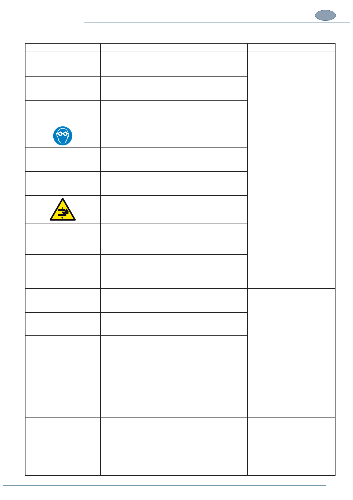
DECAL DESCRIPTION LOCATION
Wear protective goggles.
Wear protective gloves.
Wear safety footwear
Wear protective safety glasses
Wear a mask to protect the respiratory tract
Consult the instruction manual
Hand crushing hazard.
Cutting hazard
Blades dataplate
Isolate the energy source
Working pressure
Horizontal clamp command pressure adjustment
It is prohibited to perform maintenance operations on moving
parts.
This manual suits for next models
2
Table of contents


