Page2of6
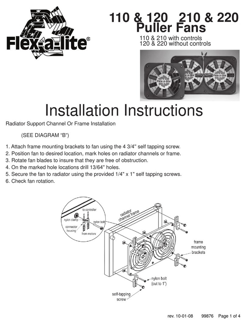
B
CMG+M+
M-
Hose clamp over sensor gasket-
DoNot Position Clamp Screw
OverGasket.
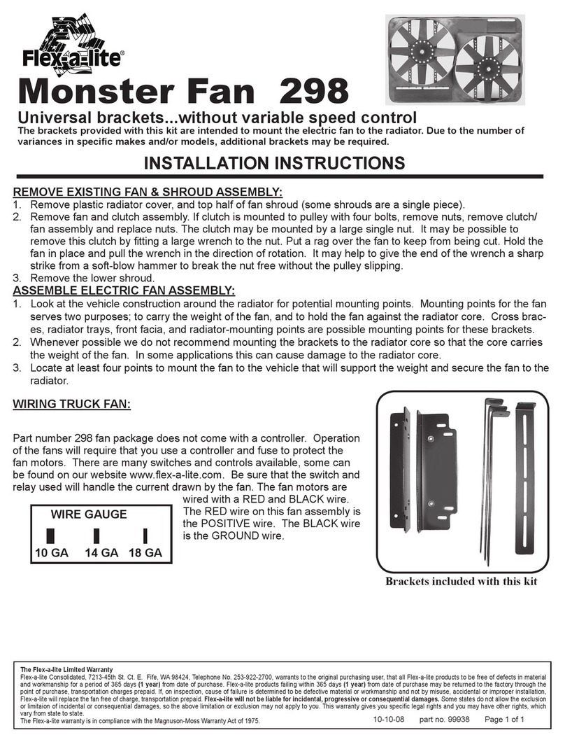
Temperature Control Sensor Bulb Installation
1. Loosen upper radiator hose at the radiator, pull the hose off
the radiator inlet pipe.
2. Insert sensor bulb, bend the sensor bulb tube around the end
of the radiator inlet pipe.
(The tube is hollow, do not kink. Use wide bends.)
3. Place the sensor gasket (rubber piece with the slit) between
the sensor bulb tube and radiator inlet pipe. Be sure the tube
lays in the slit of the rubber gasket.
4. Wrap vinyl tape around the inlet pipe and sensor tube at
least twice.
5. Replace radiator hose, tighten clamp. (Do not overtighten)
Note: You must use a screw-type hose clamp, some original
equipment clamps will leak.
Ground
12Volt Source
1 2 3
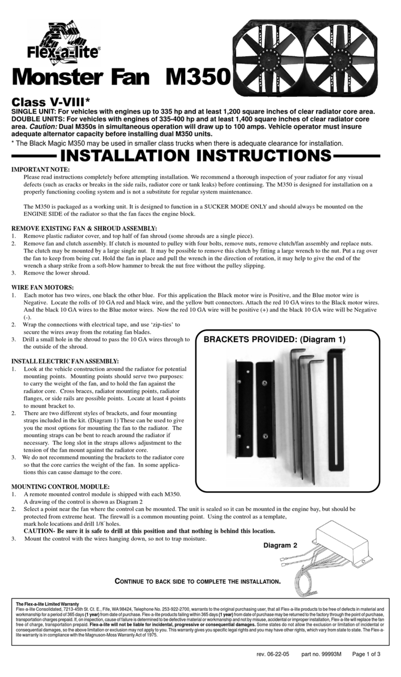
Wiring Instructions
Note: Each connection shown in this section is mandatory for operation.
1. Disconnect battery.
2. Attach black motor wire(s) to M+.
3. Attach white motor wire(s) to M-.
4. Connect the “+” terminal to a 12 volt positive (+)
power source, e.g. fuse box. Use the wire provided
in the kit.Note: To stop the fan unit from operating
when the vehicle is shut off, attach this wire to an
ignition switched 12 volt power source.
5. Connect the “B” terminal to a 12 volt positive (+)
power source, e.g. Positive side of battery, or alter-
nator. Use the wire and inline fuse provided in the
kit.
6. If you have air conditioning: Connect the “C”
terminal to the positive(+) side of the air conditioning
compressor. Splice into the A/C clutch positive wire
using the 3-way connector and wire provided in the
kit. Air Conditioning Relay (Activates fan(s) when A/C
is turned on)
7. Connect the “G” terminal to ground, i.e. chassis,
negative (-) side of the battery. Use the wire
provided in the kit.
ADJUSTING THE TEMPERATURE CONTROL
1. Attach the temperature control knob to the control box.
2. Turn the knob clockwise completely.
3. Idle the vehicle, observe the temperature of the vehicle. (Use the vehicles gauge)
4. When the temperature of the vehicle reaches above normal, turn the control knob counter-clockwise until
the fan turns on. From here on the fan should activate at this temperature setting. Adjust as necessary
according to your vehicle needs.
12Volt Positive Source
Fuse
Control Box
Temp.
SensingBulb
Control
Box
Bend capillary tube as shown.
Lay cap tube into sensor
gasket groove & wrap with
vinyl tape.
Radiator Top Tank
Whitemotor(s)
wire(s)
BlackMotor(s)
wire(s)
Capillary Tube
Do not bend less than
1/4" radius.
Wiring Instructions For Accessories
Note: Connection shown in this section is optional and is not crucial for standard operation
Manual Switch (Allows manual activation of the fan(s)
1. Connect the “M” terminal to terminal 1 of the switch. Attach separate wire to terminal 2, attach
other end of the same wire to a 12 volt positive source. To illuminate switch, connect a ground to
terminal 3.
Note: (Instructions based on Flex-a-lite manual switch, part number 31148. Manual switch not included)
Control Box Terminals
Mandatory Connections
M+ Black motor wire(s)
M- White motor wire(s)
+ 12 volt positive source
G Ground
B 12 volt positive source
C Air conditioning relay
Optional Connection
M Manual switch
The Flex-a-lite Limited Warranty
Flex-a-lite Corporation, 7213-45th Street Court East, Fife, Washington 98424, Telephone No. 253/922-2700, warrants to the original purchaser user,
all Flex-a-lite products to be free of defects in material and workmanship for a period of 365 days (1 year) from date of purchase. Flex-a-lite products
failing within 365 days (1 year) from date of purchase, may be returned to the factory through the point of purchase, transportation charges prepaid.
If, on inspection, cause of failure is determined to be defective material or workmanship and not by misuse, accident, or improper installation, Flex-
a-lite will replace the fan free of charge, transportation prepaid. Flex-a-lite will not be liable for incidental, progressive, or consequential
damages. Some states do not allow the exclusion or limitation of incidental or consequential damages, so the above limitation or exclusion may not
apply to you. This warranty gives you specific legal rights and you may also have other rights, which vary from state to state.
12VoltSource
*WARNING: If not using Flex-a-lite’s illuminated switch
(PN #31148) you must disconnect the switch ground.
Ground
(Illuminate switch connection
forFlex-a-litePart #31148)
A/C positive (+)
wire from clutch
3-way
connector
