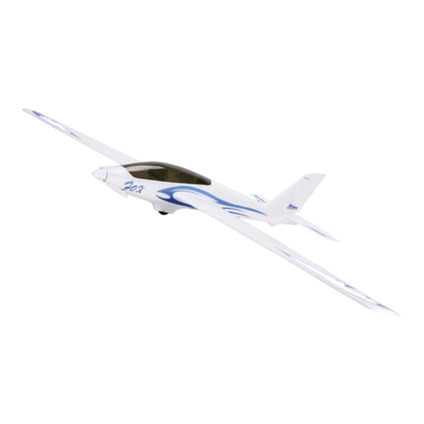
Flex innovations RV-8 60E G2 User manual


Other manuals for RV-8 60E G2
1
Table of contents
Other Flex innovations Toy manuals

Flex innovations
Flex innovations RV-8 10 Super PNP User manual

Flex innovations
Flex innovations MAMBA 120 User manual

Flex innovations
Flex innovations QQ Cap 232EX User manual

Flex innovations
Flex innovations FeatherLite RV-8 70cc FLS User manual

Flex innovations
Flex innovations FV-31 Cypher User manual

Flex innovations
Flex innovations SUPER PNP User manual

Flex innovations
Flex innovations Cessna 170 60E G2 User manual

Flex innovations
Flex innovations MAMBA 10 User manual
Flex innovations
Flex innovations Twin Otter 80E User manual

Flex innovations
Flex innovations FV-31 Cypher Installation and operating instructions

Flex innovations
Flex innovations Super PNP F-100D Super Sabre User manual

Flex innovations
Flex innovations Pirana User manual

Flex innovations
Flex innovations Mamba 60E+ Super PNP User manual

Flex innovations
Flex innovations FlexJet Pro 90 mm User manual
Flex innovations
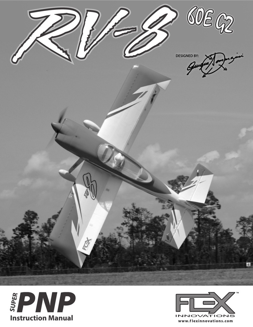
Flex innovations RV-8 60E G2 User manual

Flex innovations
Flex innovations 6S RawPower MAMBA 10 G2 User manual
Popular Toy manuals by other brands

Beyblade
Beyblade Spiral Blitz 2-Pack instructions

Chicco
Chicco Super Rocking Rings 63259 instructions

REVELL
REVELL Albatross D III Assembly manual
MGA
MGA NUM NOMS Snackables Birthday Cake Slime Kit quick guide

American Flyer
American Flyer GP 7/9 owner's manual
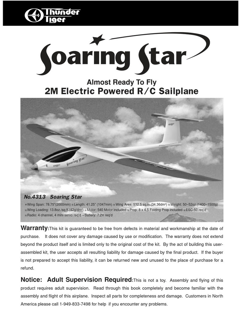
THUNDER TIGER
THUNDER TIGER Soaring Star Assembly instruction
