FlexArm B-19 User manual

1
I N S T A L L A T I O N & O P E R A T I ON S
MA N U A L
F l e x A r m
B - 1 9
Distributed by Ergonomic Partners
www.ErgonomicPartners.com
Tel: (314) 884-8884
Book Part No 360740
12/2014
REV.000

2
Table of Contents:
TOPIC: Page:
3
Safe Operation: READ THIS FIRST
Warranty
4
Specifications
4
Installation
5-7
Operating Instructions
8
Parts Diagram
9-10
Plumbing Diagram and Air System Parts
11
Range of Motion
12
REV.000

3
SAFE OPERATION: READ THIS FIRST
READ THE ENTIRE UNIT MANUAL BEFORE OPERATING
WEAR EYE PROTECTION WHEN OPERATING THIS EQUIPMENT
DO NOT WEAR JEWELRY OR LOOSE CLOTHING WHEN OPERATING
TIE HAIR BACK BEFORE USING MACHINE
DO NOT WEAR GLOVES WHEN OPERATING THIS EQUIPMENT
DO NOT USE DAMAGED, FRAYED OR DETERIORATED AIR HOSES
OR FITTINGS
KEEP HANDS CLEAR OF PINCH POINTS ON THE UNIT WHEN
OPERATING
PERIODICALLY INSPECT FOR DAMAGE, LOOSE HARDWARE OR
ANYTHING IRREGULAR
READ THE FLEXARM WARRANTY PAGE BEFORE PERFORMING
ANY MAINTENANCE OR REPAIRS
DISCONNECT THE AIR SUPPLY AND REMOVE ANY WEIGHT
FROM THE ARM BEFORE MAKING ANY ADJUSTMENTS TO THE
ARM OR PERFORMING ANY MAINTENANCE
DO NOT ALTER OR MODIFY THE FLEXARM
IT IS IMPERATIVE THAT THE TABLE OR MOUNTING SURFACE
BE LAGGED TO THE FLOOR AND SECURE BEFORE
INSTALLING THE FLEXARM B-19.
Failure to secure the table or mount surface could result in serious
injury to the operator as well as the FlexArm.
FlexArm is not responsible for accident or injury resulting from the
misuse of this unit or for use other than originally designed and
intended.
The B-19 arm has torque and tool restrictions. See page 4 of
this manual for these restrictions.
Please contact FlexArm with any questions or concerns about
the installation of the FlexArm B-19 assembly arm at
800-837-2503.
REV.000

4
FlexArm
Limited Warranty
A new FlexArm has a 3-year limited warranty on parts and labor. This warranty
does not apply to a FlexArm determined to have been misused or abused,
improperly maintained, or having defects attributed to the use of non-genuine
repair parts.
Air cylinders have a one-year limited warranty from the date of purchase. When
replacing a cylinder, make sure not to scratch, mar, or nick the shaft or tube on
either the old cylinder being replaced or the new cylinder being installed. All
warranty cylinders must be returned to FlexArm for evaluation. The warranty is
void if the cylinder to be evaluated shows signs of scratches or nicks on the
cylinder shaft or tube. Damaged cylinders cannot be returned to the manufacturer
for warranty claims.
This warranty is void if it has been determined that the FlexArm was misused,
abused or improperly maintained.
FlexArm is not responsible for a customer’s air quality. The unit is supplied with
an auto-drain air filter but the responsibility for clean, dry air falls upon the
individual shop.
Once the original warranty expires, Arms carry a limited 60-day warranty
from the date of the repair.
For technical assistance or questions concerning the proper care and maintenance
of the FlexArm unit, please contact FlexArm at 800-837-2503.
Rev. 7/01/14
TORQUE AND WEIGHT LIMITATIONS
Model
Number
Max Motor Torque
Working Range
Max Tool Weight
Ft Lbs
Nm
Inches
Cm
Lbs
Kg
B-19
100
137
1-42
3-107
35
15.9
***Exceeding the weight and torque limitations will void the factory warranty***
REV.000

5
0.406
4 PLACES
EQUALLY
SPACED
4.50
BOLT CIRCLE
5.50
BASE MOUNT
3/8" DIAMETER
MOUNTING BOLTS
(4 REQUIRED)
FLAT MOUNTING SURFACE
ANGLE MOUNT BOLT
WASHER
ANGLE MOUNT
INSTALLATION
1)Drill and tap (4) 3/8" bolt holes on a flat, smooth table or work bench.
(see Base Mount diagram below)
Base Mount pattern
2 ) Secure the Base Mount to the worktable. Slide the Angle Mount onto the shaf t of
the Base Mount and secure the angle wi th the washer & cap screw
before inserting
the FlexArm!
The angle mount may not slide easily through both bearing sets , so
make sure the angle is straight up and down and tap lightly with a rubber mallet if
necessary.
(se e A ngle M ount as semb ly dia gr am bel ow )
REV.000

6
INSTALLATION
3)Insert the rear pin into the upper bore and bearing of the an gle mount. The rear
pin may not slide easily through both be aring sets . Use the cap sc rew to help pull
the unit completely through the bottom be aring.
It may require two people to support t he arm and gui de the rear pin into the
bearing sets.
4) Ins tall the levers at either end or the angle. These are for adjusting the
amount of force needed to move the angle and rear pin.
Tighteni ng the lever wi ll increase the force needed to move the joint and
loos ening the lever will decr ease the amount of for ce needed.
5) Check all airline connections to ensure that no hoses have come loose from the
press-to-release fittings. Hoses m ust be complete ly pushed into the fitti ngs to
lock unde r pressure. Check the connec tion by gently pulling on the hose.
6) Ins tall a ¼”NPT fi tting into the left (input) port of the filter assembly. It is
recomme nded that a 3/8"ID incoming air line be used to get maximum air flow. The
pneumati c system on the FlexArm will require a minimum of 90 -120 psi input to
perform the maximum balancing operations.
7) The air filter is equipped with an auto drain and will autom atically remove
moisture from the bowl.
REV.000

7
INSTALLATION WITH PEDESTAL MOUNT
1) Secure the pedestal to the floor with (8) 1/2" dia meter wedge anchor bolts drilled
a minimum of 3-3/4" into the concrete.
2) Secure the base of the unit to the pedestal with (4) 3/8" bolts .
REV.000

8
OPERATING INSTRUCTIONS
1) Mount tool in the V -block assembly on the e nd of the B -19 assembly arm.
2) Chec k the air regul ator on the rear pin of the B -19. Make sure the knob is
turned comple tely counter -clockwise. Do not remove the knob. Ensure it is
tu rned a s f ar c ou nter -cl oc kwi se as p ossi ble wi thout r emov ing i t. F AILU RE TO
DO SO COULD RESULT IN INJURY IF AIR IS CONNECTED PRIOR TO THIS STEP!
3) Connect air supply to the air filter on the rear pin of the B -19 arm.
(A ir su pply sh ould be at 90 - 12 0 ps i.)
4) Adjust air regulator clockw ise until arm counterbalances the weight of the tool .
5) Always wear safety glasses and use proper safety precautions when
operating this unit.
IT IS IMPERATIVE THAT THE TABLE OR MOUNTING SURFACE BE LAGGED TO THE
FLOOR AND SECURE BEFORE USING THE FLEXARM B-19.
FlexArm is not responsible for accident or injury resulting from the misuse of
this machine or for use other than originally designed and intended.
REV.000

9
B-19 PARTS DIAGRAM: LOWER ASSEMBLY
Item
No
:
Part No:
Description:
QTY
Used
1
360701
BASE
1
2
360703
LOWER ANGLE ASSEMBLY
1
3
360706
UPPER ANGLE ASSEMBLY
1
4
360716
BEARING
4
5
360717
SPACER
2
6
360702
ANGLE WASHER
2
7
360315
LEVER
2
8
360707
REAR PIN ASSEMBLY
1
9
0375M
SOCKET HEAD CAP SCREW 3/8-16x1
2
10
360737
HEX HEAD BOLT 1/2-13x1-1/4 GRADE 5
2
11
360738
HEX NUT 1/2-13
2
REV.000
10
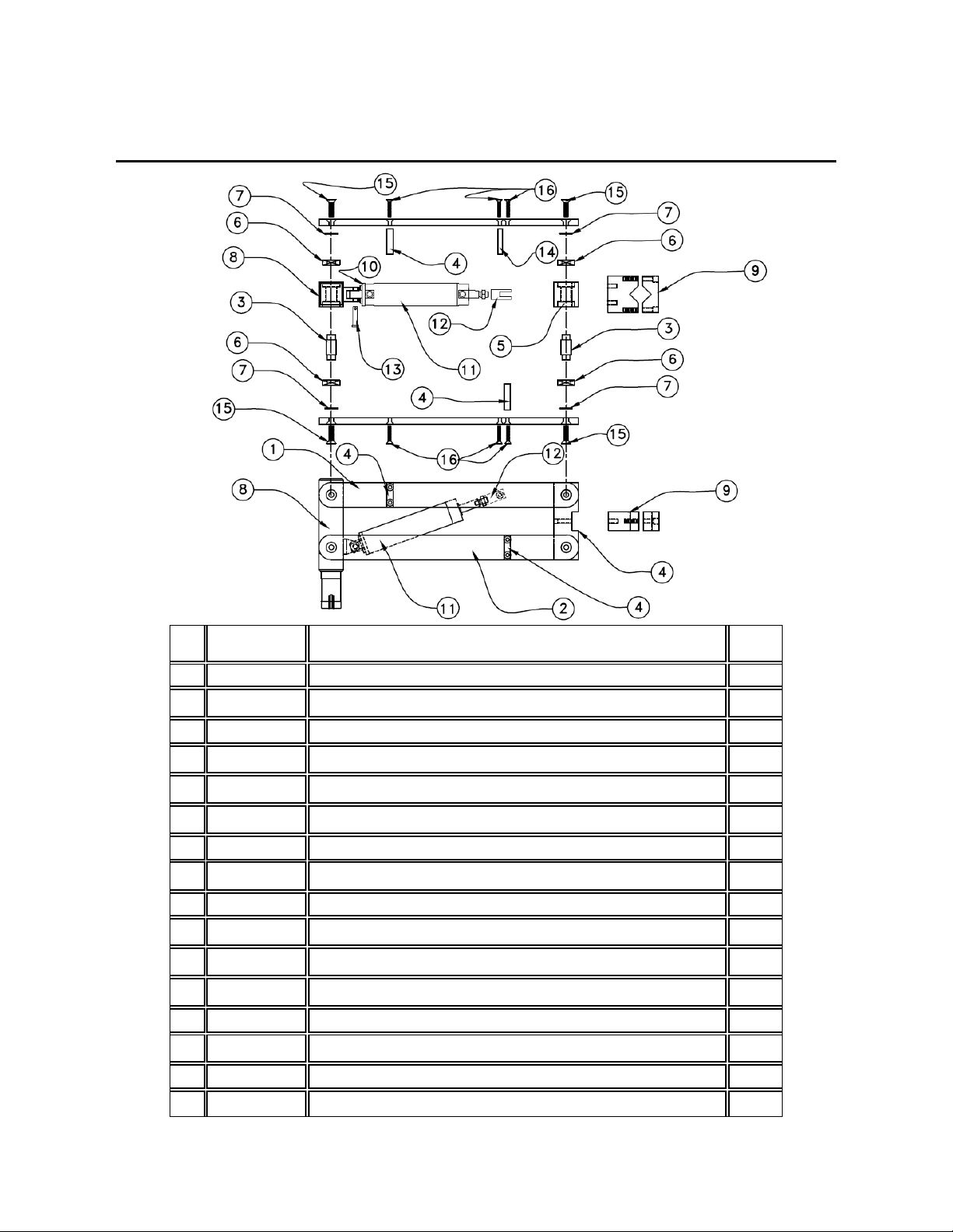
B-19 PARTS DIAGRAM: UPPER ASSEMBLY
Item
No
:
Part No:
Description:
QTY
Used
1
360710
ARM UPPER
2
2
360711
ARM LOWER
2
3
360712
ARM PIN
4
4
360713
ARM SPACER BLOCK
2
5
360714
FRONT BLOCK
1
6
360715
ARM BEARING
8
7
360719
ARM SHIM
8
8
360707
REAR PIN ASSEMBLY
1
9
360739
V—BLOCK ASSEMBLY
1
10
360722
AIR CYLINDER SINGLE MOUNTING CLEVIS
1
11
360723
AIR CYLINDER
1
12
360724
DOUBLE ROD CLEVIS
1
13
360728
PIN CYLINDER BASE
1
14
360729
PIN CYLINDER ROD
1
15
360720
SOCKET DRIVE FLAT HEAD SCREW 3/8-16x1-1/4
8
16
360721
SOCKET DRIVE FLAT HEAD SCREW 1/4-20x1-1/4
10
REV.000

11
360727 PRESSURE GAUGE
360062 FILTER
PLUMBING DIAGRAM AND
AIR SYSTEM PARTS
MUFFLER
REV.000

REV.000
Distributed by Ergonomic Partners
www.ErgonomicPartners.com
Tel: (314) 884-8884
12
FLEXARM B-19: RANGE OF MOTION
Table of contents
Popular Power Tools Accessories manuals by other brands

Clarke
Clarke CAT150 FITTING & MAINTENANCE

Dremel
Dremel 1453 Original instructions

Multitool
Multitool MT482 installation instructions

Hilti
Hilti TE DRS-4-A operating instructions

Scheppach
Scheppach 55 Translation from the original instruction manual

Wolfcraft
Wolfcraft 3001000 Translation of the original operating instructions


Cembre
Cembre CS-SD Operation and maintenance manual

DeWalt
DeWalt D512382 Assembly instructions

Big Daishowa
Big Daishowa BASE MASTER MICRO Operation manual

Stihl
Stihl DuroCut 20-2 manual

Sherline Products
Sherline Products 1074 quick start guide

Baileigh Industrial
Baileigh Industrial DDT-3519 Operator's manual