FlexiForce GSM-02 User manual

FLEXIFORCE GSM-02 MANUAL
UK -
FLEXIFORCE GSM-02
V2.3 EU

14
Qu ck start
The FLEXIFORCE GSM-02 works with contract as well as prepaid Sim cards. When using a
prepaid card, notice that some providers let the call credit expire after a certain time. Some
prepaid cards have to be upgraded once a year.
Be sure the card s act vated by your prov der before you nsert the card n the
GSM-02. Also, d sable the PINcode and the vo cema l, than the GSM-02 s
mmed ately ready for use.
After connecting the voltage with the GSM-02 wait till the green LED is permanently on. The
GSM-02 is gonna subscribe itself at the provider after connecting with the voltage. (It takes
1 or 2 minutes).
WHEN THE GREEN LED IS PERMANENTLY ON, THE UNIT IS ACTIVATED. THERE CAN
BE SWITCHED OR THERE CAN BE MADE A CONNECTION WITH THE SOFTWARE.
A green LED that is permanently on indicates that the GSM-02 is ready for use. You can
programm the GSM-02 by following commands.
When the green LED has a interrupt sequence, the installed Sim card is not working or there
is no contact with the provider of the Sim card.
The red LED should have a slow interrupt sequence, this indicates that the unit is completely
activated.
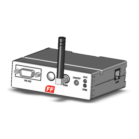
connectors for power supply, nterface and antennas:
1. On/Off push button (Not in use with the GSM-02).
2. SMA connector (female) for GSM antenna.
3. Led's GSM and Unit.
4. 9-pole (female) SUB-D plug for RS-232 serial interface.
5. Option, Not in use.
6. 24-pole GPIO 3mm Micro Mate-N-LOK connector for cable.
7. 4-pole 3mm Micro Mate-N-LOK connector for power supply.
8. 6-pole RJ11 plug (Not in use with the GSM-02)
9. SIM card holder.
Key Features of the GSM-02 Term nal:
Frequency bands: Quad band: GSM 850/900/1800/1900MH
Power supply: 5-24Vdc
Operating temperature: -20°C tot +70°C
Dimensions: 98mm x 82m x 30m
Weight: 160g
RoHS, WEEE: All hardware components are fully compliant with the EU RoHS
and WEEE Directives

15
5 4 3
2 1
7 6 Front view
Side A view
8
Side B view
9
Bottom view
Engl sh
Engl sh

16
Topview
220Vac
12Vdc
Red
Black
Yellow
Green
White
Red: Input / Output power 5-24 Vdc
Black: Ground
Yellow: IGNITION (not in use)
Green: Normally open Relay
White: Normally open Relay
The power supply of the GSM-02 Terminal has to be a single voltage source of POWER 5V-
24Vdc capable of providing a peak during an active transmission. The GSM-02 Terminal is
protected from supply voltage reversal. An internal fuse ensures an electrical safety accord-
ing to EN60950. This fuse is not removable. A fast acting fuse 0.8A with melting is neces-
sary to use with the GSM-02 Terminal at a 24V power supply system for vehicles. The power
supply must be compliant with the EN60950 guidelines.
REMARK: THE POWER SUPPLY IS INTERNALY CONNECTED FROM THE 4-PINS
CONNECTOR TO THE 24-PINS CONNECTOR. IF YOU USE THE ADAPTER, YOU HAVE
TO MAKE SURE THAT THE RED AND BLACK WIRE OF THE 24-PINS CONNECTOR DO
NOT CONNECT!!
24
12
13
1
1
2
4 3
1 – Power
2 –
3 – GND
4 –
13 – Normally open Relay
14 – Normally open Relay
23 – Ground
24 – Input / Output power 5—24 Vdc
9 – Ignition (not in use)
Connect ons / techn cal data

17
Supply voltage requ rements:
The DC power supply must be connected to the POWER input:
• Input voltage range 5 - 24V DC
• Nominal voltage 12V DC
• Power Supply current rating: min. 1,2A @12V
• Power Supply ripple: max. 120mV
• Input current in idle mode: 20mA @ 12V
Red LED status Device Status
Permanently on A call is active
Fast interrupt sequence (period 0,5 sec to 1
sec) Net search / Not registered / turning off
Slow interrupt sequence (period 0,3 sec to 3
sec) Registered full service
Permanently off Device off
Green LED status Device status
Permanently on Unit Ready for calls
Fast interrupt sequence (period 0,5 sec to 1
sec) Error
Slowly interrupt sequence (between 0,3 sec to
3 sec) Unit receive a call
Permanently off Device off
Red LED d splays the network status of the term nal.
Green LED d splays the operat ng status of the network.
Weight 160g
Dimensions (max) L x W x H 98 mm x 82mm x 30mm
Temperature range -20°C to +70°C ambient temperature
Protection class IP40 Avoid exposing GSM-02 Terminal to liquid or
moisture.
Mechanical vibrations Amplitude 7.5mm at 5-200H sinus
Air humidity 5% - 85%
Class of flammability UL94 HB
Casing material PC/ABS Cycoloy 1200 HF
Mechan cal Character st cs
Internal relay:
• Maximum voltage = 30 Voltage @ max. 1 Ampere.
• The relay is normally open (NO).
Engl sh
Engl sh

18
SMS Interface Descr pt on
(L st of SMS command for GSM-02)
1.1 Password
Every SMS starts with p:password (standard 1234)
Example: P.1234A.0541122333.0544455666
The command P. the password is 1234
the command A. is add new phone number to the list, in this example: 0541122333 en
0544455666
1.2 Add new phone number
A.phone number,phone number,...
Add new phone numbers to the phone list
Example: P.1234A.0547512152.0525874525
Add 0547512152 and 0525874525 to the phone list. When more phone numbers have to
be added, than put a DOT between the phone numbers, all SMS si e can be used.
1.3 Add spec al new phone number
AS.phone number.1.from t me,to t me week days
Add one new special phone number to the special list with specific hours during the week
days.
The “from time” and the “to time” syntax is HHMM (with no spaces)
Example 1: P.1234AS.058126248.1.1130.1540.135
Phone number 058126248 will be allowed to enter from 11:30 to 15:40 on Sunday,
Tuesday and Thursday ( 1234567 weekdays starting with sunday)
Example 2: P.1234AS.058126248.1.2300.0200.24
Phone number 058126248 will be allowed to enter from 23:30 to 02:00 on Monday and
Wednesday.
AS.phone number.3.Entr es amount
Add one new special phone number to the special list with limited entries amount.
Example 1: P.1234AS.058126248.3.6
Phone number 058126248 will be allowed to enter 6 times
Example 2: P.1234AS.058126248.3.11
Phone number 058126248 will be allowed to enter 11 times
1.4 Delete phone number
D.phone number.phone number
Delete phone numbers from regular phone list.
Example: P.1234D.0542684284.0542358721
Phone number 0542684284 and 0542358721 deleted from the regular phone list, put
comma between the phone numbers, can use all SMS si e.
When more phone numbers have to be added, than put a DOT between the phone numbers,
all SMS si e can be used.
1.5 Delete spec al phone number
DS.phone number.phone number
Delete phone numbers from special phone list.
Example: P.1234DS.0542684284.0542358721
Phone number 0542684284 and 0542358721 deleted from the special phone list. When
more phone numbers have to be added, than put a DOT between the phone numbers, all
SMS si e can be used.

19
1.6 Set puls t me (advanced)
GOD.gate open delay
Set the time of the pulse when calling to the unit, Maximum 60 seconds.
Example: P.1234GOD.7
Set the gate open to 7 second delay.
1.7 Clock update
CU
Clock update, update the unit’s clock from the SMS send time.
Example: P.1234CU
1.8 New password
NP.new password
Sets new password to the GSM-02 unit (the CSD password infect also). (be careful with it,
when lost, the module have to get back to the manufacturer)
Example: P.1234NP.4321
Change the password to 4321
1.9 Enable\D sable
EN.1.0
Set the GSM-02 unit to enable or disable.
Example 1: P.1234EN.1
Enable the GSM-02 unit
Example 2: P.1234EN.0
Disable the GSM-02 unit.
1.10 Get un t nformat on
INFO
Get information about the GSM-02 unit:
· Amount of numbers in the phone list
· Amount of numbers in the special phone list
· Reception level
· GSM-02 Unit Enable\Disable
Example: P.1234INFO
1.11 Reset un t
RESET
Reset the GSM-02 unit from remote
Example: P.1234RESET
1.12 Enable\D sable phone l st
OPEN.1.0
Enable\Disable phone list
Example 1: P.1234OPEN.0
Enable phone list (Only phone numbers that are in de phone list can disable the GSM-02
unit)
Example 2: P.1234OPEN.1
Disable phone list (All phone numbers can disable the GSM-02 unit).
Engl sh
Engl sh

20
Programm ng through software
5. 4.1 4.2 1. 3. 2.
Number Description
1 Select connection COM 1-16 or Modem via CSD
2 Select language
3 Make connection to the unit via RS232
4.1 Save
4.2 Save as …
5 Open backup unit data from the PC file
Control the GSM-02 unit via RS232 or CSD
• To select the connection, push the phone icon number 1 on the top image.
• Select RS232 COM port from 1-16 or Modem for CSD connection.
• To make RS232 connection, push the icon number 3 on the top image.
• To select different language, push the icon number 2 on the top image.
• To save all unit data for backup, push the icon number 4 on the top image.
• To open backup unit data, push the icon number 5 on the top image.

21
Add phone numbers
• At this page enter all regular phone numbers that will activate the GSM-02.
• Those phone numbers don’t have time or date limitation.
• The list can hold 1600 phone numbers.
• To load new phone number use the 3 blank boxes USER DETAILS.
• After enter a phone number klick on SET. The new user is now on the list.
• To load long list of phone numbers and user names use INPORT FROM EXCEL
• Box icon, to make first time excel file use EXPORT TO EXCEL, this way the basic file
with all column will be show.
• To compare the phone number list that in the GSM-02 unit to the list on the PC file,
use QUICK COMPARE box icon.
• When new phone number enter to the software list on the index will appear the
phone number with yellow marker, after loading the number to the GSM-02 unit
the index marker will change to green.
• The GET PHONE NUMBERS FROM UNIT box icon, allow to get phone numbers store
on GSM-02 unit. When all numbers are green the process can be paused by clicking
the STOP button.
• When looking for phone number or user name on the list, use the search boxes icon.
• Pay attention on the lower right side of this page there is massage box that give the
software to GSM-02 unit connection status DISCONNECTED FROM UNIT or
CONNECTED TO UNIT.
Engl sh
Engl sh

22
Add spec al phone numbers
• At this page enter all special phone numbers that will activate the GSM-02.
• Those phone numbers will have time or date limitation.
• The list can hold 400 phone numbers.
• To load new phone number use the 3 blank boxes on the lower left side of the page,
then select what kind of limitation this phone number will have, there is 3 options
FROM TIME TO TIME, FROM DATE TO DATE, ENTERY AMOUNT. For the FROM TIME
TO TIME fill the week day and the time boxes. For the FROM DATE TO DATE file the
date to date boxes. For the ENTERIES AMOUNT file the number of entries box.
• To load long list of phone numbers and user names use INPORT FROM EXCEL box
icon, to first time excel file use EXPORT TO EXCEL, this way the basic file with all
column will be show.
• When new phone number enter to the software list on the index will appear the
phone number with yellow marker, after loading the number to the GSM-02 unit
the index marker will change to green.
• To load new phone number to the GSM-02 unit us the SET box icon. The new user is
now on the list.

23
M scellaneous
• At this page set all miscellaneous options that will activate the GSM-02.
• UNIT NAME, for multi gate user, each unit have name.
• UNIT TIME, set time for special phone number and log.
• UNIT PASSWORD, change unit password, same password apply to SMS RS232 or
CSD connection.
• SELF CLOCK UPDATE SMS, on unit power up, unit can get the time from self SMS, fill
the SIM number on the unit to this box.
• BAND SELECTION, 4 options for band selection for EUROPE and North America.
• VERSION, get unit software version.
• RECEPTION, get unit reception level under 30% will consider low level, try to
improve GSM antenna location for better reception.
• GATE DELAY, unit set to 3 second normally, for different time delay set this box.
Engl sh
Engl sh

24
Log
• At this page each call will be register for log report.
• Log can be exported to excel file.
• Unit can save 1000 log lines.

25
Safety recommandat ons
READ CAREFULLY
It is responsibility of the user to enforce the country regulation and the specific environment
regulation. Do not disassemble the product; any mark of tampering will compromise the
warranty validity. We recommend following the instructions of the hardware user guides for
a correct wiring of the product. The product has to be supplied with a stabili ed voltage
source and the wiring has to be conforming to the security and fire prevention regulations.
The product has to be handled with care, avoiding any contact with the pins because
electrostatic discharges may damage the product itself.
The use of this product may be dangerous and may have to be avoided in the following
areas: Where it can interfere with other electronic devices and where there is risk of
explosion such as gasoline stations, oil refineries, etc
Same cautions have to be taken for the SIM, checking carefully the instruction for its use.
Do not insert or remove the SIM when the product is in power saving mode. The system
integrator is responsible of the functioning of the installation; therefore, care has to be
taken to the external components of the module.
Should there be any doubt, please refer to the technical documentation and the regulations
in force. Every module has to be equipped with a original antenna with specific
characteristics. The antenna has to be installed with care in order to avoid any interference
with other electronic devices and has to guarantee a minimum distance from the body (20
cm). In case of this requirement cannot be satisfied, the system integrator has to assess the
installation against the SAR regulation.
The European Community provides some Directives for the electronic equipments introduced
on the market. All the relevant information’s are available on the European Community
website:
http://ec.europa.eu/index_en.htm
Engl sh
Engl sh
Other manuals for GSM-02
1
Table of contents
Other FlexiForce Touch Terminal manuals
Popular Touch Terminal manuals by other brands
Amano
Amano MTX-30F/A965 Installation & operation guide
Beijer Electronics
Beijer Electronics X2 base 10 v2 Hardware and installation manual
Custom Audio Electronics
Custom Audio Electronics QT15 Short guide
Advantech
Advantech POC-S175 user manual
Motorola
Motorola IRRInet-XL owner's manual
steute
steute Ex AD 115 FK Mounting and wiring instructions
