FlexiModal BicyLift User manual

1/13
BicyLift maintenance manual
This document is intended for BicyLift users. As the bike trailer is a purely mechanical system,
its maintenance and repairs remain accessible to anyone equipped with the standard tools.
In order to ensure quality, safety and durability of the entire product, we supply spare parts on
request.
Due to the continuous improvement of the BicyLift, some parts may have evolved from the
model you own. These improvements are possible thanks to your feedbacks!
Please don’t hesitate to contact us for any feedback or product advice,
FlexiModal technical team
Table of Contents
Trailer frame.......................................................................................................................................2
Mudguards .........................................................................................................................................2
Lighting...............................................................................................................................................3
Wheels ...............................................................................................................................................3
Lifting/Unloading................................................................................................................................6
Rear hooks......................................................................................................................................6
Striker.............................................................................................................................................6
Braking system ...................................................................................................................................9
Checkpoints ....................................................................................................................................9
Settings & repairs..........................................................................................................................10
Hitch trailer/bike...............................................................................................................................11
Drawbar............................................................................................................................................12

2/13
Trailer frame
•Check the tightness of the frame/wheel blocks with a 5mm Allen key and a 13mm
wrench.
•Check that the ducts are securely fastened to the frame with the 9 plastic hose
clamps.
Mudguards
•Check the general condition of the mudguards, that the wheel does not rub.
Check with a 4mm Allen key that the 4 M5x14 screws of each mudguard are tightened
properly to avoid unwanted vibrations.
If a mudguard is warped, it can be removed by hand after removal from the trailer. Otherwise
spare mudguards are available.

3/13
Lighting
•Check that the lights are screwed onto their support and that the support itself is
tightened onto the wheel block (4mm Allen key).
•Check that the front and rear lights on both wheels are working when each wheel turns.
If necessary, move the magnet so that it passes in front of the lights.
The lights are ReeLight SL150 (fixed lights) or SL100 (flash lights), contact us for spare
parts.
Wheels
Checkpoints
•Tires pressure: 4bar / 55psi
Check the tyre pressure regularly to maintain good driving quality. Riding under-inflated means
that the range of the electric bicycle is reduced and the risk of pinch punctures is increased.
•Wheel curvature
Turn the wheel and check the wheel camber. If the wheel rubs against the wheel block, remove
the wheel as explained in the next section and then unveil the wheel as for a conventional
bicycle wheel.
•Tire condition
Regularly check the condition of the tires, sidewalls and tread. This could prevent a puncture
during a tour.
Tires are 20x2.15inch, contact us for spare parts.
Repairs
•Dismounting the wheel: puncture / tire change / wheel unveiling
The wheels are mounted with 20inch Schrader valve tubes and 20x2.15inch tires.
For more efficiency, we recommend having a spare wheel in the workshop to be able to
quickly change the wheel if a puncture occurs during a tour.
Necessary material (to take with you on the bike if you need to repair it on the spot): Allen key
6mm.

4/13
1. If the trailer is carrying a load, set the load down as usual
2. Turn the trailer over
3. Loosen and remove the screw on the axle of the punctured wheel (Allen 6mm)
4. Remove the black axle from the wheel.
5. To remove the wheel without removing the brake calliper, the wheel must be
completely deflated.
6. If wheel repair, inner tube 20inch Schrader valve. Repair as on the wheel of a classic
bicycle. Check the condition of the inner and outer tire as well as the inside of the rim.
Remove any body that can puncture the inner tube.

5/13
7. Reinstall the repaired wheel or spare wheel. It must be completely deflated to pass
without removing the brake caliper. The black axle is inserted from the outside of the
trailer. Make sure that the square end of the black axle matches the square of the
wheel block plate.
8. Tighten the M10 screw + washer with a 6mm Allen key. If possible, use a threadlocker
to prevent any loosening.
9. Inflate the wheel to 4bar.

6/13
Lifting/Unloading
Rear hooks
•Check the condition of the rubber roller which limits vibrations. It is a wearing part,
available as a spare part, which is fixed with TBHC M4x16 screws.
•Check that the rear hooks don’t vibrate in the wheel blocks. If necessary, tighten the
two M8 screws again with a 5mm Allen key and a 13mm flat spanner. To do so, turn
the trailer over and tighten by turning the spanner instead of the Allen key to avoid
damaging the screw head.
Latch system
Checkpoints
•Check the general condition of the latch control cables and their
casings
•Check the condition of the rubber stop. If it is in too bad
condition, contact us for spare parts.
•Check the position of the latch hooks:
Both latch hooks must reposition themselves vertically after fully
depressing the white lever that actuates them. If it’s not the case, see the
adjustments in the following section.

7/13
Settings & repairs
If you are having problems picking up or dropping off, identify the problem as appropriate:
•Problem depositing the charge
Reminder: To drop the load, the load must rest firmly on the ground at the front (lower the
front of the trailer) before pulling the white trigger to release the latch hooks.
The latch hook goes too far:
Tighten the relevant latch cable by unscrewing the cylinder until the hook returns to the
correct position. If the cylinder adjustment is not sufficient, re-tension the strike cable as
explain in the section “replace the latch cables and casings”.
•Problem lifting the front of the load: the strike does not pull out enough.
Check that nothing is blocking the rotation of the hook in the wheel block by turning the hook
by hand.
If the hook is blocked, this may be due to the following reasons:
- Objects jammed (packaging, plastic film, etc...) between the
strike plate and the metal sheet.
- of the screw around which the hook plate turns if it is too
tight.
- Cables or sheaths that are blocked or not securely fastened
•Problem lifting the front of the load: the strike does not pull out enough.
•If the white lever is difficult to operate
Check that the screw which serves as the rotation axis of the lever is not too tight (Allen
5mm).

8/13
•If the cables and their casings are damaged or if the problem stays unresolved
If the sheaths and cables are damaged or if the strike system does not work despite the
previous adjustments, proceed to disassembly and reassembly with spare parts.
References: Left latch cable 1.25m and right latch cable 1.75m. MTB head brake cables
sheath length +10cm.
1. Turn the trailer over
2. Unscrew the M5 nut with an 8mm open-end wrench.
3. Remove the wheel block cylinder
4. Remove the cable head from the striker plate
5. Remove the clamps securing the latch sheaths on the trailer frame
6. Remove the rubber cover
7. Unscrew the M8 screw that serves as the rotation axis for the white trigger with a
5mm Allen key
8. Unscrew the M4 screw with a 2.5mm Allen key
9. Remove the trigger and its cables+sheaths from the drawbar
10. Unscrew the two trigger screws with a 2.5mm wrench
11. Change the sheaths and cables then reassemble the system

9/13
Braking system
Checkpoints
•Check the brake pads and disc for wear.
The padding of the brake pads must be sufficient. Noise may occur during braking if the
pads are too worn. The brake pads are Shimano M515 type, to change them you can follow
the TRP manual supplied with the trailer documentation.
•Check that the brake pads are parallel to the brake disc.
•Check the braking capacity of the trailer
The brake lever must be able to completely brake the trailer with the minimum possible lever
travel. When the brake lever is fully applied, the hitch brake control screw must be able to
come into contact with the brake lever.
If the lever goes further than the hitch brake control screw, the brakes must be re-tightened.
See the next section on how to adjust the brakes.
•Check the brake parallelism
Both wheels must brake as much as the other because there is only one brake control.
Test for parallelism by gradually applying the brake lever while pushing the trailer forward. If
the trailer deviates to the right, the left wheel does not brake sufficiently and vice versa. In
this case, unscrew the black ring on the caliper of the wheel with the least braking power.
•Check the general condition of the sheaths and cables, their attachment to the trailer
frame.
10/13
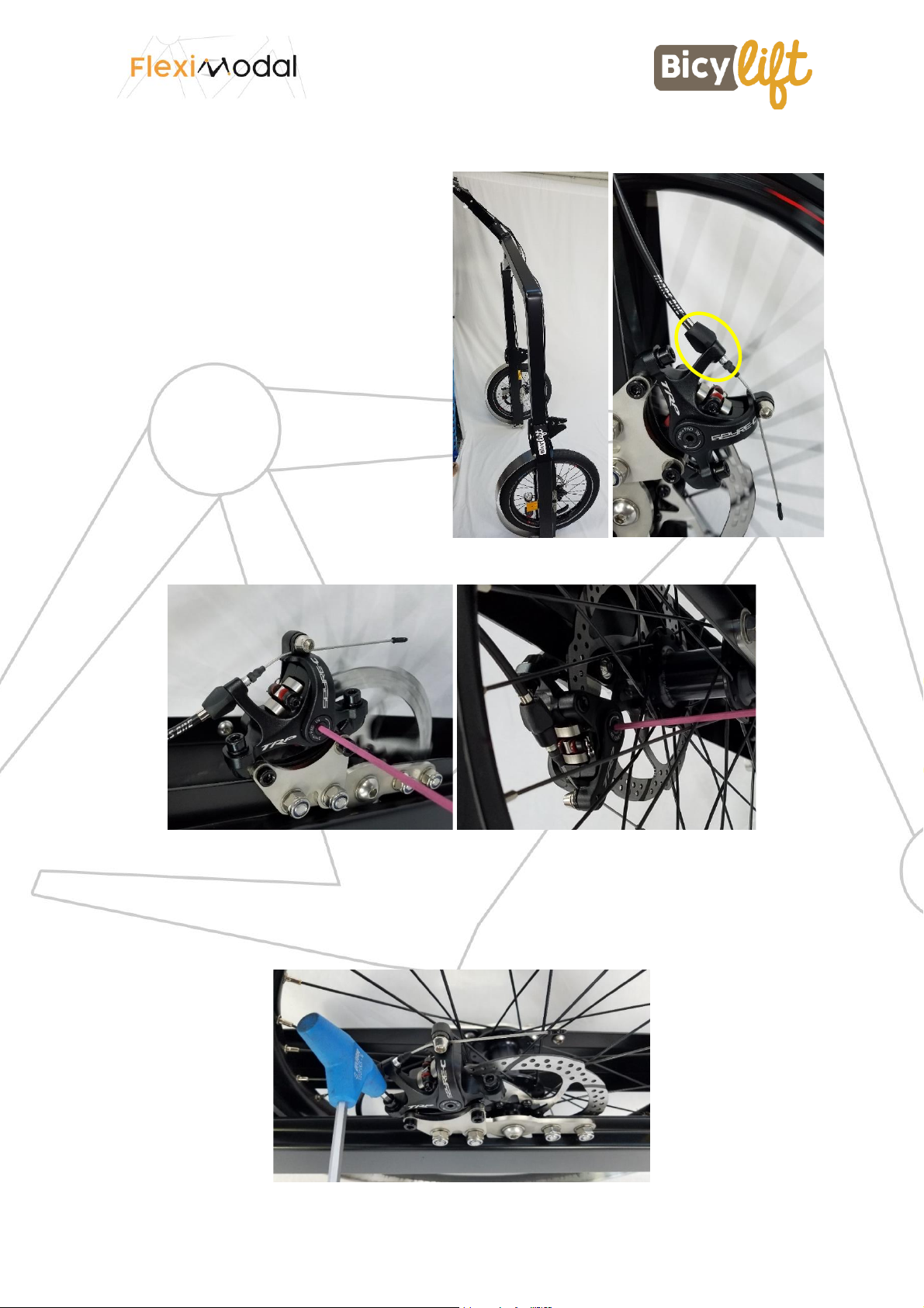
Settings & repairs
•Setting the braking system
For easy adjustment, use the black knurls
on the brake calipers to adjust cable
tension.
Place the brake caliper upright against a
wall and let the wheel turning while
adjusting with the knurl so that the pads
are as close to the disc as possible without
touching it.
If the adjustment with the knurl is not
sufficient because it reaches the end of its
travel, you can screw it back a few turns
and adjust the position of each brake pad
in its caliper. To do this, use a 3mm Allen
key (pictures below). Let the wheel turning
and screw to move the pad as close as
possible to the disc without it touching the
disc.
•If the pads are no longer parallel to the brake disc
It is possible to realign the bracket by unscrewing the two M6 support screws with a 5mm
Allen key.

11/13
•If the brake lever does not return properly.
Check sheaths and cables. Check that the brake cables are securely attached to the brake
calipers at the wheels.
•Change the sheaths and cables or if problem not solved
1. Remove the brake cable ferrule
2. Unscrew the grey screw that locks the brake cable to the caliper.
3. Remove the brake cable from the caliper.
4. Remove the plastic clamps that secure the sheaths to the trailer frame.
5. At the brake handle of the drawbar, unscrew the M5 screw with a 4mm Allen key and
a 10mm open-end wrench.
6. Remove the entire brake system and replace the brake lines or cables if necessary.
Sheath left: 165cm, right: 245cm. Caution, use only low compression tubing such as
Kevlar tubing.
Hitch trailer/bike
Checkpoints
•Bike hitch
Check that the bike hitch ball is vertical and free of any abnormalities.
Check the attachment of the BicyLift attachment to the bicycle (tightening of screws,
condition of the clamps, etc.).
•Trailer hitching system
Make sure that the bushing that slides on the trailer hitch does not
have the corners bent so that the hitch ball can escape. A deformation
is observed when the bike/trailer angulation is too large.
Maximum angles
•Check that all screws are properly tightened.
12/13
Settings & repairs
•Disassembly of the hitch
1. Unscrew the grey screw with a large flat screwdriver OR the
black screw if previous model with a 4mm Allen key (screw
with threadlocker).
2. Unscrew the black brake control screw with a 3mm Allen
key.
3. Unscrew the hollow screw with a 13mm wrench (screw
with threadlocker).
4. Pull out the coupling system
5. To remove the ring from the coupling, unscrew the wing
knob by hand or the CHC screw with a 3mm wrench.
6. Pull out the bushing
Drawbar
Checkpoints
•Check that the lever is firm in the 3 fixed positions of the drawbar, that it has no
rotational play.
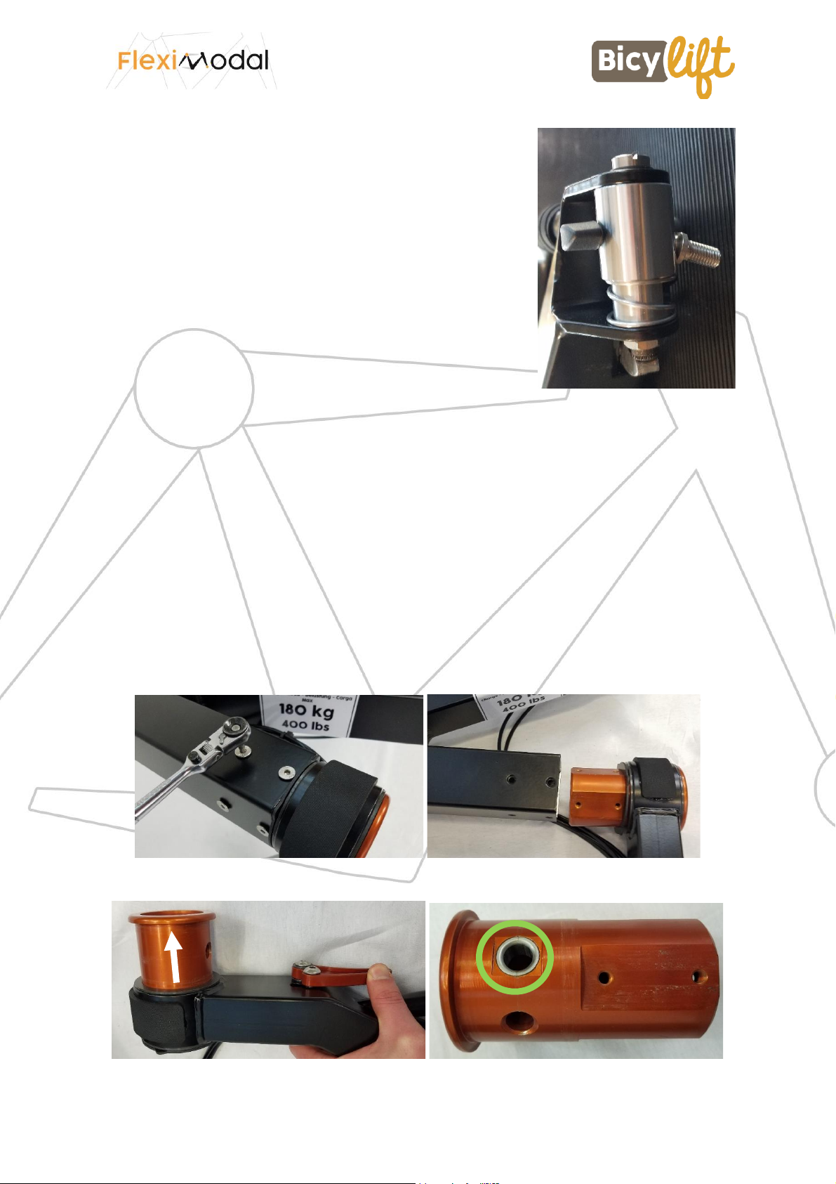
Settings & repairs
•If the rotation becomes complicated, or a position has difficulty passing
Check the indexing ring on the drawbar.
1. Remove the 8 screws from the trailer frame with a 4mm Allen key.
2. Pull out the drawbar
3. Press the tiller position lever and pull the indexer out of the drawbar
1
2
3
5

13/13
4. Check that the indexing ring is in good condition and does not protrude from its
housing. If this is the case, contact us.
5. Reassemble the indexer, taking care to ensure that it is correctly oriented. For
example, refer to the standing position of the drawbar, which must be at right angles
to the frame tube.
Need advice or spare parts: contact us!
contact@fleximodal.fr
+33 222 930 940
Other manuals for BicyLift
1
Table of contents
Popular Utility Vehicle manuals by other brands

Westward
Westward GO-4 EV INTERCEPTOR IV Operator's manual

DK2
DK2 MMT4X6OG user manual

Federal Signal Corporation
Federal Signal Corporation LEACH 2R-III Service manual

Great Dane
Great Dane 42101203 Operator's manual

Arctic Cat
Arctic Cat PROWLER XT Operator's manual

Snapper
Snapper GROUNDS CRUISER GC9520KW parts manual

Razor
Razor Ground Force owner's manual

Kendon
Kendon Stand-Up TRIKE/SPYDER/SIDECAR Ride-Up SRL owner's manual

Toro
Toro Workman GTX Series installation instructions

ShoreLand'r
ShoreLand'r 69175 Series Service manual

Sodikart
Sodikart Sigma User maintenance guide

CBS Products
CBS Products C-823-13 Operating and maintenance manual


