Great Dane 42101203 User manual

operator’s manual
warning: This manual contains important safety information.
Read manual carefully. Keep manual with trailer at all times.
drive away with more
operator’s manual
for van and platform trailers

table of contents
Operator’s Instructions ..........................................1
Controlled-Temperature Trailers............................2
Coupling and Uncoupling ..................................3-7
Proper Use of Steps and Handholds ................8-9
Normal Use..........................................................10
Weight Distribution for Van Trailers................11-14
Weight Distribution for Platform Trailers........15-16
Procedure for Extending and
Closing Extendable Trailers .......................17-18
Pre-Trip Inspection.........................................19-24
Electrical System .................................................25
Wiring Diagram ....................................................26
Fifth Wheel and Kingpin Engagement ................27
Suspension Slider ..........................................27-30
Qwik elease®......................................................29
Brakes and Air Systems.................................31-32
Tires......................................................................32
Tire Loads ............................................................33
Spare Tire.............................................................34
ims and Wheels ...........................................35-40
Hubs.....................................................................41
Axle Alignment.....................................................42
Leaf-Spring Suspension......................................42
Air-Spring Suspension.........................................42
Exhaust (Dump) Valve Operation ........................43
Supports (Landing Gear) .....................................44
Parking Brakes.....................................................45
Antilock Brake System ........................................46
ear, Side and Vent Doors.............................47-48
Warranty...............................................................49
eporting Claims and Safety Defects.................50
Service ecord...............................................51-52
Notes....................................................................53

2
his manual has been prepared to assist you in retaining the safety, dependability, and performance that
are built into Great Dane trailers. It is essential that this trailer receives periodic inspections, maintenance,
and service parts replacement.
his manual includes safety checks that the operator should perform periodically.
It is important that every trailer owner and/or operator have an organized railer Preventive Maintenance
( PM) program. he United States Department of ransportation requires that the maintenance records
be kept on every commercial highway vehicle. It is to your advantage to be able to show that regularly
scheduled PM inspection checks have been made on every piece of equipment operated. A regular
PM program will assure that you get the most from your Great Dane trailer.
You can get help in setting up your trailer preventive maintenance program by sending for a railer
Maintenance Manual. Contact the ruck railer Manufacturers Association, Alexandria, Virginia:
(703) 549-3010 (www.ttmanet.org).
perat r’s instructi ns
imp rtant
Read this manual carefully. Should you have any questions, contact the Great Dane Trailers
Customer Service Department immediately for the answers. This manual should be kept with the
trailer at all times and should remain with the trailer when it is sold. Replacement manuals
Part No. 42101203 can be purchased from Great Dane authorized service parts facilities.
It is important that owners and drivers of controlled-temperature trailers be well informed about the
trailers limitations and to operate such trailers within their limitations to ensure safety and profitability
of the equipment. Following are some year-around guidelines, which are applicable to controlled-
temperature trailers:
1. Do not haul frozen foods in trailer designed only to haul chilled products.
2. Do not install a larger capacity mechanical refrigeration unit in a trailer with inadequate insulation
and hope to get the job done.
3. Match trailer insulation performance with refrigeration unit output for highest efficiency.
4. Do not expect the trailer to act as a freezer. Products to be hauled should be loaded at a temperature
as cold as or colder than the required temperature of the products at the time of delivery.
c ntr lled-temperature trailers
cauti n:
Controlled-temperature trailers are designed to transport food and food products.
The vehicle must be clean before loading. DO NOT transport products or use cleaning
agents in these trailers that could cause contamination of any food product.
1

4
Step 5: Secure Tractor
• Put on the parking brake.
• Put transmission in neutral.
Step 6: Check Trailer Coupler Height
• The trailer should be low enough that it is
raised slightly by the tractor when the tractor
is backed under it. Raise or lower the trailer as
needed. (If trailer is too low or too high, tractor
may strike and damage nose of the trailer,
or it may not couple correctly.)
• Check that the kingpin and fifth wheel are
aligned.
Step 7: Connect Air Lines to Trailer
• Check coupler seals and connect tractor
supply (emergency) air line to trailer supply
(emergency) coupler.
• Check coupler seals and connect tractor
control (service) air line to trailer control
(service) coupler.
• Make sure air lines are safely supported where
they will not be crushed or caught while tractor
is backing under the trailer.
Step 8: Supply Air to Trailer
• From cab, push in “Air Supply” knob or move
tractor protection control valve from the
“Emergency” to the “Normal” position to
supply air to the trailer brake system.
• Wait until the air pressure is normal.
• Check brake system for crossed air lines.
– Shut engine off so you can hear leaks
in the brake system.
– Apply and release trailer brakes. Listen for
sound of trailer brakes being applied and
released. You should hear the brakes move
when applied and air escape when the
brakes are released.
– Check air brake system pressure gauge
for signs of major air loss.
• When you are sure trailer brakes are working,
start engine.
• Make sure air pressure is up to normal
Step 9: Lock Trailer Brakes
• Pull out the “Air Supply” knob, or move the
tractor protection control valve from “Normal”
to “Emergency.”
3
c upling and unc upling
Knowing how to couple and uncouple correctly is basic to the safe operation of combination vehicles.
General coupling and uncoupling steps are listed below. here are differences between various combinations
of tractors and trailers. Learn the specific details of coupling and uncoupling the vehicles you will operate.
warning: Incorrect coupling and uncoupling can result in serious injury or death.
Step 1: Inspect Fifth Wheel
• Check for damaged/missing parts
• Check to see that mounting to tractor is secure,
no cracks in frame, etc.
• Be sure that the fifth wheel plate is lubricated
as required. Failure to keep the fifth wheel plate
lubricated could cause steering problems
because of friction between the tractor and
the trailer.
• Check if fifth wheel is in proper position
for coupling:
– Wheel tilted down towards rear of tractor.
– Jaws open.
– Safety unlocking handle in the automatic
lock position.
• If you have a sliding fifth wheel, make sure
it is locked in place.
• Make sure the trailer kingpin is not damaged.
Step 2: Inspect Area
• Make sure area around the vehicle is clear.
• Be sure trailer parking brakes are applied.
• Check that cargo is secured against movement
caused by the tractor being coupled to the trailer.
Step 3: Position Tractor
• Back the tractor directly in front of the trailer.
(Never back under the trailer at an angle,
because you might push the trailer sideways
and damage the support legs).
• Check position, using outside mirrors,
by looking down both sides of the trailer.
Step 4: Back Slowly
• Back until fifth wheel just touches the trailer.
• Do not hit the trailer.
COUPLING Tractor-Semi Trailers

6
• With the front of the trailer supported by
the tractor,
– Check for enough clearance between rear of
tractor frame and support legs. (When trac-
tor turns sharply it must not hit the support
legs or their bracing.)
– Check that there is adequate clearance
between the top of the tractor tires and the
underside of the trailer.
Step 1: Position Rig
• Make sure surface of parking area can support
weight of trailer.
• Have tractor in a straight line with the trailer.
(Pulling out at an angle can damage the
support legs and upper coupler.)
Step 2: Ease Pressure on Locking aws
• Shut off trailer air supply to lock trailer brakes.
• Ease pressure on fifth wheel locking jaws by
backing up gently (this will help you release
the fifth wheel locking lever).
• Apply parking brakes while tractor is pushing
against the kingpin. This will hold the tractor
with pressure off of the locking jaws.
Step 3: Lower the Support Legs
• Lower the support legs until they make firm
contact with the ground. Turn crank in low gear
a few extra turns. This will lift some weight off
the tractor. (Do not lift trailer off the fifth wheel).
This will make it easier to unlatch fifth wheel
and couple next time.
5
Step 10: Back Under Trailer
• Use lowest reverse gear.
• Back tractor slowly under trailer to avoid hitting
the kingpin too hard.
• Stop when the kingpin is locked into
the fifth wheel.
Step 11: Check Connection for Security
• Raise trailer support legs slightly off ground.
• Pull tractor gently forward while the trailer
brakes are still applied.
Step 12: Secure Tractor-Trailer
• Put transmission in neutral.
• Put parking brakes on.
•Shut off engine and take key with you
so someone else will not move the
tractor-trailer while you are under it.
Step 13: Inspect Coupling
• Use a flashlight if necessary.
• Make sure there is no space between upper
coupler and fifth wheel. If there is space, some
thing is wrong (kingpin may be on top of closed
fifth wheel jaws; trailer can come loose very easily).
• Go under trailer and look into the back of the
fifth wheel. Make sure the fifth wheel jaws have
closed around the shank of the kingpin.
• Check that the locking lever is in the
“lock” position.
• Check that the safety catch is in position over
locking lever. (On some fifth wheels the catch
must be put in place by hand.)
• If the coupling is not right, do not drive the
coupled unit; get it fixed.
Step 14: Connect the Electrical Cord
and Check Air Lines
• Plug the electrical cord into the trailer and fasten
the safety catch.
• Check both air lines and electrical line for signs
of damage. Repair or replace if necessary.
• Make sure air and electrical lines will not hit any
moving parts of vehicle.
Step 15: Raise Trailer Support Legs
(Landing Gear)
• Use low-gear range (if so equipped) to begin
raising the support legs. Once free of weight,
switc h to the high-gear range.
• Raise the support legs all the way up. (Never
drive with support legs only part way up as they
may catch on railroad tracks or other things.)
• After raising the support legs, properly secure
the crank handle.
COUPLING Continued
UNCOUPLING Tractor-Semi Trailers
he following steps will help you to uncouple safely.
warning: Incorrect coupling and uncoupling can result in serious injury or death.

Use all steps and handholds with extreme caution. Such components are subject to wear, damage and
environmental conditions. Make sure these components are firmly attached and properly maintained.
If you suspect that they are not, do not use them. If steps are wet, iced or for some reason seem to be
slippery, they must not be used.
Steps and handholds are provided on the front wall corners as part of optional vent door packages.
They should only be used for access to the vent door. They must not be used to start, inspect or
maintain any heating or cooling unit installed on the front wall of the vehicle.
On Classic models, no attempt should be made to secure a vent in an open position unless the snap
hook-type vent holdback is securely installed and functioning.
CLIMBING PRACTICES
1. Store clipboards and all other objects prior to climbing. Hands must be free.
2. Face inward (toward the trailer) at all times while ascending and descending.
3. Maintain a three-point contact at all times.
4. Wear slip-resistant footwear.
ACCESS FROM THE GROUND
Use the front wall steps only when the trailer is properly supported by extended support legs. You must
use a step ladder, or other structure specifically designed for the purpose of ascent and descent, of an
adequate height to safely reach the bottommost step.
pr per use f steps and handh lds
87
An informative video, “Hooking Up Doubles”, showing the TMC recommended method of safely
coupling and uncoupling multiple trailers, is available from the Technology and Maintenance Council
of ATA. Telephone: 703-838-1763.
Step 4: Disconnect Air Lines and
Electrical Cable
• Disconnect air lines from trailer. Connect air line
couplers to dummy couplers at back of cab.
• Hang electrical cable with plug down to prevent
moisture from entering it.
• Make sure lines are supported so they will not
be damaged while driving the tractor.
Step 5: Unlock Fifth Wheel
• Raise release handle lock.
• Pull the release handle to “open” position.
• eep legs and feet clear of the rear tractor
wheels to avoid serious injury in case the
vehicle moves.
Step 6: Pull Tractor Partially Clear of Trailer
• Pull tractor forward until fifth wheel comes out
from under the trailer.
• Stop with tractor frame under trailer (prevents
trailer from falling to ground if support legs
should collapse or sink).
Step 7: Secure Tractor
• Apply parking brake.
• Place transmission in neutral.
Step 8: Inspect Trailer Support
• Make sure ground is supporting trailer.
• Make sure support legs are not damaged.
Step 9: Pull Tractor Clear of Trailer
• Release parking brakes.
• Check and drive tractor clear.
UNCOUPLING Continued

1. This trailer was built to carry cargo within the
limitations of weight ratings shown on the
certification label. These ratings, GAWR and
GVWR are:
a. The GAWR (gross axle weight rating) is the
structural capability of the lowest rated
member of the running gear components:
suspension system, hubs, wheels, drums,
rims, bearings, brakes, axles, or tires.
b. The GVWR (gross vehicle weight rating) is
the structural capability of the trailer when
supported by the upper coupler and axles
with the load uniformly distributed through-
out the cargo space. CAUTION! The
maximum load indicated on the certification
label may or may not be a legal load on the
highway you plan to use.
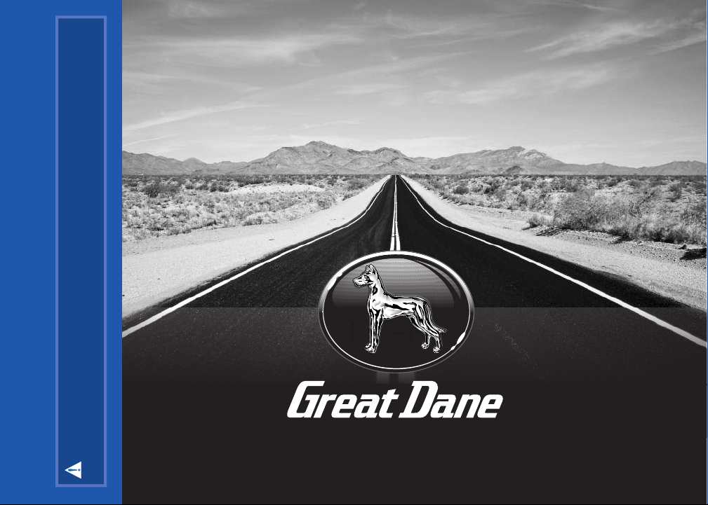
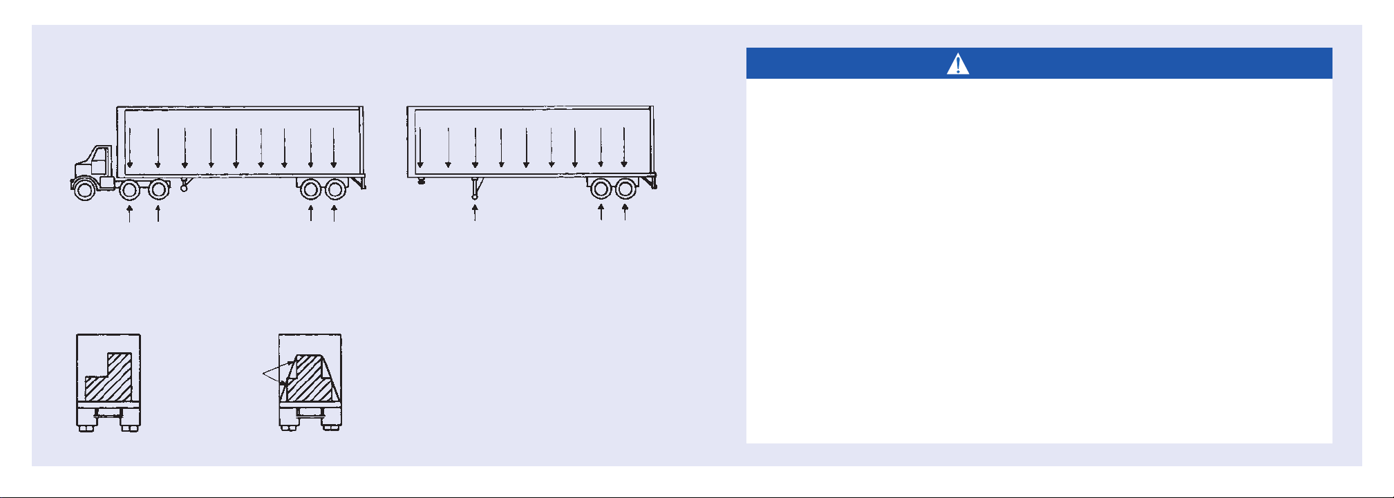
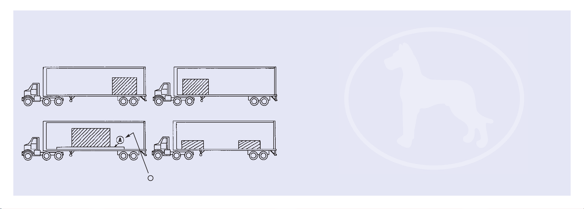
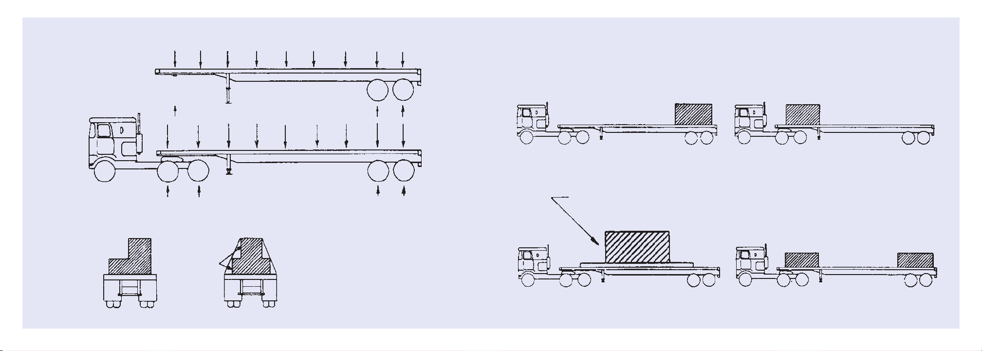
2. This trailer will carry a total payload equal to
the Gross Vehicle Weight Rating (GVWR) less
the weight of the trailer. The load must be
uniformly distributed, or it must be uniformly
distributed except for up to 25,000 pounds
that must be evenly distributed in any 10 linear
feet of trailer length. Recommended payload
distributions are shown in Figures 1, 2, and 3.
3. NOTE: Exceptions to the above are meat rail
trailers. For the maximum allowable suspended
load, see the vehicle certification label.
4. The cargo should be properly loaded, blocked,
and braced to prevent load shifts and to
comply with the following sections of the
Department of Transportation Federal Motor
Carriers Safety Regulation, Subpart 1 –
Protection Against Shifting or Falling Cargo:
Section 393.100 – General rules for protection
against shifting or falling cargo.
Section 393.102 – Securement systems.
Section 393.104 – Blocking and bracing.
Section 393.106 – Front-end structure.
n rmal use
10
ACCESS FROM THE TRACTOR
If the tractor is not equipped with adequate steps, handholds and slip-resistant deck plate to the rear
of the cab, Do Not Attempt Access To The Trailer Steps From The Tractor. Use “Access From The
Ground” method. If the tractor is properly equipped with steps, handholds and a deck plate and the
tractor is coupled and locked to the trailer, it is most important that the tractor be in a partial “jackknife”
orientation. The tractor must be positioned such that the deck plate is directly beneath the lowest step.
9
warning: Walk carefully in the trailer. The
floor may be slippery. Enter and leave only from a
dock as high as the floor or by means of a substan-
tial ladder. Advise others of these precautions.
cauti n: Operation of the trailer outside
the limitations of this manual is against federal law
and Great Dane Trailers’ design criteria. Any opera-
tion exceeding the limitations stated will void any
responsibility of Great Dane Trailers for the results.
1. DO NOT climb on steps not firmly attached and properly maintained.
2. DO NOT climb on steps with any item in your hands.
3. DO NOT use a tractor not equipped with a safe, adequate climbing system to access the
trailer’s front wall steps.
4. DO NOT step on tires, fenders, tractor frames, or mudflap supports.
5. DO NOT step over air and electrical lines between the tractor and the trailer. Disconnect and
properly store if necessary.
6. DO NOT use any portion of the tractor in conjunction with any portion of the trailer
simultaneously in a “spread-eagle” hold or stance for support.
7. DO NOT use an access system if wet, iced, or for any reason seems to be slippery.
8. DO NOT use a trailer’s front wall access system to start, inspect, or maintain any heating or
cooling unit.
9. DO NOT climb higher than necessary to open, secure or close the vent door.
10. DO NOT remain on a trailer’s access system while the trailer is being coupled to or uncoupled
from a tractor.
11. DO NOT jump from the trailer to the ground.
warning:
his Great Dane trailer was designed for operation within legal highway speed limits on reasonable
road surfaces in accordance with the following:

1211
warning:
PREVENT TRAILER ROLLOVER
THESE INSTRUCTIONS MUST BE FOLLOWED TO MAXIMIZE TRAILER STABILITY
AND MINIMIZE ROLLOVER HAZARD WITH SUSPENDED MEAT CARGO. ANY
CARGO MOVEMENT UNDER ADVERSE HANDLING CONDITIONS, SUCH AS AN
ACCIDENT AVOIDANCE MANEUVER, MAY CAUSE VEHICLE INSTABILITY AND
RESULT IN ROLLOVER
LOADING
1. LOAD HINDQUARTERS AND FOREQUARTERS IN SEPARATE GROUPS.
2. PAC SUSPENDED MEAT CUTS TIGHTLY TOGETHER AND TIGHTLY AGAINST
WALLS TO MINIMIZE CARGO MOVEMENT.
3. USE LONG MEAT HOO S AND DOUBLE HOO ING WHERE POSSIBLE TO LOWER
LOAD CENTER OF GRAVITY. EEP VERTICAL SPACE BETWEEN TRAILER FLOOR
AND BOTTOM OF MEAT CUTS TO A MINIMUM.
4. BALANCE WEIGHT OF SUSPENDED MEAT CUTS EVENLY FROM SIDE TO SIDE TO
EEP LOAD CENTER OF GRAVITY OVER CENTER OF TRAILER.
5. DO NOT OVERLOAD TRAILER. SEE CERTIFICATION PLATE FOR GROSS VEHICLE
WEIGHT RATING (GVWR) AND GROSS AXLE WEIGHT RATING (GAWR).
6. MAXIMUM ALLOWABLE SUSPENDED LOAD, INCLUDING HOO S, IS 40,000 LBS
(18,144 G) UNIFORMLY DISTRIBUTED, NOT TO EXCEED 833 LBS (378 G) FOR
EACH FOOT OF TRAILER LENGTH.
weight distributi n f r van trailers
FIGURE 1.
FIGURE 2.
Trailers are designed for uniform load distribution as shown.
The load should be distributed uniformly from front to rear.
Secure against
lateral load
movement.
Crosswise weights should be equally distributed.
A heavy load should not be loaded on one side
because this will overload springs and tires on
that side. Place load so that weight will be equal
on rear tires, eliminating possible twisting of the
frame and overloading of axle housings and
wheel bearings.
WRONG RIGHT
Continued

1413
weight distributi n f r van trailers Continued
FIGURE 3.
WRONG WRONG
RIGHT
Use a skid of adequate length and construction to
properly distribute weight front to rear.
RIGHT
A
Loading heavy concentrated loads not occupying
full trailer floor area
[ This page intentionally left blank ]

16
Loading heavy concentrated loads not occupying
full trailer floor area
WRONG WRONG
15
weight distributi n f r platf rm trailers
FIGURE 1.
FIGURE 3.
Trailers are designed for uniform load distribution as shown. The load should be distributed
uniformly from front to rear.
Crosswise weights should be equally
distributed. A heavy load should not be
loaded on one side because this will over-
load springs and tires on that side. Place
load so that weight will be equal on rear
tires, eliminating possible twisting of the
frame and overloading of axle housings
and wheel bearings.
Secure against
lateral load
movement.
FIGURE 2.
Use a skid of adequate length and construction to properly distribute weight front to rear.
RIGHT RIGHT

DO NOT SUPPORT
LOAD IN THIS AREA
CLEARANCE MUST BE EPT
NOTES:
1. Bolsters must be used
for blocking to avoid
damage to inner sec-
tions of beams.
2. Position bolsters as far
away from open section
as possible to avoid
breaking of neck and
front of rear section.
3. If sliding tandem is
used, move slide
forward for best
loading.
4. Chain tie downs
must be of sufficient
capacity and must be
tightly secured.
Overall Lengths: 40' closed
65' open
Rigid, Self supporting load
flexible load
5' MIN
25' MAX
18
extending and cl sing extendable trailers
17
To Extend the Trailer:
1. Charge the brake system
2. Apply the trailer brakes.
3. Operate the handle on the locking pin
actuator to retract the locking pins.
4. Pull the tractor ahead until the locking pins
are just short of the desired locking hole.
5. Operate the handle on the locking pin
actuator to move the pins into the locking
position.
6. Pull the tractor forward until the pins
engage the locking holes. Make visual
check to be sure both pins are clearly
through the inner beams.
To Close the Trailer:
1. Charge the brake system
2. Apply the trailer brakes.
3. Operate the handle on the locking pin
actuator to retract the locking pins.
4. Back the tractor until the locking pins
are just short of the desired locking hole.
5. Operate the handle on the locking pin
actuator to move the pins into the locking
position.
6. Back the tractor until the pins engage the
locking holes. Make visual check to be sure
both pins are clearly through the inner beams.
LOAD RATINGS:
Rigid, self-supporting loads: 60,000 lbs.
Flexible, non-self-supporting loads (lbs.):
warning: Stay clear of open area while extending and closing.
OVERALL LENGTH 40-65 45-75 48-80 53-90
45' 50,000 ———
50' 40,000 45,000 ——
53' ——44,000 —
55' 32,000 35,000 ——
58' ——34,000 43,000
60' 28,000 28,000 ——
63' ——28,000 35,000
65' 25,000 25,000 ——
68' ——23,000 30,000
70' — 21,000 ——
73' ——21,000 26,000
75' — 18,000 ——
78' ——19,000 22,000
80' ——18,000 —
83' —— —19,000
88' —— —18,000
90' —— —15,000

20
3. Sound the horn, test for excess amount
of wheel play.
4. Test washer-wiper and examine
windshield for cracks.
5. See if mirrors on both sides of the cab
are clean and aligned.
6. Test heater-defroster blower.
8. Turn on all lights (low beam head-
lamps), emergency flasher and apply
trailer parking brakes.
7. Check for charged fire extinguisher and
emergency equipment.
Inspection procedure
before each trip
Even though the responsibility for checks and
adjustments of a vehicle may belong to the shop
or mechanical department, an operator should
never take the condition of a tractor or trailer for
granted. For the operator’s own best interest,
and because it is a Federal Motor Carrier Safety
requirement, it is important to make thorough
pre-trip inspections, on-the-road observations,
and written reports on the equipment on a
regular basis.
pre-trip inspecti n
19
Approaching vehicle
Look for oil, water, or fuel leaks.
Inside cab
1. Apply parking brake, start engine.
2. Check oil pressure, warning lights, air pressure. Deplete pressure
until warning buzzer sounds
warning:
When you make inspections, hookups, or
repairs, be careful how you position your
body, because the trailer or tractor might
move unexpectedly and cause injury.

22
8. Inspect and clean sidemarker lights and reflectors. 11. Inspect and clean conspicuity tape.
7. Where applicable, check for proper placard and shipping papers. 9. Where applicable, inspect sliding tandem lock.
10. Inspect trailer wheels and tires. Listen for air system leaks.
21
3. Make sure fifth wheel is locked.
4. See if electrical connector is firmly seated
and that cord is free from chafing.
6. Make sure the landing gear is raised and
the handle is securely stowed in the crank
handle holder.
5. Inspect air hoses for chafing, air leaks,
and proper support.
1. Make sure the fuel tank cap is tightly
secured, no leaks.
2. Examine rear tractor wheels, wheel nuts
and tires. Check tires for proper inflation
and abnormal wear.
Leave cab (engine running) & walk toward rear

24
2. Inspect headlamps, clearance lights, identification lights,
flashers, and turn signals.
Front of tractor
1. Inspect front tires, wheels and wheel nuts.
23
1. See if all lights are working properly, and clean as required. 2. Make sure all doors are secured.
Rear of trailer
warning:
Most pre-trip inspections are visual.
Check electrical wiring, brake hoses
and other brake components, distorted or
broken structural components and welds.
Report all defects to the proper persons
before deciding to start your trip.
Back in cab
1. Depress dimmer switch, observe
high-beam light.
2. With trailer brakes still on, release tractor
brakes and (in first gear) gently engage
clutch to test tractor-trailer coupling.
3. Apply foot brake for one minute. Air loss
should not exceed 4 psi per minute
for combination rig.
Right side of vehicle
Inspect lights, reflectors, tires, and wheels as
was done for the left side.

26
7 COND MAIN
HARNESS
4 COND ABS
HARNESS
BLUE
WHITE
WHITE-GREEN
RED
FRONT
GREEN
BROWN
WHITE
RED
BROWN
WHITE
BROWN
RED
BROWN
WHITE
YELLOW
BROWN
WHITE
BLAC
BLAC
BROWN
WHITE
WHITE W/GREEN
YELLOW
BROWN
WHITE
BROWN
TOP VIEW OF TRAILER
GREEN
BROWN
WHITE
The electrical system on every Great Dane trailer
meets or exceeds all federal and state requirements
in effect at the time of manufacture. Wherever
required by law, lamps and reflectors are marked
by the manufacturer to indicate the appropriate
specification with which each complies.
For optimum performance and long life from the
trailer’s lamps and wiring, follow this inspection
procedure.
Clean all reflectors and lamps. See that all lamps
burn properly. Replace all burned out lamps and
broken reflectors. Factory approved replacement
parts should be used, and replacement bulbs of
equal candlepower should be used for safety.
Use only a 12-volt DC battery for checking lamps
or antilock brake systems. Never use battery
chargers or transformers.
Inspect all wiring to see that it is not frayed, and
that it is properly supported and protected, with all
connections tight. See that the electrical cable is
clean and long enough to permit “jackknife”
maneuvers. Be certain that the cable is supported
so that it cannot be pinched or entangled by the
lower and upper couplers. eep the plug on the
electrical cable and the receptacle on the trailer
free of corrosion.
electrical system
25
T AILE IS EQUIPPED WITH ANTILOCK B AKE SYSTEM (ABS). NO. 7 (BLUE)
CI CUIT IS ESE VED FO CONTINUOUS POWE SUPPLY TO ABS FO MOST
EFFECTIVE ABS OPE ATION, TOWING VEHICLE MUST SUPPLY MINIMUM OF 10
AMPS AT 12.5 VOLTS ON NO. 4 ( ED) & NO. 7 (BLUE) CI CUITS.
PIN COLO CI CUIT
1 WHITE G OUND ETU N TO TOWING VEHICLE
2 BLACK CLEA ANCE, SIDE MA KE & ID LAMPS
3 YELLOW LEFT TU N SIGNAL & HAZA D LAMPS
4 ED STOP LAMPS & ABS POWE
5 G EEN IGHT TU N SIGNAL & HAZA D LAMPS
6 B OWN TAIL, LICENSE, CLEA ANCE &
SIDE MA KE LAMPS
7 BLUE ABS CONTINUOUS SHA ED POWE
FAILU E TO HEED THIS WA NING CAN ESULT IN P OPE TY
DAMAGE, SE IOUS INJU Y O DEATH.
warning:
J560
SOCKET
cauti n: See Connector Wiring Change caution inside front cover.
wiring diagram
Never replace fuses or breakers with metal foil or
other devices.
A decal, similar to the one shown here, is located
on the front of each trailer. You may trace individ-
ual electrical circuits by the wire colors indicated.
Refer to the schematic drawing and the decal for
conductor numbers and wire colors.
warning:
Do not exceed 21 candlepower for dome
lamps. Stronger bulbs may generate
excessive heat and start a cargo fire.
Cargo must be kept away from dome
lamps. Dome lamps must be turned off
for over-the-road operation.

28
The slider shown may or
may not be used on this
vehicle. However, opera-
tions will be similar.
The slider likely will be equipped with a
Binkley Qwik Release®
. See instructions
on the next page for proper operation.
Inspect the kingpin and the upper
coupler on the trailer at regular
intervals to be sure that they have
not suffered damage or undue
wear. Although the kingpin is made
of hardened forged steel, it is still
subject to wear and can be chipped
or broken with abuse. Always
check the bottom locking flange
of the kingpin to determine its
condition. The upper coupler
fasteners should be inspected to
see that they are in place and
properly tightened.
Before coupling the trailer to its
tractor be certain that the tractor
fifth wheel is properly lubricated
and the fifth wheel jaws are open
to receive the kingpin.
fifth wheel
and kingpin
engagement
27
slider f r van trailers
1. If your trailer has a sliding undercarriage, visually
inspect to see that all four locking pins have fully
penetrated the upper slide rails and locked before
moving the trailer.
2. The slider may be equipped with a manual stop bar
that should be in good working order. If so, this bar
should always be locked in place immediately
behind the slider unit when the trailer is being
operated unless slider is in rearmost position, then
place manual stop bar just in front of slider.
3. Be certain that the slider hold-downs are fastened
in place and properly situated to prevent separation
of the lower slide unit

29
slider f r
platf rm trailers
1. If your trailer has a sliding undercarriage, visually
inspect to see that all four locking pins have fully
penetrated the web of the main beam and
locked before moving the trailer. Anytime the
body of a locking pin does not protrude past the
outside surface of its mating hole, retract and
release the pins until they do. Sometimes rocking
the trailer back and forth will free a binding
condition between the slider and the trailer,
allowing the pins to work freely.
2. Always check the condition of the holes in
the main beam. Holes that are badly worn or
elongated will result in undue slack in the slider
unit, causing excessive wear and suspension
misalignment.
3. Always check to see that the hold-down
brackets are in good repair and have not been
damaged. Trailers should not be operated if
any of these brackets are not in proper position.
4. Check the pin cage assembly bolts for tightness
after each year of service. Re-torque to 380 lb-ft.
30
OCKING PIN SHOWN
WITH PROPER PIN
ENGAGEMENT
OCKING PIN
OCKING PIN
S IDE PAD
HO D-DOWN
BRACKET
MAIN BEAM
Detail (A)
LOCKING PIN AND HOLD-DOWN ASSEMBLY
Qwik Release®
Many sliding running gear assemblies are
equipped with spring-loaded Qwik Release
device to retract the pins locking the
slider frame to the upper rails.
To Position Slider:
1. Remove stop bar and move to desired
location.
2. Lift pull arm and pull until locked in
the “out” position. If lock pins do not
retract after pull arm is lowered in the
“out” position, gently rock trailer with
brakes applied and pins will automati-
cally retract.
3. Apply trailer brakes and carefully move
trailer until contacting stop bar.
4. Release pull arm to the “in” position
and visually check all lock pins for
proper engagement.
5. Locate manual stop bar immediately
behind slider.

The trailer brake systems will perform safely and
efficiently only as long as you maintain them proper-
ly and do not abuse them. Trailer brakes should be
inspected and adjusted frequently in connection
with a Trailer Preventive Maintenance Program.
Out-of-adjustment brakes can cause increased
stopping distance, shorter brake component life,
and a greater tendency for the trailer to jackknife.
Care and Adjustment of Brakes
31
Proper operation of the brake systems requires a
firm seal between the air brake couplers. Inspect the
couplers for seal damage and cracked housings.
Inspect the air hoses for cracking and for frayed con-
nections. Replace or repair damaged components.
eep the air system clean. Air tanks should be
drained daily to remove moisture and other contami-
nants, especially during cold weather operations.
Use of additives as antifreeze in the air brake system
is not recommended. They may result in deterioration
of valve seals and performance of the brake system.
eep the air system tight. The air system cannot be
charged properly if there are leaks in reservoirs, lines,
hoses, or valves. Always check the tractor pressure
gauge for unusual drops or extended buildup times.
If you use Teflon tape or other thread sealers to seal
threaded connections in your air lines, be careful not
to allow pieces of the sealer to enter the air system.
They can clog passages into the valves.
Run the tractor engine until the air brake system
pressure gauge shows at least 105 psi.
With the engine still off, apply the brakes fully for two
minutes. The gauge reading drop should not exceed
four psi in one minute.
With the engine still off, slowly open the draincocks
in the trailer’s air tanks and allow the pressure to
drop gradually. The parking brakes should apply.
Remember that serious air losses are extremely
hazardous conditions that are likely to cause
accidents or breakdowns.
air system and brake perati n
Before entering traffic, check the operation of the
trailer brakes to be sure they are in good working
order. Operate the foot pedal, dash control valves,
and hand valve to assure brake application and
release in each instance. Listen for air leaks under
each condition.
check brake perati n
32
Do not over inflate. Check for proper inflation with
an accurate gauge when the tires are cold. Check
the spare too. Inspect tires for nails and other objects
embedded in the rubber, and for stones and other
objects lodged between duals. Examine tires to see
that they are free of breaks and other defects. Watch
new and retread tires for signs of failure during
break-in period. Dual tires on any axle end should
have the same diameter. Replace any tire that has fabric exposed through
the tread or sidewall, or that has less than
2/32" tread depth.
tires
NHTSA
Auto Safety Hotline
400 7th Street SW
Washington, DC 20590
Telephone: 800-424-9393
US Department of Labor
OSHA Publications Office
Room N-3101
Washington, DC 20210
Telephone: 202-523-9667
warning:
Do not operate this vehicle with any brake
defects or with brakes out of adjustment.
warning:
Tire and wheel/rim servicing can be
extremely dangerous and must be done
only by trained personnel using proper tools
and procedures. Information about tire and
wheel servicing can be obtained from:
cauti n:
Do not inflate tires above the maximum
inflation pressure molded on the tire by
the tire manufacturer. Tires must be
matched with proper compatible rims for
safe operation.

Do not overload the trailer tires. Overloading tires
creates a dangerous, unsafe condition that
should be avoided.
The total load per tire must not exceed the tire
manufacturer’s specified load carrying capacity at
stated inflation pressures for both tires and rims.
Great Dane Trailers, as required by the safety
regulations of the National Highway Traffic Safety
Administration, has assigned a Gross Axle Weight
Rating (GAWR) for each axle on the undercar-
riage. (See example certification plate below).
The GAWR and tire information shown on the
vehicle certification plate was applicable at the
time the trailer was manufactured. If the tires or
other components of the running gear have
been changed or altered since the trailer was
manufactured, the GAWR may have changed.
tire l ads
33
Tires and wheels are heavy. Use caution when
handling.
When you need to use or replace the spare tire,
move the trailer away from traffic to provide a
solid, safe working area.
To remove the spare tire from the carrier,
follow these steps:
1. Depress spring latch on hook (1).
Disconnect hook (1) from free end of chain (2).
2. Pull chain off the tire and remove the tire from
the tire carrier.
To replace the spare tire, follow these steps:
1. Slide the spare into the tire carrier as far as it
will go. Be sure the tire size and the carrier are
right for each other.
2. Run the chain through the center of the tire
and wheel and back to the starting point. Pull
the chain ends together as tight as possible.
3. Secure the chain by snapping hook (1) on the
free end chain (2).
spare tire
34
Snap Swivel
Chain Lock

Proper installation of rims and wheels on a vehicle
is essential to safe, economical, trouble-free
service. Use only the specified sizes of studs,
nuts, and clamps.
Recommended installation
procedure
Disc Wheels
Check all parts for damage, including wheels and
rings. Insure that studs, nuts and mounting faces
of hub and wheels are clean and free from grease.
Replace any defective parts.
Mount single wheel or inner dual wheel (also, outer
dual wheel for hub-type mounting) over studs,
being careful not to damage stud threads. Draw
up nuts alternately in the sequence as shown
above. Do not tighten them fully, however. This
procedure will permit the uniform seating of
nuts and insure the even face-to-face contact
of wheels and hub.
Tighten nuts fully, using the same alternate
sequence. Mount the outer wheel (for double cap
mounting) and repeat the entire procedure. In each
case, be sure to tighten wheel nuts only to the
torque level recommended in the table below and
to maintain them at that level through planned,
periodic checks. Note: When inner cap nuts are
retightened, be sure first to loosen outer cap nuts
several turns; then, retighten them.
rims and wheels
35 36
*NOTE: Rim and wheel nuts should be rechecked for proper torque
after vehicle has been operated for 50-100 miles, and every 25,000
miles thereafter, as well as during regular maintenance checks.
PREVENT WHEEL SEPARATION
RECOMMENDED TIGHTENING TORQUE FOR DISC WHEE
MOUNTING NUTS IS 450-500 B-FT. APP IES TO BA -SEAT
AND HUB-PI OT MOUNTING SYSTEMS WITH 3/4-16 OR M22
X 1.5 STUDS FOR A UMINUM AND STEE WHEE S. CHECK
NUTS FREQUENT Y (50-100 MI ES AFTER INITIA IN-SERVICE
DATE AND AT INTERVA S NOT TO EXCEED 25,000 MI ES)
AND TIGHTEN TO MAINTAIN RECOMMENDED TORQUE.
FAI URE TO HEED THIS WARNING CAN RESU T IN
PROPERTY DAMAGE, SERIOUS INJURY OR DEATH.
GREAT DANE LTD PART NO. 42100753
SD83410
warning
1
10
3
5
72
8
6
4
9
warning:
Do not intermix wheel types. Insufficient
mounting torque can cause wheel shimmy,
resulting in damage to parts and extreme
tire tread wear. Excessive mounting
torque can cause studs to break and
discs to crack in the stud hole area.
Table of contents
Other Great Dane Utility Vehicle manuals
Popular Utility Vehicle manuals by other brands

Land Pride
Land Pride Treker 4200NT Assembly instructions

Federal Signal Corporation
Federal Signal Corporation LEACH 2R-III Service manual

PRONAR
PRONAR T672ECO user manual

Midland
Midland SIDE DUMP GRAVEL TRAILER Operator's manual

Cushman
Cushman Titan 36V Owner's manual and service guide

Sodikart
Sodikart GT2 User maintenance guide

Polaris
Polaris Ranger 4x4 500 EFI 2007 owner's manual

DR
DR VERSA TRAILER PRO XL2000 Safety & Operating Instructions

Coleman Powersports
Coleman Powersports CK196-T 2021 owner's manual

TrailMax
TrailMax T-12-UT manual

PRONAR
PRONAR T683P user manual

Malone
Malone EcoLight MPG585 Checklist & Maintenance Manual