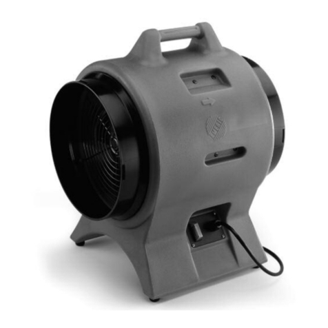
Flexxaire FX 2000 Series User manual

Printed in Canada June 14, 2007 Hydraulic Manual 01523r7.wpd Page 0-1
FLEXXAIRE® ENGINE TEMPERATURE
CONTROL SYSTEMS
FX 2000 FAN SERIES
(HYDRAULIC PITCH CONTROL)
GIF BOX IS CHECKED, REFER WITHIN FRONT COVER
PAGE OF THIS MANUAL FOR SPECIAL INSTRUCTIONS.
Publication No. 01523
Revision 7

Page 0-2 01523r7.wpd Hydraulic Manual June 14, 2007 Printed in Canada

Printed in Canada June 14, 2007 Hydraulic Manual 01523r7.wpd Page 0-3
Table Of Contents
SECTION 1. GENERAL INFORMATION ....................................................1-1
1.1. INTRODUCTION .........................................................1-3
1.2. IMPORTANT SAFETY INFORMATION ........................................1-3
1.3. FAN OVERVIEW .........................................................1-4
SECTION 2. HYDRAULIC FAN GROUP ....................................................2-1
2.1. INTRODUCTION .........................................................2-3
2.2. INSTALLATION ..........................................................2-4
2.3. SERVICE AND MAINTENANCE .............................................2-10

Page 0-4 01523r7.wpd Hydraulic Manual June 14, 2007 Printed in Canada

Printed in Canada June 14, 2007 Section 1 - General Information & Overview 01523r7.wpd Page 1-1
SECTION 1.
GENERAL INFORMATION
SECTION 1. GENERAL INFORMATION ....................................................1-1
1.1. INTRODUCTION ............................................................1-3
1.2. IMPORTANT SAFETY INFORMATION ...........................................1-3
1.2.1. Protective Equipment .......................................................1-3
1.2.2. Pressurized Items .........................................................1-3
1.2.3. Hot Fluids and Parts .......................................................1-3
1.2.4. Lifting ...................................................................1-3
1.2.5. Repairs .................................................................1-4
1.3. FAN OVERVIEW ............................................................1-5
1.3.1. Introduction ..............................................................1-5
1.3.2. Purging of the Radiator .....................................................1-5

Page 1-2 01523r7.wpd Section 1 - General Information & Overview June 14, 2007 Printed in Canada

Printed in Canada June 14, 2007 Section 1 - General Information & Overview 01523r7.wpd Page 1-3
1.1. INTRODUCTION
This manual (P/N 01523) is produced to assist in the
installation and operation of the Flexxaire®FX Series
fan systems.
Flexxaire®Manufacturing Inc. has made every effort
toensurethattheinformationcontainedinthismanual
is correct and complete at the time of printing.
Flexxaire®will assume no responsibility for any errors
or omissions. If you have any questions regarding this
manual or any other documents in the Technical
Support Package, please contact:
Flexxaire®Manufacturing Inc.
Product Support Department
10430 - 180 Street
Edmonton, Alberta, Canada
T5S 1C3
Phone: 780.930.6832 or 780.930.6836
Fax: 780.483.5499
Flexxaire®Manufacturing Inc. strongly advises that
any person(s) replacing parts on Flexxaire®’s
Hydraulic Pitch Control Fan has access to a
Flexxaire®Parts Book related to their fan assembly.
1.2. IMPORTANT SAFETY
INFORMATION
This manual is created to assist the customer in
part identification for the purpose of ordering
parts. This publication is used for maintenance,
servicing, and/or repair of the Flexxaire®Fan
Assembly.
The safety information in this publication is to be
used with all the safety information supplied from
the original machine manufacturer with the
machine that the Flexxaire®Fan Assembly has
been added to. Please refer to all safety
information supplied, prior to doing any work on
the Flexxaire®Fan Assembly or any other
component(s) to assure safety.
Improper operation, maintenance or repair of this
product can be dangerous and could result in
injury or death.
Do not operate or perform any lubrication,
maintenance or repair on this product, until you
have read and understand the operation,
lubrication, maintenance and repair information.
PleasecontactFlexxaire®or theirapproveddealer
for any information that you may require.
Theperson(s)servicingtheproductmaybeunfamiliar
with many of the systems or components on the
product. This makes it important to use caution when
performing any type of service work. A knowledge of
the product and/or its components is important before
the removal or disassembly of any component.
Because of the size of the product and/or its
components, the service person(s) should use proper
lifting procedures when removing the product and/or
any of its components.
1.2.1. Protective Equipment
Always wear protective glasses, protective shoes and
any other protective equipment as required by job
conditions when working around this product.
1.2.2. Pressurized Items
The hub and main shaft portions of the assembly are
under pressure during operation and may still have a
portion retained after operation. Relieve all pressure
in the assemblies prior to removal or dismantling.
1.2.3. Hot Fluids and Parts
A. To avoid burns, be alert for hot parts on the
assembly or the machine that have just been
stopped and hot fluids in lines, tubes and
compartments.
B. Be careful when removing fill plugs and other
components on thefanassembly. Hold arag over
the plug to prevent being sprayed or splashed by
liquids under pressure and always wear the
appropriate protective equipment when dealing
with hot fluids and parts.
1.2.4. Lifting
Use ahoist when lifting the assembly or any of its
componentsthatapproximatelyweigh23kg(50lb.) or
more, to avoid back injury. Make sure all chains,
hooks, slings, etc.,areingoodconditionandareinthe
correct capacity. Be sure hooks are positioned
correctly. Lifting eyes are not to be side loaded during
any lifting operation.

Page 1-4 01523r7.wpd Section 1 - General Information & Overview June 14, 2007 Printed in Canada
1.2.5. Repairs
In addition to the safety information presented here,
please refer to all the safety instructions outlined in
the safety section of your machine manufacturer’s
manual prior to working on the Flexxaire®Fan
Assembly.
A. If possible, make all repairs to the fan assembly
onanenginestandor anyothersuitablestand.Do
not attempt to work on the fan assembly if not
safely supported or mounted.
B. If repair is to be done to the internal fan
components, drain oil from the hub prior to
removing any components.
C. Always use the required tools and be sure you
understand how to use them before performing
any service work. Keep tools in good condition
and replace if necessary.
D. Replace all fasteners with the same part number.
Do not use alesser quality fastener if
replacements are necessary.
E. Do not attempt to weld any components on the
fan assembly without first contacting Flexxaire®
Engineering or one of their approved dealers.
F. Do not damage wiring harnesses during removal
operations. Secure the wiring harnesses so they
are not contacting sharp corners, hot surfaces, or
rubbing against objects. Do not connect wires to
lines containing fluid for the possibility of
exploding.
G. If aguard or shield must be removed to perform
repairwork, use extra caution. Repair anylooseor
damagedfluidlines,tubesorhosesbecauseleaks
can cause fires.
H. Tightenfastenerstothecorrecttorque.Makesure
all heat shields, clamps and guards are installed
correctly to avoid excessive heat, vibration or
rubbing against other parts during operation.
Shields that protect against oil spray onto hot
exhaust in an event of a line, tube or seal failure
must be installed correctly.
I. Do not operate a machine if any rotating part is
damaged or contacts any other part during
operation. Any high speed rotating component
that has been damaged or altered should be
checked forbalancebeforereusing.Makesureall
guards and shields are properly installed and
functioningcorrectly,beforestartingtheengine or
operating the machine.
1.3. FAN OVERVIEW
1.3.1. Introduction
The Flexxaire®FX fan systems are designed to
minimize overheating caused by debris plugging
radiators, screens and guards, and can be used to
reduce overcoolingduetolowambient temperatures.
The fan blades of the Flexxaire fan vary pitch, not fan
speed, to control air flow and direction.
The blade pitch on an FX fan is controlled
hydraulically through two hydraulic ports. These ports
supply fluid to asmall doubleactinghydrauliccylinder
embedded within the mainshaft. Pressuring either
hydraulic port will move the fan blades into “PUSH” or
“PULL” positions, respectively.
1.3.2. Purging of the Radiator
In some environments, debris builds up and plugs the
radiatorwhich causes overheating. The FX fan solves
this problem by reversing blade pitch and blowing the
debris off the radiator as shown in Figure 1.
Figure 1, Push Air Flow Direction

Printed in Canada June 14, 2007 Section 2 - Hydraulic Fan Group 01523r7.wpd Page 2-1
SECTION 2.
HYDRAULIC FAN GROUP
SECTION 2. HYDRAULIC FAN GROUP ....................................................2-1
2.1. INTRODUCTION ............................................................2-3
2.1.1. External Identifiable Components .............................................2-3
2.1.2. Blades ..................................................................2-3
2.2. INSTALLATION .............................................................2-4
2.2.1.1. Existing Fan Removal ................................................2-4
2.2.1.2. Fan Installation .....................................................2-4
2.2.2. Hydraulic Control Installation Guide ............................................2-5
2.2.2.1. Hydraulic Specifications ..............................................2-6
2.2.2.2. Selecting A Hydraulic Source ..........................................2-6
2.2.2.3. Control Kit Information ...............................................2-6
2.2.2.4. Hydraulic Valve Installation ............................................2-7
2.2.2.5. Electrical Installation .................................................2-7
2.2.2.6. Hydraulic Control Set-Up ..............................................2-8
2.2.2.7. FX Fan Operation ...................................................2-9
2.3. SERVICE AND MAINTENANCE ................................................2-10
2.3.1. Recommended Best Practices ...............................................2-10
2.3.1.1. Fan Blades .......................................................2-10
2.3.1.2. Mechanical Inspection ...............................................2-10
2.3.1.3. Checking Hub Oil ..................................................2-10
2.3.2. Checking Oil Level and Adding/Draining Oil .....................................2-11
2.3.2.1. Checking Oil Level .................................................2-11
2.3.2.2. Adding Oil to Fan ..................................................2-11
2.3.2.3. Draining Oil From Fan ...............................................2-11
2.3.2.4. Dimension ‘A’ - Top of Hub to Top of Oil ................................2-11
2.3.3. Maintenance Check List ....................................................2-12

Page 2-2 01523r7.wpd Section 2 - Hydraulic Fan Group June 14, 2007 Printed in Canada

Printed in Canada June 14, 2007 Section 2 - Hydraulic Fan Group 01523r7.wpd Page 2-3
2.1. INTRODUCTION
This manual explains Flexxaire®’sFX series of fan
systems. The FX fan blade pitch is controlled
hydraulically through two hydraulic ports. These ports
supply fluidtoasmall double acting hydraulic cylinder
embedded within the mainshaft. Pressuring either
hydraulic port will move the fan blades into “PUSH” or
“PULL” positions, respectively.
2.1.1. External Identifiable Components
The Hydraulic Fan Assembly can be identified by
several external major components in Figure 1. Use
this diagram for terminology and component
identification.
2.1.2. Blades
Typical service life for fan blades is 10,000 hours and
higher. Actual blade life is dependent on operating
conditions.High abrasive environments will subject
the blades to higher wear.
Figure 1, External Fan Assembly 96229r0
1. Hub Assembly 4. Hydraulic Connector
2. Blade Assembly 5. Fan Mounting Bracket
3. Pulley 6. Mainshaft Assembly*
*Serial number and Fan part number stamped on mainshaft.

Page 2-4 01523r7.wpd Section 2 - Hydraulic Fan Group June 14, 2007 Printed in Canada
2.2 INSTALLATION
The following describes the removal of an existing fan
and the installation of a Flexxaire®FX Fan assembly
onto your application.
2.2.1.1. Existing Fan Removal
A. Gain access to engine compartment.
B. Remove fan guards and safety equipment to get
access to existing fan.
NOTE: Only remove engine components that
interfere with the installation of the fan.
Removal of other components may create
unnecessary work.
C. Remove belt(s).
D. Attach hoisting device to remove existing fan
assembly.
NOTE: When lifting fan assembly, use a proper
hoist to avoid personnel injury and
damaging equipment.
E. Loosen and remove bracket mounting bolts.
F. Lift fan assembly from engine compartment onto
floor or another desired location. Refer toFigure 2.
Figure 2
G.Cleanmountingsurfaceofenginefortheinstallation
of the Flexxaire®fan.
2.2.1.2. Fan Installation
Your Flexxaire®Fan is shipped with the fan blades
unattached. After installing the hub assembly onto the
machine the fan blades are attached to the hub
assembly.
A. Remove shipping straps and anchors from around
the hub assembly and shipping crate.
B. Attach hoisting device to remove hub assembly
from shipping crate.
NOTE: When lifting hub assembly, use a proper
hoist to avoid personal injury and
damaging equipment.
C. Lower and align hub assembly with the mounting
holes on the engine block.
D. Install and tighten mounting brackets bolts. Refer
to Figure 3.
Figure 3
NOTE: In some installations, bolts may be
replaced by studs. These are provided
where necessary. Always use Grade 8or
better bolts and/or studs when attaching
the fan bracket.
E. Installfanbelts;however,do not tighten.Always
ensure there is adequate adjustment to keep the
fan belts tight over their lifetime.
IMPORTANT: Someapplicationsuseadifferent
pulley diameter than the OEM
pulley in fandesigns.Ensure that
the belt(s) fit(s). If it does not,
determine the correct size and
record it for future reference.
F. Asrequired,thefanpulley may be moved inorder
to facilitate access to hydraulic fitting or to tighten
fan bracket mounting bolts.

Printed in Canada June 14, 2007 Section 2 - Hydraulic Fan Group 01523r7.wpd Page 2-5
Figure 5
Figure 6, Push
Position Figure 7, Pull
Position
Figure8,Neutral
Position
Some designs will require the removal of
capscrews and 2 half-moon rings or
equivalents (links); the pulley can then be slid
toward the hub to give easier access to the
hydraulic fittings, as shown in Figure 4.
Figure 4
G. If the primary operation of the fan is to “pull” air
towards the engine, then the blades must be
mounted with the concave surface towards the
engine (assuming clockwise rotation of the fan). If
the primary operation of the fan is to “push”air
away from the engine, then the blades must be
mounted with the concave surface away from the
engine. Theillustrationsthat follow showafan that
primarily “pulls” air.
H. The quantity and location of the counterweights
vary depending upon application. Please refer to
the install sheet supplied with your fan. Insert the
supplied 1/4" NC long hex bolt through the lower
hole in the blade cap, the blade shaft and the
blade. Tighten the assembly to the blade shaft
using the supplied 1/4" NC flanged lock nut.
I. Insert the 1/4" NC short flange-head bolts through
the upper holes in the blade caps and blades.
Tighten the blade caps to the blades using the
supplied 1/4" NC flanged lock nuts. Regular hex-
head bolts with washers may be supplied in place
of flange-head bolts.
Note: If any of the supplied flanged lock nuts are lost
or need to be replaced, they may be
substituted with grade 8flanged nuts.
Loctite® 242 or equivalent must be applied
to the bolt if lock nuts are not used.
J. Rotate fan by hand in “PUSH”,“PULL”and
“NEUTRAL” modes (as shown in Figure 6,
Figure 7 & Figure 8respectively) to ensure that
the blade does not hit any obstructions such as
bolts, brackets, or braces. Secure remaining fan
blades. Carefully torque blade bolts with a
certified torque wrench to the following
specification:
1/4" - 20 NC to 9 ft./lbs.
WARNING - DO NOT OVER TORQUE
K. Rotate fan blades once again by hand in
“NEUTRAL”,“PULL”and “PUSH”modes to
ensure that the blades do not hit any obstructions
such as bolts, brackets, or braces.
L. Tighten fan belts and replace all fan guards and
safety equipment.
M. Attach the "WARNING" label to the machine, on
a housing or guard, in a location near the fan
where it can be easily seen.
N. Attach the "ATTENTION" label to the machine, in
the engine compartment, near the hub assembly
or another visible area.
2.2.2. Hydraulic Control InstallationGuide
The Flexxaire®FX Fan assembly requires ahydraulic
source and valving to operate.

Page 2-6 01523r7.wpd Section 2 - Hydraulic Fan Group June 14, 2007 Printed in Canada
2.2.2.1. Hydraulic Specifications
Flexxaire®FX Fan assemblies are shipped with #4
ORB fittings with JIC (7/16" - 20 MALE 37? Flare end)
ends. The specifications below are required for the FX
fan system to operate.
Pressure Specification: Flexxaire®fan requires a
source that operates between 300 and 1200 psi..
Operating pressures outside this range require
verification and acceptance from Flexxaire®
Engineering.
Oil Specification: The hydraulic seals used are very
compatible with most petroleum based hydraulic
and lubricating oils. Do not use high temperature
oils, aromatic solvents or industrial phosphate
esters; use of these fluids will require seal
replacement.
Interval Of Pitch Change: The Flexxaire®fan should
be operated at apitch change rate of not less then
1 sec..
Ie.: To go from full “PULL”to full “PUSH” (or
vise versa) positions must not be less then
1second. An orifice in the hydraulic return
line is necessary to meet this requirement.
2.2.2.2. Selecting A Hydraulic Source
The Flexxaire®FX fan requires ahydraulic pressure
source from the machine. The source for your specific
application may be specified in the Special
Instructions under the title of “Recommended
Hydraulic Source” within the front cover page of this
manual. If not, there are several considerations:
A. The fan uses a small hydraulic piston with a 1"
stroke. There is no “leakage” in the fan and it takes
very littleflow to adjust the blade pitch (a couple
cubic inches (in³) of oil); thus, the fan puts very
little demand on ahydraulic system, and will not
affect most systems.
B. The hydraulic source must have an acceptable
operating pressure.
C. The hydraulic source must maintain the minimum
operating pressure to hold the fan blades in pitch.
NOTE: The Differential Pressure (Source Pressure
minus Return Pressure) must meet or exceed
the minimum pressure requirement.
D. Avoidhydraulicsystemswithhigh pressure spikes.
E. The hydraulic source musthave acceptable oil
types, refer to Table 2, Page 2-10 -Approved
Oils and Service Properties.
F. Potential hydraulic sources/systems:
i. Pilot / Charge pressure systems
ii. Parking brake systems
iii. Power steering systems
iv. Final drive systems
v. Any other hydraulic source that
meets the above specifications but
are not listed above may be a good
source. Contact Flexxaire®
Engineering for verification.
G. Once asuitable hydraulic source isselected. Find
locations to install “T” fittings in the pressure
(source) line and return tank line on this system.
2.2.2.3. Control Kit Information
After the fan is mounted onto the machine, the
hydraulic solenoid valve, hydraulic lines, etc. must be
installed.TheFlexxaire®FXfancanbecontrolled with
a2or 3position solenoid valve, or afull variable pitch
controller. Please contact Flexxaire®Manufacturing
Inc. for documentation on the full variable pitch
controller.
A2position valve gives two pitch positions -full
“PUSH”and full “PULL”, and is suitable for
applications which only require purging.
A3position valve gives three pitch positions - full
“PUSH”,full “PULL”and “NEUTRAL”.In NEUTRAL
pitch, the fan does not blow air and over cooling
problems can be reduced (as well as an increased
horsepower and fuel savings).
The control components are not supplied with the
Flexxaire®FX fan. Customers may purchase their
own components or purchase one of two control kits
which are available from Flexxaire®.
2-Position Control Kit - P/N 12528
3-Position Control Kit - P/N 12529
Flexxaire®control kits include the following
components:
i. A Timer to automate purge cycles.
ii. A Toggle Switch to set air flow direction for a
sucker or blower fan.
iii. A Hydraulic Solenoid Valve, orifice and
fittings for the valve: to position fan blades.
iv. AMomentary Switch to trigger manual purge
cycles.

Printed in Canada June 14, 2007 Section 2 - Hydraulic Fan Group 01523r7.wpd Page 2-7
v. ATemperature Switch to put the fan into
NEUTRAL pitch based on engine temperature
(only applicable for 3-Position Control kit).
NOTE: Flexxaire®kits do not come with hydraulic
lines, fittings or electrical wiring harnesses as
these vary from machine to machine.
Determine the additional materials required
prior to starting installation.
2.2.2.4. Hydraulic Valve Installation
The following will be specific to Flexxaire®control kits
but would apply to similar setups.
A. Mount solenoid valve onto the application.
B. Install a“T” fitting and attach ahydraulic line from
the pressure (source) line to port3of the fan
valve body. See Figure 9 or Figure 10.
C. Install a“T” fitting and attach ahydraulic line from
the from return line to tank to port 1 of the fan
valve body that contains the orifice. See Figure
10 or Figure 11
NOTE: An orifice is used to control the speed at
which the pitch changes and is installed on
the return line of the hydraulic system being
used.
D. Attach ahydraulic line from ports 2 and 4 of the
fan valve body to the fittings on the fan.
Figure 9, 2-Position Solenoid Valve Figure 10, 3-Position Solenoid Valve
2.2.2.5. Electrical Installation
The 2-Position valve comes with one solenoid. The
fan will start in full pitch and when the solenoid is
energizedthefanwillreversepitch.Whenthesolenoid
is de-energized the fan will return to original full pitch
position.
The3-Positionvalvecomeswithtwosolenoids.When
one solenoid is energized the fan will go into full pitch.
When the other solenoid is energized the fan will go
into full pitch in the reversed pitch and when neither
solenoid is energized the fan will go into “NEUTRAL”
pitch.
NOTE 1: The return to “NEUTRAL” pitch is
accomplishedduetothecentrifugalforces
from the spinning blades. At low idle, it
may take longer to return to “NEUTRAL”
pitch as the forces are not as great as at
high idle.
NOTE 2: When using a 3-Position Valve,
consideration must be made to determine
when the fan should go into NEUTRAL.
For many applications a temperature
switch in the water jacket is all that is
required.Additionalswitchesmaybeused
for hydraulic oil, A/C or other systems
cooled by the fan.

Page 2-8 01523r7.wpd Section 2 - Hydraulic Fan Group June 14, 2007 Printed in Canada
Figure 12, Temperature Control Schematic
A. Findanappropriatelocationfor switches and timer
on operator’s console.
B. Mount timer onto backside of console.
NOTE: Timer comeswith2stripsofdouble-sided
tape. Clean surface with rubbing alcohol
or equivalent prior to mounting timer.
C. Mount switches and switch decals.
D. Step only applicable for 3-Position control kit.
Install temperature switch into the engine’swater
jacket.
NOTE 1: Temperature switch(es) are used to
put the fan into full pitch at their rated
temperature. The fan remains in full
pitch until temperature drops
approximately 8?Fbelow rated
temperature. Switch(es) for different
temperature ranges are available
from Flexxaire®.
NOTE 2: Fans will go to pitch based on engine
temperature; however, additional
temperature switches can be added
for hydraulic oil or any other fluid as
required. Install additional switches
parallel to the engine temperature
switch as shown in Figure 11.
Contact Flexxaire®for ordering
additional temperature switches.
E. Make wiring connections as per Figure 11 or
Figure 12, depending on control kit be used.
NOTE 1: Hydraulic solenoid connector
(Item 4) may contain a diode.
Polarity is important! Connect
pin 2to ground and pin 1 to
power source.
NOTE2: MOV(HarrisV36ZA80)(Item2) is
used to protect timer electronics
from voltage surges found in
heavy equipment electrical
systems.
Figure 11, Non-Temperature Control
Schematic
2.2.2.6. Hydraulic Control Set-Up
The following control set-up is specific to Flexxaire®
control groups but would apply to similar set-ups.
A. Step only applicable for 3-Position control kit.
Install ajumper wire across temperature switch
leads,toby-passtemperatureswitch(this will allow
setup to be completed without having engine hot).
B. Start engine to develop hydraulic pressure.
C. Toggle Air Flow switch (Item 3) several times to
purge air from newly installed hydraulic lines.
NOTE: If air exists within the hydraulic lines, the
fan will take longer to purge.

Printed in Canada June 14, 2007 Section 2 - Hydraulic Fan Group 01523r7.wpd Page 2-9
D. Once fan starts reversing pitch, time afull pitch
reversal, it should not be less than 1 sec..
If the cycle is too long, drill out the orifice. If the cycle
is too short asmaller orifice is required. Contact your
local hydraulics supplier or Flexxaire®for orifice.
E. Toggle the Air Flow Switch to change air flow to
the desired direction. Ie.: sets whether the fan acts
as a sucker or blower.
F. Check the Purge button. This button when pressed
temporarily turns off the timer and when released
the timer starts up and does a purge for the
duration set on the “ON TIME”.
G. Set the Timer by adjusting the “ON TIME”
(Duration) and the “OFF TIME”(Interval) to the
desired lengths. Select aduration and interval that
meets the application requirements .If unsure, set
“ON TIME” to 15 seconds and “OFF TIME” to 20
minutes.
NOTE 1: “ON TIME”is the length of the purge
cycle (duration) and is adjustable
between 1-100 seconds. “OFF TIME”
is the time between purge cycles
(interval) is adjustable between 1-100
minutes.
NOTE 2: This Timer gives the option of setting
interval times as low as 1 minute, but
it is not recommended to set intervals
below 5 minutes due to reduction in
cooling capacity and potentially
excessive wear of fan components.
H. Step only applicable for 3-Position control kit.
Removejumperfromtemperatureswitchleadsand
the fan should return to NEUTRAL pitch if engine
is cold.
NOTE: The return to NEUTRAL pitch is
accomplisheddue to thecentrifugalforces
from the spinning blades. At low idle, it
may take longer to return to NEUTRAL
pitch as the forces are not as great as at
high idle.
I. Step only applicable for 3-Position control kit.
Warm up engine until the fan goes into pitch.
Ensure the engine temperature is not too high. If
engine gets too hot before fan goes into pitch; the
temperature switch is installedinacold spot on the
engine block and alocation closer to the
thermostatisrequired.Ifthisis the only location for
the temperature switch then aswitch with alower
temperature rating is required. Contact your local
dealer or Flexxaire®.
NOTE: By adding ajumper to the temperature
switch leads, the valve essentially
becomes a 2-Position valve with full
“PULL”or full “PUSH” and no NEUTRAL
position. Do this until the correct switch is
obtained.
2.2.2.7. FX Fan Operation
2-Position Valve Kit
The 2-Position Solenoid Valve setup places the
fan into pitch in standard operating direction on
start up of machine. Purges occur at the preset
intervalsforthepresetduration.Themanualpurge
switch may be pressed at any time to initiate a
purge cycle. When the purge switch is pressed
and released, the fan will do afull purge cycle and
the timer will be reset. The next purge will happen
at the full interval from when the button was last
pressed. The air flow toggle switch maybeusedat
any time to reverse the pitch.
3-Position Valve Kit
The 3-Position Solenoid Valve setup puts the fan
into “NEUTRAL” pitch until engine temperature is
high enough to make the temperature switch
close. The fan will then go into full pitch in the
standard operating direction. If the engine
temperature drops (approximately 8?F), the
temperature switch will open and the fan will go
back to neutral pitch. Purges will occur at the
preset intervals when the fan is in full pitch (if the
fan is in neutral pitch, purges will not occur). The
manual purge button may be pressed at any time
to initiate apurge cycle. When the purge switch is
pressed and released, the fan will do afull purge
cycle and the timer will be reset. The next purge
will happen at the full interval from when the
button was last pressed. The air flow toggle switch
may be used at any time to reverse the pitch.
NOTE 1: The Temperature switch disables the
solenoids when it is open (cold). This
prevents any purging: automatic or
manual. As well the toggle switch will
not reverse the pitch while the fan is
in neutral.
NOTE 2: If multiple temperature switches are
used, then the fan will go to neutral
pitch when ALL switches are open. If
any switch is closed, the fan will go to
full pitch.

Page 2-10 01523r7.wpd Section 2 - Hydraulic Fan Group June 14, 2007 Printed in Canada
2.3. SERVICE AND MAINTENANCE
The Flexxaire®FX Fan is amaintenance free
product and is “Sealed For Life”.It does not
require any regular maintenance.
2.3.1. Recommended Best Practices
These everyday best practices are recommended
to keep your Flexxaire fan system working for you.
2.3.1.1 Fan Blades
Aphysical fan blade inspection is recommended
for every 1000 operating hours. Inspect for any
physical damage from foreign contact. If blades
aredamaged,chippedor cracked, replacethemas
soon as possible. Contact Flexxaire for further
assistance.
2.3.1.2 Mechanical Inspection
A physical fan inspection is recommended for
every 1000 operating hours. Inspect the rear seal
to ensure that there is no oil leaking. Contact
Flexxaire for further assistance.
2.3.1.3 Checking Hub Oil
An optional oil level check is recommended for
every 1000 operational hours or if there is reason
to believe the fan is losing oil. The fan contains
MOBIL Synthetic SHC629 oil. Refer to Table 2
below for other oil alternatives. Oil should be
added as per section 2.3.2.
MFG. OIL TYPE GRADE FAN OP. TEMP.
ºC ( ºF)
AMSOIL SYNTHETIC H/T-68 SAE 30 -45 (-50) TO 135 (275)
AMSOIL SYNTHETIC 0W-30 SERIES 2000 -50 (-58) TO 135 (275)
AMSOIL SYNTHETIC 20W-50 SERIES 2000 -35 (-30) TO 135 (275)
CASTROL SYNTHETIC SYNTEC FSX 5W-50 -43 (-45) TO 135 (275)
CATERPILLAR NON SYNTHETIC TO-4 SAE 30 -22 (-8) TO 80 (180)
CATERPILLAR NON SYNTHETIC TO-4 SAE 50 0 (32) TO 80 (180)
ESSOTRANS NON SYNTHETIC TO-4 SAE 30 -22 (-8) TO 80 (180)
ESSOTRANS NON SYNTHETIC TO-4 SAE 50 0 (32) TO 80 (180)
ESSO/EXXON SYNTHETIC TERESSTIC-SHP-68 -45 (-50) TO 135 (275)
ESSO/EXXON SYNTHETIC TERESSTIC-SHP-100 -45 (-50) TO 135 (275)
MOBIL SYNTHETIC DELVAC 1 5W-40 -45 (-50) TO 135 (275)
MOBIL SYNTHETIC SHC 626 -45 (-50) TO 135 (275)
MOBIL SYNTHETIC SHC 629 -35 (-30) TO 135 (275)
QUAKER STATE SYNTHETIC SYNQUEST 5W-50 -50 (-58) TO 135 (275)
Table 2. Approved Oils And Service Properties

Printed in Canada June 14, 2007 Section 2 - Hydraulic Fan Group 01523r7.wpd Page 2-11
Figure 13
2.3.2. Checking Oil Level and
Adding/Draining Oil
2.3.2.1 Checking Oil Level
A. Rotate the hub until one of the oil drain plugs is at
the 12:00 position and the other at the 2:00
position. As indicated in Figure 13.
B. Remove the oil drain plug at the 12:00 position.
C. Insert an appropriate dipstick into the hub through
the drain plug at 12:00. (Flexxaire does not supply
a dipstick.)
D. Measure the distance from the top of the hub
down to the oil level. Oil level should be as
indicated in 2.3.2.4.
E. If oil level is low, add until desired distance is
achieved.
CAUTION! DO NOT OVER FILL HUB.
An air space is required to allow for oil expansion, as
shown in Figure 13.Failure to do so will result in seal
failure.
F. Reinstall the oil drain plug.
G. Check for leaks.
CAUTION: Low oil level may indicate a leak.
2.3.2.2 Adding Oil To Fan
A. Rotate the hub until one of the oil drain plugs is at
the 12:00 position and the other at the 2:00
position. As indicated in Figure 13.
B. Remove both of the oil drain plugs.
C. Fill hub with oil till desired “Air Space” distance is
achieved as per 2.3.2.4.
CAUTION! DO NOT OVER FILL HUB.
An air space is required to allow for oil expansion, as
shown in Figure 13.Failure to do so will result in seal
failure.
D. Reinstall the oil drain plugs.
E. Check for leaks.
2.3.2.3. Draining Oil From Fan
A. Rotate the hub until one of the oil drain plugs is at
the 12:00 position and the other at the 2:00
position. As indicated in Figure 13.
B. Remove both of the oil drain plugs.
C. Slowly turn fan until oil starts to flow from the first
hole. Capture in suitable container.
D. When oil flow stops, rotate the hub until it flows
again. Repeat until one hole is at the 6:00 position
and the other at the 4:00 position and all oil has
drained from hub.
2.3.2.4. Dimension ‘A’- Top of Hub to Top of Oil
Dim ‘A’ = 3 1/4" - 3 3/8"

Page 2-12 01523r7.wpd Section 2 - Hydraulic Fan Group June 14, 2007 Printed in Canada
2.3.3. Maintenance Check List
This check list is to provide some basic information to
be used at time of machine delivery. If you answer
“NO” to any of the questions, then the situation must
be corrected before machine goes into service.
CHECK YES NO
If your fan is a “Pull” fan (Fan
moves air toward the engine)
go to A.
If your fan is a “Push” fan (Fan
moves air away from the
engine) go to B.
A. Are the blades mounted with
the concave surface towards
the engine?
G G
B. Are the blades mounted with
the concave surface towards
the radiator?
G G
Are blade bolts torqued to 9 ft-
lbs?
G G
Does fan rotate in full “PUSH” ,
“NEUTRAL” and full “PULL”
without obstruction?
G G
Is there fan belt misalignment?
Is there tension adjustment for
belt wear?
G G
Was a visual check done for oil
leaks?
This should be done while guards
are off.
G G
Is installation manual in cab? G G
Have you recorded fan S/N for
future reference?
S/N
The warranty registration card in
the manual is to be filled out and
returned.
G G
Table of contents
Other Flexxaire Fan manuals
