Flexxaire KUBOTA M5-111 User manual

1
KUBOTA M5-111
Reversible Fan Installaon Guide (02131r1)

2
TOP LEVEL P/N 61058 (INCLUDES ITEMS BELOW)
INSTALLATION MANUAL 02131
FLEXXAIRE FAN P/N 67787
DOCUMENT 02090
Fan, Adapter / Spacer (x1)
Bolt, M8x1.25x30MM GR 10.9 (x3)
Airline ¼” (150” x1)
FLEXXAIRE COMPRESSOR AIRFILTER RELOCATION KIT P/N 90485
Airline ¼” (120” x1)
Airfilter (x1)
Elbow Fings (x2)
FLEXXAIRE CONTROL KIT P/N 65009
DOCUMENT 00732
Timer enclosure (x1)
Compressor/Valve assembly 12V (x1)
Cable, Compressor Power 14GA2 (14’ x1)
Toggle reversing switch (x1)
Grommet ¼” – ½” (x1)
NOTE: all orientaon is referenced as-if sing in operator seat
KIT MAIN COMPONENTS
CONTROL
KIT
AIRLINE
FAN
ADAPTER /
SPACER
COMPRESSOR /
VALVE ASSEMBLY

3
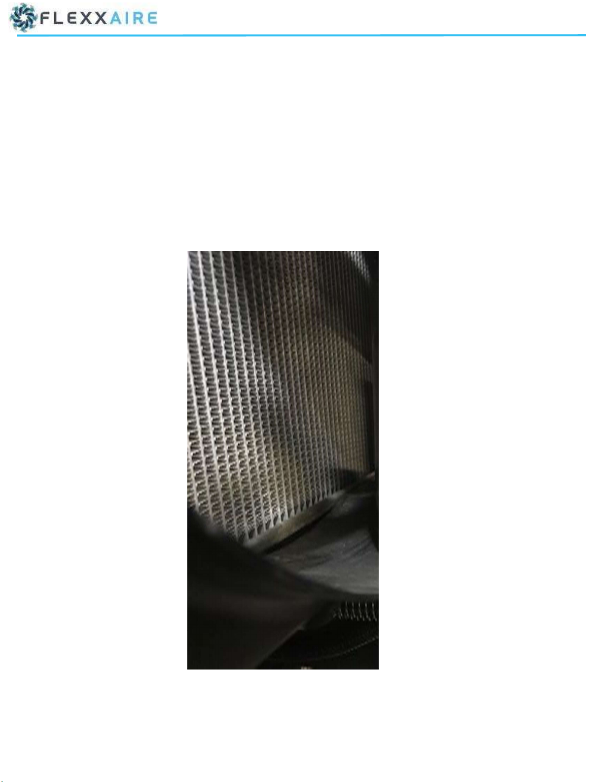
INSTRUCTIONS FOR REMOVAL OF OEM FAN
1. Open hood and remove engine access panels from both sides of the engine.
2. Remove items required to gain access to the fan. Items can include fan shroud, brackets, hoses, etc. If required, remove or adjust
hoses/tubing from sides of engine to expose the OEM fan. Cover hoses/tubing as required to prevent foreign debris from entering.
3. Remove OEM fan and spacer from pulley.
ENGINE ACCESS
PANELS
ENGINE ACCESS
PANELS
4
Follow installaon instrucons from Flexxaire as no addional modificaons are required for this applicaon
In addion to this manual (XXXXX) reference to the following documents is required for supplemental instrucons and safety
consideraons
Fan manual—document 02090
Control Kit manual—document 00732
Manual switch informaon and wiring on this manual supersedes the same informaon on document 00732
5
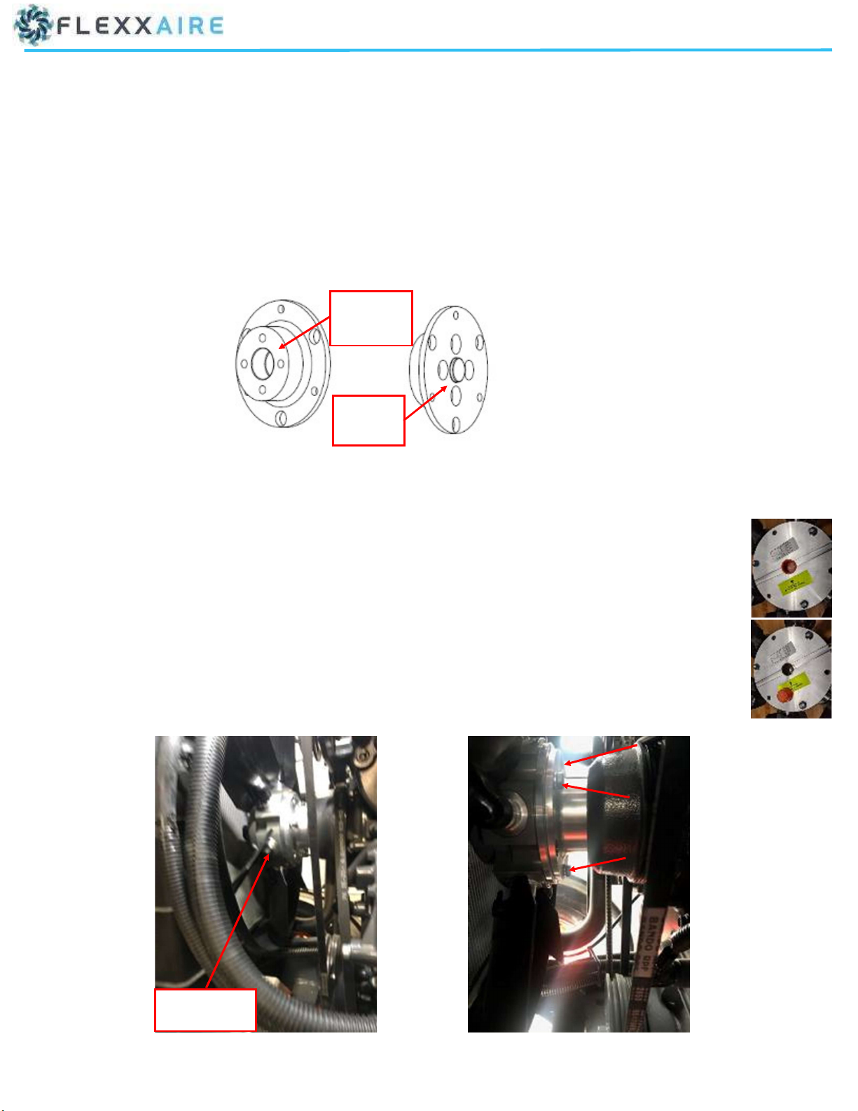
INSTRUCTIONS FOR ADAPTOR TO FAN DRIVE / FAN HUB INSTALLATION
** Requires mounng hardware that is different than stock OEM fan installaon. **
Flexxaire adapter/spacer to fan drive pulley.
1. Place the mounng adapter over the pulley studs.
2. Thread previously removed nuts (4) onto studs.
3. Follow original equipment manufacturer’s torque and thread locking specificaons when securing the mounng adapter to the fan
drive.
Flexxaire fan assembly to Flexxaire adapter.
4. Remove the shipping plug from the rear of the fan prior to bolng onto adapter. (see pictures to the right)
5. Locate (x3) bolts M8 x 1.25 x 30MM GR 10.9 (Flexxaire p/n 11875).
6. Place fan into engine compartment and finger-thread the 3 bolts to secure fan to mounng adapter.
7. If required, spin fan by turning alternator to make it easier to reach the bolts.
8. Torque the M8 bolts to 21 -lbs (28 N.m). Do not use Locte.
NOTE: Remove the shipping plug from the rear of the fan prior to bolng onto adapter
FRONT—
FAN SIDE
BACK -
PULLEY SIDE
FAN ASSEMBLY
6
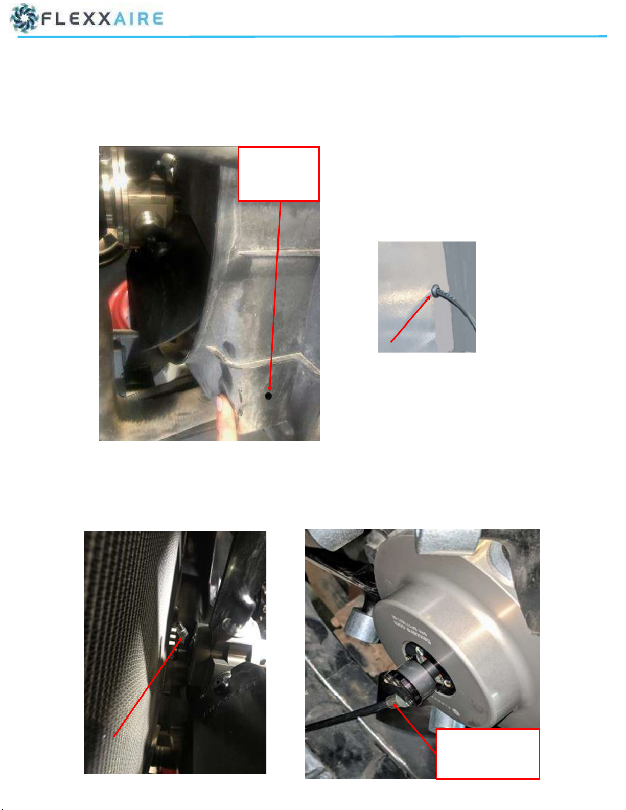
INSTRUCTIONS FOR AIRLINE INSTALLATION TO FAN
1. Drill a 15/32” hole on boom right corner of fan shroud for the supply airline and install the rubber grommet.
2. Insert airline through the grommet and leave approx. 24” scking into the fan shroud.
3. Connect airline to the push-in fing of rotary union on the fan.
4. Leave a slight curve (slack) in the airline between the rotary union and the grommet at the boom right corner of the shroud.
AIRLINE CONNECTION
TO ROTARY UNION
FITTING
BOTTOM RIGHT
CORNER OF FAN
SHROUD

7
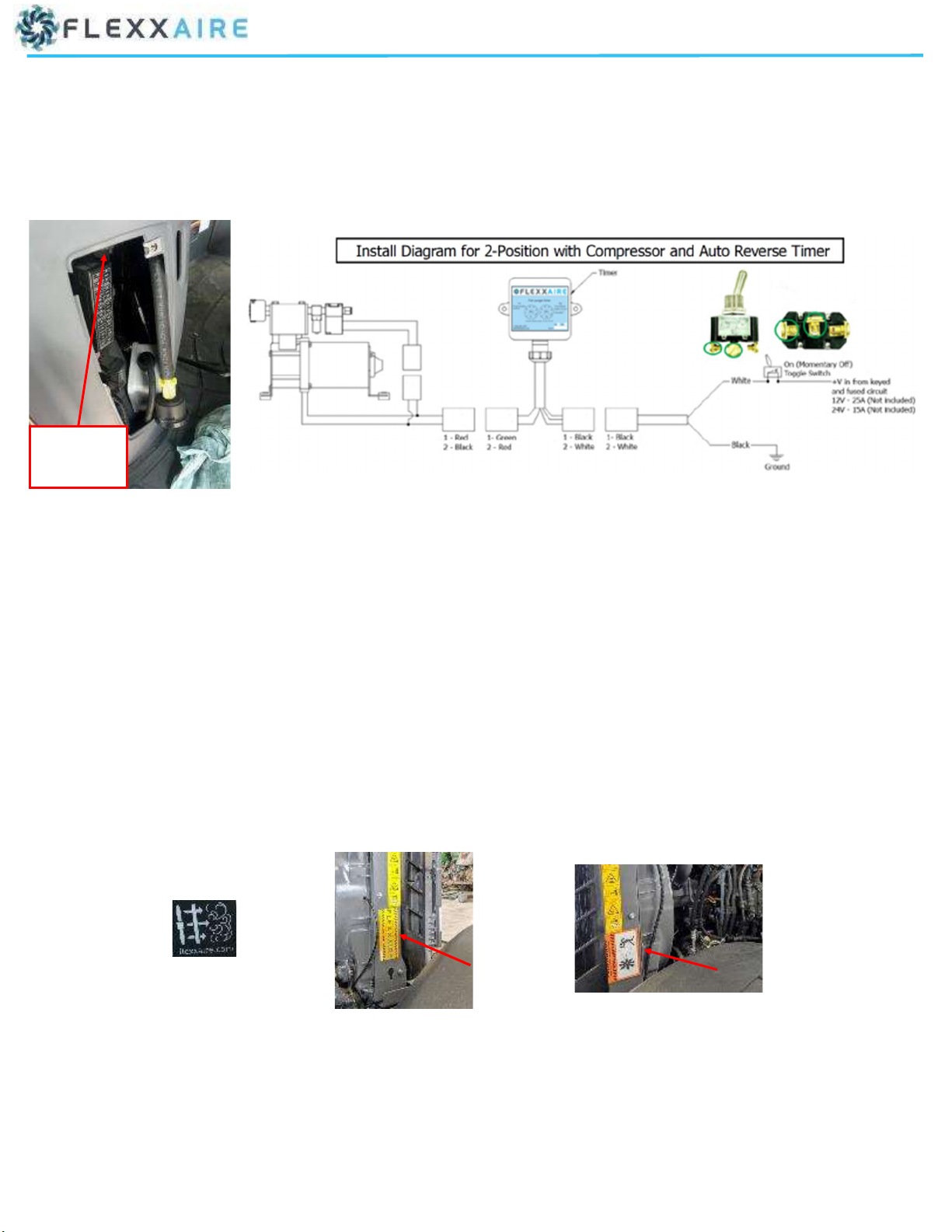
INSTRUCTIONS FOR COMPRESSOR INSTALLATION
1. Locate the cab access panel/port under the cab at front right.
2. Locate compressor / valve assembly and thread the ¼” fing into port 2 of the valve.
3. Remove airfilter from compressor .
4. Place compressor (upside down) under the floor of the cab next to access panel/port and mark hole locaons (x3) for mounng. Valve
should be facing towards rear of tractor.
5. Inside the cab, remove the console access panel, and if required li the flooring, on the right side; next to the door and at the console.
**Adjust/move any items that may be in the same locaon as the 3 marked hole locaons.
6. Drill (3x) holes and aach compressor under the floor of cab. Make sure to install the (3x) rubber grommets to reduce vibraon.
CAB ACCESS
PANEL/PORT
CAB ACCESS
PANEL/PORT
COMPRESSOR / VALVE ASSEMBLY
7. Thread elbow fing with male 1/4” NPT thread from airfilter relocaon kit into compressor filter port.
8. Aach airline from airfilter relocaon kit to fing and route hose into the right console in the cab through the access panel/port in the
floor.
COMPRESSOR / VALVE ASSEMBLY
MOUNTED UNDER CAB
ELBOW FITTING
AND AIRLINE
RIGHT CONSOLE ACCESS
PANEL REMOVED

8
INSTRUCTIONS FOR CONNECTIONS AND ROUTING OF AIRLINE
1. Route ¼” airline exing from the right boom of fan shroud along the frame and exisng lines to the push-in fing previously installed
on port 2 of the compressor valve.
NOTE: Secure airline from fan with zip es as required.
2. Cut-off excess ¼” airline.
3. Insert the ¼” airline from the fan into the push-in fing on the valve (port 2).
4. Install elbow fing with female 1/4” NPT thread from airfilter relocaon kit into the airfilter.
5. Install elbow fing with airfilter onto the airline previously routed into the console from the compressor.
AIRLINE FROM
COMPRESSOR
COMPRESSOR
FILTER

9
INSTRUCTIONS FOR ELECTRICAL CONNECTIONS BETWEEN TIMER, COMPRESSOR AND
POWER CABLE
1. From inside the cab, feed the wire lead with receptacle from the mer through the floor using the cab access panel/port inside the right
console.
2. Connect the receptacle from the mer to the plug on the compressor.
3. Locate the power cable (Cable, 18GA2 14’)
4. Connect the plug from the mer to the receptacle from the power cable.
5. Feed the power cable through the cab access panel/port to the inside of the right console.
NOTE: Secure power cable and mer wire lead with zip es as required.
TIMER ENCLOSURE BOX
WIRE LEAD FROM TIMER
RECEPTACLE FROM TIMER
TIMER ENCLOSURE
BOX
POWER CABLE
PLUG FROM TIMER

10
INSTRUCTIONS FOR CONNECTING THE POWER CABLE
1. Locate manual override toggle switch.
2. Locate blank accessory plate on console to the right of operator’s seat and remove it from console.
3. Place manual override switch on blank accessory plate to layout the hole locaon and drill a 1/2” hole.
4. Mount the manual override switch to the blank accessory plate.
5. Feed the power cable through the opening of the accessory blank plate on the console.
6. Leave approx. 12” of extra cable and cut-off excess.
7. Connect the white (power) wire of the power cable coming from the mer to 1 of 2 terminals on the back of the manual override
switch.
8. Connect the 25A inline fuse wire to 1 of 2 terminals on the back of the manual override switch.
NOTE: orientaon of the purge switch. Green circles in image below.
9. Mount the accessory plate with the manual override switch to the console.
BLANK ACCESSORY
PLATE
MANUAL OVERRIDE
TOGGLE SWITCH
BACK OF PURGE SWITCH
11
INSTRUCTIONS FOR ROUTING AND CONNECTING THE POWER CABLE
10. Connect the black (ground) wire from the power cable to the grounding stud next to fuse panel inside the console.
11. Locate a suitable source for keyed power at the fuse box. ex. radio, 12V plug, etc.
12. Tie-in and solder the 25A inline fuse into the keyed power source.
13. This completes the fan kit installaon.
NOTE: PRIOR TO TESTING
Reference back to universal manual 02090 to ensure all requirements are met before tesng.
14. Aer tesng and confirming the funconality of the fan, re-assemble the various parts. Ex. console panel, floor, engine access panels,
etc.
15. Apply various display and warning sckers to console and radiator/engine bay, as applicable.
GROUNDING
STUD

12
THANK YOU
FLEXXAIRE INC.
10430—180 STREET, EDMONTON, AB, CANADA
+1 780 483 3267
www.flexxaire.com
SALES
sales@flexxaire.com
+1-780-483-3267
TOLL FREE IN NORTH AMERICA
1-866-489-3267
SUPPORT
support@flexxaire.com
+1-780-483-3267
TOLL FREE IN NORTH AMERICA
1-866-489-3267
Table of contents
Other Flexxaire Fan manuals


