Flightcell MOP 00010 User manual

117-00020 Rev 4.0 Effective Date: 28 October 2022 Page 2 of 12
Section 1: Revisions & Approvals
Version
Date
Author
Change Note Number
Description
1.0
2nd November 2016
J. Glasgow
FCN0708
Initial release.
2.0
3rd January 2019
J. Glasgow
#HW516
Removed references to USB
and RS485.
3.0
19th August 2022
JJ Booyse
HW-2147
New release
4.0
28th October 2022
JJ Booyse
HW-2224
Removed Reset Reference
Except as expressly provided below, no part of this document may be reproduced, copied, transmitted, disseminated, downloaded, or
stored in any storage medium, for any purpose other than that which Flightcell International has provided this document for. Any
electronic or printed copy of this document or any revision must contain the complete text of this copyright notice. Any unauthorised
commercial distribution of this document or any revision hereto is strictly prohibited. Information in this document is subject to change.
Document users are responsible for ensuring printed copies are valid prior to use.
© Copyright 2022 Flightcell International Ltd –All Rights Reserved

117-00020 Rev 4.0 Effective Date: 28 October 2022 Page 3 of 12
CONTENTS
Section 1: Revisions & Approvals.................................................................................................... 2
Section 2: Introduction .................................................................................................................... 4
Section 3: Flightcell Iridium Modem Specifications.......................................................................... 5
Section 4: Components required for installation .............................................................................. 6
Connectors and fasteners ............................................................................................................ 6
Antenna ....................................................................................................................................... 6
Section 5: Installing the Flightcell Iridium modem............................................................................ 7
Mounting the modem ................................................................................................................... 7
Wiring the modem........................................................................................................................ 7
Guidelines for fabricating the wiring harness................................................................................ 8
Guidelines for the antenna cable.................................................................................................. 8
Section 6: Setting up your modem .................................................................................................. 9
Connecting to the Iridium network ................................................................................................ 9
Configuring your DZMx to work with the modem .......................................................................... 9
Using the Modem Standalone ...................................................................................................... 9
Installing a SIM card..................................................................................................................... 9
Section 7: Warranty and contact details ........................................................................................ 10
Limited warranty for your Flightcell Iridium Modem..................................................................... 10
Section 7: Documentation and Information.................................................................................... 11
Contact Details........................................................................................................................... 11
Mailing Address ...................................................................................................................... 11
Physical Address..................................................................................................................... 11
Appendix 1: Wiring and installation drawings ................................................................................ 12

117-00020 Rev 4.0 Effective Date: 28 October 2022 Page 4 of 12
Section 2: Introduction
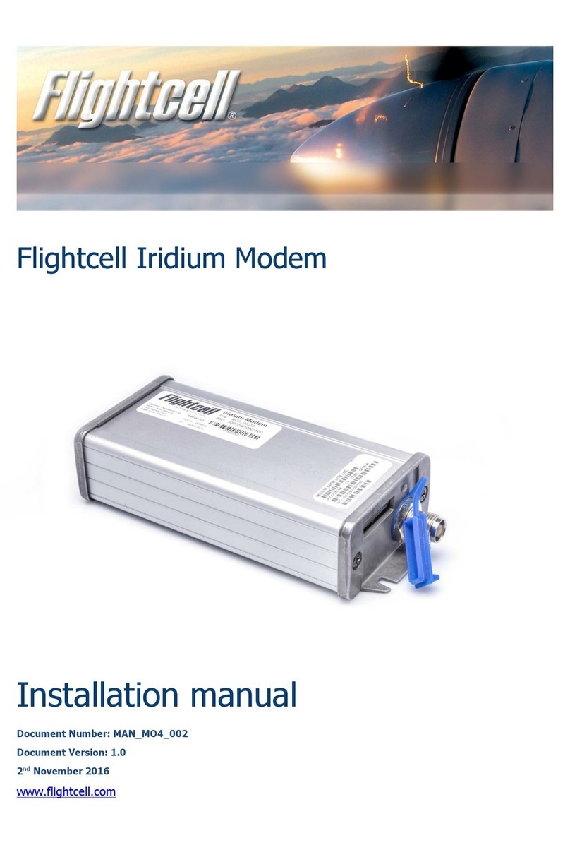
The Flightcell Iridium Modem is a robust modem designed specifically for installation with a DZMx
or as a standalone modem. The modem supports Iridium voice, SMS, SBD and data services.
If the modem is installed with a DZMx, the DZMx controls the modem and provides audio
integration into the aircraft ICS/audio panel.
The modem must be installed with an appropriate external Iridium antenna. Several antenna
options are available from Flightcell International.

117-00020 Rev 4.0 Effective Date: 28 October 2022 Page 5 of 12
Section 3: Flightcell Iridium Modem Specifications
Flightcell part number
MOP_00010
Material
Faceplate and backplate –diecast Type 380
Aluminium with Black Powder Coat finish
Extrusion –6063 Aluminium with clear
anodized finish
Input voltage
12-32 V DC
Power supply current
Maximum current –500mA @ 28V
RF Frequency Range
1616MHz –1624.5MHz
Average RF TX Power
During a TX slot
(max)
7W
During a frame (typ.)
0.6W
RF RX Sensitivity
-118dBm
Max cable loss1
3dB
Max Antenna gain
3dBi
MIC audio
Input
Fully Differential –50mVrms to 1Vrms
Nominal 775mVrms
Input impedance
600Ω
SPK audio
Output
Fully differential –Up to 1Vrms into 150 Ω
Nominal 775mVrms
Output impedance
600Ω
Data connection
RS-232 - RTS/CTS Flow control only.
Weight
240 grams
8.5 oz
Dimensions
Width
62mm
2.44”
Height
33.9mm
1.35”
Depth
144mm
5.67”
Main connector
DA-15F
Antenna connector
TNC
Certification
DO160G Sections: 20 RF Susceptibility), 21
(EMI)
The total implementation loss for antenna, connectors, cable and any other RF components between the modem and the
antenna should not exceed 3dB.

117-00020 Rev 4.0 Effective Date: 28 October 2022 Page 6 of 12
Section 4: Components required for installation
Connectors and fasteners
The modem is connected to a wiring harness which is in turn is connected to a Flightcell DZMx (or
a PC/embedded device).
Following are the terminating connectors and fasteners used with the modem.
Connectors
Main connector
M24308/4-2F (DA-15 Male)
Antenna connector
TNC
Fasteners
4 x M4 screws or bolts sized to fit mounting
surface
Antenna
The Flightcell Iridium Modem requires an antenna installed on the top of the aircraft, or in a location
with a clear view of the sky (for standalone installations), mounted as close to horizontal as
possible. The following should be considered when determining a mounting location on an
aircraft:
»Maintain good separation from other antennas. Preferred separation is 750mm from L-
band (GPS), TCAS or transponder antennas, but a lesser separation can be applied if
there is limited space on the aircraft.
»On a helicopter, the antenna can be installed below the rotor blades, but avoid installing it
close to the rotor hub, as the hub and inner rotor can block the antenna’s view of the sky.
»Keep coax cable lengths short to minimize attenuation of transmit and receive signals.
Iridium antenna cables must be selected to keep signal loss within accepted levels. Total signal
loss on the Iridium connection between the DZMx and the antenna should not exceed 3dB at
1645MHz.
Following are recommended Flightcell antennas. These can be used on an aircraft or stand alone.
These can be obtained from Flightcell International or your authorised Flightcell dealer.
Antenna
Application
Part number
Dual Flat Antenna L1 GPS/Iridium BNC/TNC
TSO Cert
Where both Iridium and
GPS are required
ANP_00043
Single Flat Antenna Iridium TNC White TSO
Cert
Iridium only
ANP_00045

117-00020 Rev 4.0 Effective Date: 28 October 2022 Page 7 of 12
Section 5: Installing the Flightcell Iridium modem
Mounting the modem
The modem should ideally be located close to the DZMx (if installed with DZMx), preferably where
it is reasonably readily accessible to enable easy access to the SIM card.
Appendix 2 includes drawing references for a dimensioned drawing of the modem, showing
mounting details.
Wiring the modem
The data and audio connections should be made as per the wiring diagrams referenced in
Appendix 1.
Modem pin
Function
1
DC in
Power
2
Audio from Sat Lo
Output
3
Audio to Sat Lo
Input
4
Ground
GND
5
RS-232 RTS
Input
6
RS-232 CTS
Output
7
Not used
-
8
Not used
-
9
Ground
Ground
10
Audio from Sat HI
Output
11
Audio to Sat HI
Input
12
Not used
-
13
RS-232 RXD
Input
14
RS-232 TXD
Output
15
Ring indicator
Output

117-00020 Rev 4.0 Effective Date: 28 October 2022 Page 8 of 12
Guidelines for fabricating the wiring harness
For aviation applications, all wiring should be carried out with aviation specification fireproof cable.
Screened cable should be used where indicated in the wiring diagrams. Where cable screen connections are
not explicitly shown, they should be left unterminated.
The following minimum wiring specification is recommended:
»Power supply - 22 AWG (0.325mm2)
»Other cabling - 24 AWG (0.205mm2).
Guidelines for the antenna cable
The antenna and associated cabling should have a nominal impedance of 50Ω with a maximum
attenuation of 3dB over the cable run. Following are the recommended cables specifications.
Cable Length
Cable Specification
Up to 3m
RG58C/U or RG400
Up to 6.5m
LMR200 or RG142A/U-9006 cell foil
Up to 8m
RG213
Up to 17m
LMR400
Up to 26m
LMR600

117-00020 Rev 4.0 Effective Date: 28 October 2022 Page 9 of 12
Section 6: Setting up your modem
Connecting to the Iridium network
The Flightcell Iridium modem operates on the Iridium satellite network. To enable connectivity an
Iridium SIM card provisioned for the desired services is required. The SIM can be obtained from
your preferred Iridium service provider.
Configuring your DZMx to work with the modem
Your DZMx will need to be configured to use the Flightcell Iridium Modem. Instructions for
configuring a DZMx to work with the modem can be found in the Installation Manual for the DZMx.
These manuals are available from the Flightcell support page at
https://www.flightcell.com/resources.
Using the Modem Standalone
If the modem is to be used in standalone mode it will need to be connected to a PC (or embedded
device) which can control the internal Iridium transceiver directly. The Iridium modem uses the
Iridium 9523 transceiver.
The modem provides analogue audio and RS232 data. For RS232 the default data rate is 19200
baud, 8 bits, 1 stop, no parity. RTS/CTS flow control is optionally available when using RS232.
The RS232 connects directly to the Iridium 9523 modem allowing operation through the use of AT
commands. See the Iridium ISU AT Command Reference for the full set of AT commands and
responses.
Installing a SIM card
The Flightcell Iridium Modem will not register on a network until a valid SIM card with a current
account is installed.
The DZMx will provide an error message if either there is no SIM card installed, or there is an
invalid SIM installed. Please see the Installation Manual for your DZMx for more details on error
messages.
If the modem is standalone, the connected device will need to interrogate the modem via the AT
interface to determine the SIM / network registration status.
To install the SIM card:
»Remove the rubber plug in the end of the modem.
»Insert the SIM card in the slot and press till it clicks into place.
»Reinsert the rubber plug.
The correct orientation of the SIM card is with the gold contacts down, and with the end of the card
with the diagonal cut-out inserted first. The SIM card will not fully insert in the wrong orientation.

117-00020 Rev 4.0 Effective Date: 28 October 2022 Page 10 of 12
Section 7: Warranty and contact details
Limited warranty for your Flightcell Iridium Modem
Flightcell International Ltd.’s quality products are proudly designed and manufactured to the
highest standards in New Zealand.
Your Flightcell Iridium Modem is warranted for one year from date of sale.
The warranty is void if any labels are removed or if it is determined that your modem has been:
»Connected to a power supply delivering more than 32 Volts.
»Connected with reverse polarity.
»Installed in direct contravention to the guidelines outlined in the installation manual.
»Physically damaged, or a fault has occurred due to the product being used beyond what is
considered normal use, causing unusual deterioration of the product.
If the product is deemed to be faulty or in need of repair, please contact Flightcell International Ltd
to obtain a Returned Materials Authorization or download from https://www.flightcell.com/support

117-00020 Rev 4.0 Effective Date: 28 October 2022 Page 11 of 12
Section 7: Documentation and Information
Comprehensive documentation for the Flightcell Iridium Modem is available on the Flightcell
website http://www.flightcell.com/resources.
Contact Details
Mailing Address
Flightcell International Limited
PO Box 1481
Nelson 7040 New Zealand
Physical Address
Flightcell International Limited
98 Vickerman Street
Nelson 7010 New Zealand
Telephone +64 3 545 8651
Fax +64 3 548 8091
Email info@flightcell.com
Website http://www.flightcell.com

117-00020 Rev 4.0 Effective Date: 28 October 2022 Page 12 of 12
Appendix 1: Wiring and installation drawings
Wiring diagrams and mechanical drawings are available on the Flightcell website
https://www.flightcell.com/resources.
Interconnect drawings for DZMx & Standalone installations:
»114-00021 –Flightcell Iridium Satellite Modem DZMx interconnect drawing
»114-00022 –Flightcell Iridium Satellite Modem standalone interconnect drawing
Mechanical drawings:
»115-00013 –Flightcell Iridium Satellite Modem General Arrangement Drawing
Table of contents
Other Flightcell Modem manuals

