Flintec FT-111 Series User manual
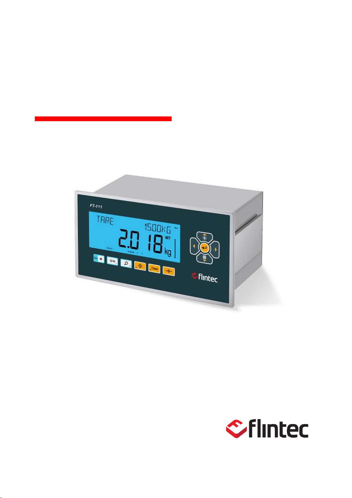
FT-111(D) Panel
Weighing Terminal
Technical Manual

FT-111(D) Panel Weighing Indicator, Technical Manual, Rev.1.0.0, May 2019 Page 1of 146
Table of Contents:
1Safety Instructions ..................................................................5
2Declaration of Conformity .......................................................6
3Introduction .............................................................................7
3.1 Overview .............................................................................................................................................7
3.2 Variants...............................................................................................................................................7
3.3 Specifications......................................................................................................................................8
3.4 The Front View and Key Functions...................................................................................................13
Display...............................................................................................................................................13
3.5 Key Pad.............................................................................................................................................15
3.6 Passwords.........................................................................................................................................16
Key lock.............................................................................................................................................16
Passwords.........................................................................................................................................16
4Installation.............................................................................17
4.1 Recommendations ............................................................................................................................17
Environment......................................................................................................................................17
Cabling..............................................................................................................................................17
Electrical Connection ........................................................................................................................17
Location of the Peripheral Connections............................................................................................18
4.2 Cleaning............................................................................................................................................18
4.3 Disposal.............................................................................................................................................18
4.4 Housing.............................................................................................................................................19
4.5 Mechanical Installation......................................................................................................................19
4.6 Electrical Connections.......................................................................................................................20
Analogue Load Cell Connection (Only FT-111)................................................................................20
Digital Load Cell Connection (Only FT-111 D)..................................................................................21
RS232C Serial Port...........................................................................................................................22
RS485 Serial Port .............................................................................................................................23
RS422 Serial Port .............................................................................................................................24
Ethernet TCP/IP................................................................................................................................25
Profibus DP.......................................................................................................................................26
Profinet..............................................................................................................................................26
CANopn.............................................................................................................................................27
EtherNET/IP......................................................................................................................................28
EtherCAT...........................................................................................................................................29
CC-Link .............................................................................................................................................29
Powerlink...........................................................................................................................................30
CC-Link IE.........................................................................................................................................30
USB Port ...........................................................................................................................................31
Installation of Alibi SD card ...............................................................................................................31
Installation of SD Card ......................................................................................................................32
Digital Inputs:.....................................................................................................................................33
Digital Outputs:..................................................................................................................................33
Analogue Connection........................................................................................................................34
Power Source Connection and Grounding .......................................................................................34
5FT-111(D) Functions.............................................................35
5.1 Basic Functions.................................................................................................................................35
5.2 Advanced Functions..........................................................................................................................37
5.3 Alibi Memory......................................................................................................................................39
6Programming and Calibration ...............................................41
6.1 Entering to the Programming and Calibration...................................................................................41
6.2 Quick Access Parameter Blocks used Frequently............................................................................42
6.3 Exit from Programming .....................................................................................................................42
6.4 Programming and Parameters..........................................................................................................43
6.5 Calibration.........................................................................................................................................67

FT-111(D) Panel Weighing Indicator, Technical Manual, Rev.1.0.0, May 2019 Page 2of 146
Linearity Correction...........................................................................................................................67
Zero and Span Adjustments..............................................................................................................68
eCal Electronic Calibration...............................................................................................................69
Gravity adjustment ............................................................................................................................70
Calibration coefficients......................................................................................................................70
7Digital Load Cell (DLC) .........................................................71
7.1 Addressing Digital Load cells............................................................................................................71
8Digital inputs and outputs......................................................73
8.1 Digital inputs......................................................................................................................................74
8.2 Digital outputs....................................................................................................................................75
9Serial Data Outputs...............................................................85
9.1 Continuous Data Output....................................................................................................................85
Continuous Data Formats.................................................................................................................86
9.2 Fast Continuous Data Output............................................................................................................89
9.3 Print Mode.........................................................................................................................................89
9.4 EPL Format.......................................................................................................................................90
9.5 BSI Data Structure for Dialog with PC ..............................................................................................91
BSI-Base Commands........................................................................................................................93
10 Optional Communication.......................................................96
10.1 Analogue Output ...............................................................................................................................96
10.2 Modbus RTU and TCP/IP .................................................................................................................97
Modbus Command Table;.................................................................................................................98
10.3 Ethernet TCP/IP..............................................................................................................................104
Ethernet Parameters.......................................................................................................................104
10.4 Profibus DP.....................................................................................................................................105
Data Format ....................................................................................................................................105
GSD Configuration..........................................................................................................................106
Profibus DP Data Structure.............................................................................................................106
10.5 Profinet............................................................................................................................................107
Data Format ....................................................................................................................................108
Profinet Parameters ........................................................................................................................108
GSDML Configuration.....................................................................................................................108
Profinet Data Structure....................................................................................................................109
10.7 CANopen.........................................................................................................................................110
Data Format ....................................................................................................................................110
EDS Configuration ..........................................................................................................................111
CANopen Date Structure ................................................................................................................111
10.8 EtherNet/IP......................................................................................................................................112
Data Format ....................................................................................................................................113
EtherNet/IP Parameters..................................................................................................................113
EDS Configuration ..........................................................................................................................113
EtherNet/IP Data Structure .............................................................................................................114
10.9 EtherCAT.........................................................................................................................................115
Data Format ....................................................................................................................................115
ESI Configuration............................................................................................................................116
EtherCAT Data Structure ................................................................................................................116
10.10 CC-Link ...........................................................................................................................................117
Data Format ....................................................................................................................................117
CC-Link Configuration.....................................................................................................................118
CC-Link Data Structure...................................................................................................................118
10.11 Powerlink.........................................................................................................................................119
Data Format ....................................................................................................................................120
XDD Configuration ..........................................................................................................................120
Powerlink Data Structure ................................................................................................................120
10.12 CC-Link IE Field..............................................................................................................................121
Data Format ....................................................................................................................................121
CC-Link IE Configuration ................................................................................................................122
CC-Link IE Data Structure...............................................................................................................122

FT-111(D) Panel Weighing Indicator, Technical Manual, Rev.1.0.0, May 2019 Page 3of 146
11 Appendix 1: Data Structure Profibus, Profinet, EtherNET/IP,
EtherCAT, CC-Link, Powerlink, CC-Link IE..................................123
12 Appendix 2: Data Structure CANopen ................................132
13 Sealing of Approved Scale..................................................141
14 Trouble Shooting.................................................................142

FT-111(D) Panel Weighing Indicator, Technical Manual, Rev.1.0.0, May 2019 Page 4of 146
RIGHTS AND LIABILITIES
All rights reserved.
No part of this publication may be reproduced, stored in a retrieval system, or transmitted in any form or
by any means, mechanical, photocopying, recording, or otherwise, without the prior written permission of FLINTEC
GmbH.
No patent liability is assumed with respect to the use of the information contained herein. While every precaution has
been taken in the preparation of this book, FLINTEC GmbH assumes no responsibility for
errors or omissions. Neither is any liability assumed for damages resulting from the use of the information contained
herein.
The information herein is believed to be both accurate and reliable. FLINTEC GmbH, however, would be obliged to be
informed if any errors occur. FLINTEC GmbH cannot accept any liability for direct or indirect damages resulting from
the use of this manual.
FLINTEC GmbH reserves the right to revise this manual and alter its content without notification at any
time.
Neither FLINTEC GmbH nor its affiliates shall be liable to the purchaser of this product or third parties for damages,
losses, costs, or expenses incurred by purchaser or third parties as a result of: accident,
misuse, or abuse of this product or unauthorized modifications, repairs, or alterations to this product,
or failure to strictly comply with FLINTEC GmbH operating and maintenance instructions.
FLINTEC GmbH shall not be liable against any damages or problems arising from the use of any options
or any consumable products other than those designated as Original FLINTEC GmbH Products.
NOTICE: The contents of this manual are subject to change without notice.
Copyright © 2016 by FLINTEC GmbH; 74925 Meckesheim, Bemannsbruch 9, Germany

FT-111(D) Panel Weighing Indicator, Technical Manual, Rev.1.0.0, May 2019 Page 5of 146
1 SAFETY INSTRUCTIONS
CAUTION! READ THIS MANUAL BEFORE OPERATING OR SERVICING THIS
EQUIPMENT. FOLLOW THESE INSTRUCTIONS CAREFULLY. SAVE THIS MANUAL
FOR FUTURE REFERENCE.DO NOT ALLOW UNTRAINED PERSONNEL TO OPERATE,
CLEAN, INSPECT, MAINTAIN, SERVICE, OR TAMPER WITH THIS EQUIPMENT.
ALWAYS DISCONNECT THIS EQUIPMENT FROM THE POWER SOURCE BEFORE
CLEANING OR PERFORMING MAINTENANCE. CALL FLINTEC ENGINEERING FOR
PARTS, INFORMATION, AND SERVICE.
WARNING! ONLY PERMIT QUALIFIED PERSONNEL TO SERVICE THIS EQUIPMENT.
EXERCISE CARE WHEN MAKING CHECKS, TESTS AND ADJUSTMENTS THAT MUST
BE MADE WITH POWER ON. FAILING TO OBSERVE THESE PRECAUTIONS CAN
RESULT IN BODILY HARM.
WARNING! FOR CONTINUED PROTECTION AGAINST SHOCK HAZARD CONNECT TO
PROPERLY GROUNDED OUTLET ONLY. DO NOT REMOVE THE GROUND PRONG.
WARNING! DISCONNECT ALL POWER TO THIS UNIT BEFORE REMOVING ANY
CONNECTION, OPENING THE ENCLOSURE OR SERVICING.
WARNING! BEFORE CONNECTING/DISCONNECTING ANY INTERNAL ELECTRONIC
COMPONENTS OR INTERCONNECTING WIRING BETWEEN ELECTRONIC
EQUIPMENT ALWAYS REMOVE POWER AND WAIT AT LEAST THIRTY(30) SECONDS
BEFORE ANY CONNECTIONS OR DISCONNECTIONS ARE MADE. FAILURE TO
OBSERVE THESE PRECAUTIONS COULD RESULT IN DAMAGE TO OR
DESTRUCTION OF THE EQUIPMENT OR BODILY HARM.
CAUTION! OBSERVE PRECAUTIONS FOR HANDLING ELECTROSTATIC SENSITIVE
DEVICES.

FT-111(D) Panel Weighing Indicator, Technical Manual, Rev.1.0.0, May 2019 Page 6of 146
2 DECLARATION OF CONFORMITY
EU-Konformitätserklärung
EU-Declaration of Conformity
Monat/Jahr: month/year:
07/2019
Hersteller: Manufacturer:
Flintec GmbH
Anschrift: Address:
Bemannsbruch 9
D-74909Meckesheim
Deutschland/Germany
Produktbezeichnung:Product name:
Nr. der Bauartzulassung:
No oft the EC type-examination certificate:
Nichtselbsttätige Waage (NSW)
Non-automatic Weighing Instrument (NAWI)
FT-11x / FT 11x panel Wägeterminal / Weighing
Terminal
No. 0200-NAWI-04810, FORCE Certification
Das bezeichnete Produkt stimmt mit folgenden Vorschriften der Europäischen Richtlinien überein:
This product confirms with the following regulations of the Directives of the European Community
Richtlinie 2014/35/EU Niederspannungs-Richtlinie
Richtlinie 2014/30/EU EMV
Richtlinie 2011/65/EU RoHS
Richtlinie 2014/31/EU Nichtselbsttätige Waagen
Directive2014/35/EULowVoltage Directive
Directive2014/30/EUElectromagneticcompatibility
Directive2011/65/EURoHS
Dircetive2014/31/EUNon-AutomaticWeighing
Die Absicherung aller produktspezifischen
Qualitätsmerkmale erfolgt auf Basis eines
zertifizierten Qualitätsmanagement-Systems nach
DIN ISO 9001.
All product-related features are assured by a quality
system in accordance with ISO 9001.
FolgendeNormenwerdenzumNachweisderÜbereinstimmungmitdenRichtlinieneingehalten:
Asaproofofconformitywiththedirectivesfollowingstandardsarefulfilled:
EN 60950-1:2008
EN 61326-1:2013
EN 50581:2012
EN 45501:2015
DieseErklärungbescheinigtdieÜbereinstimmung
mitdengenanntenRichtlinien,beinhaltetjedoch
keineZusicherungvonEigenschaften.
Thisdeclarationcertifiestheconformitywiththelisted
directives,butitisnopromiseofcharacteristics.

FT-111(D) Panel Weighing Indicator, Technical Manual, Rev.1.0.0, May 2019 Page 7of 146
3 INTRODUCTION
3.1 Overview
FT-111 Weighing indicator is economic and powerful state-of-the-art indicator for industrial weighing applications like basic
weighing, labelling system control with digital outputs, fieldbus interfacing etc. It’s set memory 500 item record size which
each item has 5 pieces limit values gives big advantage in operation.
Digital inputs and outputs of the instrument can be programmed as a Remote IO on the fieldbus. This feature gives
advantage to eliminate additional PLC in the cabinet for only having remote IO’s.
The scales equipped with FT-111 weighing indicator can be used in all kind of industrial areas up harsh, to wet and hygienic
environments with its fast and efficient cleaning that was designed and built according to the international guidelines.
3.2 Variants
These panel type indicators may have various industrial interfacings and digital Inputs/Outputs. A variant of FT-
111 (D) indicators specifies the peripheral interfacings of the instrument as shown below. All variants can
connect to Modbus RTU and Modbus TCP instruments which requirements Modbus SD card.
Other features and specifications of all variants are the same. FT-111 (D) names are used as family names in
this manual. Variant names are written only to describe interfacing the instrument have.
FT-111
FT-111 D
FT-111 IO
FT-111 D IO
FT-111 AN
FT-111 D AN
FT-111 PB
FT-111 D PB
FT-111 PN
FT-111 D PN
FT-111 CO
FT-111 D CO
FT-111 EI
FT-111 D EI
FT-111 EC
FT-111 D EC
FT-111 CC
FT-111 D CC
FT-111 PL
FT-111 D PL
FT-111 IE
FT-111 D IE
Serial interface RS 232C
Yes
Yes
Yes
Yes
Yes
Yes
Yes
Yes
Yes
Yes
Yes
Serial interface RS 485
Yes
Yes
Yes
Yes
Yes
Yes
Yes
Yes
Yes
Yes
Yes
Serial interface RS 422
Yes
Yes
Yes
Yes
Yes
Yes
Yes
Yes
Yes
Yes
Yes
USB
Yes
Yes
Yes
Yes
Yes
Yes
Yes
Yes
Yes
Yes
Yes
Digital 4 Input / 5 Output
-
Yes
Yes
Yes
Yes
Yes
Yes
Yes
Yes
Yes
Yes
Analogue output
-
-
Yes
-
-
-
-
-
-
-
-
Profibus DPV1
interface
-
-
-
Yes
-
-
-
-
-
-
-
CANopen interface
-
-
-
-
-
Yes
-
-
-
-
-
CC-Link interface
-
-
-
-
-
-
-
-
Yes
-
-
Profinet interface
-
-
-
-
Yes
-
-
-
-
-
-
Ethernet interface
Yes
Yes
Yes
Yes
Yes
Yes
Yes
Yes
Yes
Yes
Yes
EtherNet/IP interface
-
-
-
-
-
-
Yes
-
-
-
-
EtherCAT interface
-
-
-
-
-
-
-
Yes
-
-
-
Powerlink interface
-
-
-
-
-
-
-
-
-
Yes
-
CC-Link IE Field
-
-
-
-
-
-
-
-
-
-
Yes
Modbus RTU (optional)
Yes
Yes
Yes
Yes
Yes
Yes
Yes
Yes
Yes
Yes
Yes
Modbus TCP (optional)
Yes
Yes
Yes
Yes
Yes
Yes
Yes
Yes
Yes
Yes
Yes

FT-111(D) Panel Weighing Indicator, Technical Manual, Rev.1.0.0, May 2019 Page 8of 146
3.3 Specifications
Analogue Load cell (only FT-111)
A/D converter type
24-bit Delta-Sigma ratio metric with integral analog and digital filters
Conversion rate
Up to 1600 measurement values per second
Input sensitivity
0,4 μV/e approved; 0.05 μV/d non approved.
Analog input range
-5 mV to +19 mV
Internal resolution
up to 16 000 000
Excitation
5 VDC max. 150 mA
Number of load cells
Up to 8 load cells 350 Ω or 25 load cells 1100 Ω.
Connection
4- or 6-wire technique.
Home run cable length: maximum 1000 m/mm² for 6-wire connection between
FT-111 and junction box.
Digital load cell (only FT-111 D)
Interface
RS 485
Interface baud rate
Up to 57600
Connection
4 wire. Up to 500 meters.
Number of load cell
Up to 24 digital load cells.
Internal resolution
200 000 counts
Excitation
12 VDC, max. 1.3 A
Scale
Range
Single range, up to 3 x multi intervals, up to 3 x multi ranges.
Display resolution
FT-111 Approval, up to 10 000 division at usage in trade, according to EN45501
and OIML R76.
Up to 300 000 division at industrial usage.
FT-111 D Maximum 20 000 . Should be limited by 10% of the maximum count of
the digital load cell for accurate measurement.
Calibration and Functions
Calibration
Calibration with test weights,
eCal electronic calibration without test weights,
Temporary zero calibration,
Zero adjustment, Gain adjustment,
Coefficient entry.
Digital filter
5 steps programmable adaptive filter
Dynamic filter
Programmable dynamic filter
Weighing functions
Taring, zeroing, auto zero tracking, motion detection, auto zero at power up, tare
status save at power off, increased resolution, automatic tare and clear,
temporary gross indication, unit change.
Standard applications
Labelling with barcode, livestock weighing and free setpoints, basic peak, hold,
functional outputs, Remote IO of PLC or HMI, fieldbus interface.

FT-111(D) Panel Weighing Indicator, Technical Manual, Rev.1.0.0, May 2019 Page 9of 146
RS 422
Baud rate
1200 to 57600 programmable
Data
Length 7 or 8 bits; parity even, odd or none
Stations
Up to10 stations
Ethernet TCP/IP
Transmission rate
10 / 100 Mbit/s, Full duplex
TCP/IP settings
Manual IP assign over Indface2x PC Software or by keys in programming mode
Connection method
Server or Client
Installation
Switched Ethernet transmission with shielded twisted pair cables and RJ-45.
Isolation
Galvanically isolated bus electronics
Response speed
Up to 4 ms response delay after read/write commands
USB
Connection
Standard USB Micro-B cable
Response speed
Min. 4 ms response delay after read/write commands
Digital Inputs and Outputs (opional)
Digital Inputs
Optoisolated 4 digital input, 12 to 28 VDC, 10mA.
Any input(s) can be used as a Remote input of your PLC over BSI or Modbus.
Digital Outputs
5 free relay contact, 250 VAC or 30 VDC, 0.2A
Any output(s) can be used as a Remote output of your PLC over BSI or Modbus.
Analogue Output (opional)
Voltage output
0-5 VDC, 0-10 VDC
Current output
4-20mA, 0-20mA
Resolution
60 000 steps
Max. cable length
300 meters
Max. load resistance
(current output)
500 Ω
Minimum load
resistance (voltage
output)
10 kΩ
Memory
Application memories
Set Memory to save limit values at your industrial weighing.
Memory size is 500 item records
Alibi memory (optional)
99 999 records
Communication
Connectable with
PC, PLC, Printer, Remote display, EPL printer etc.
RS 232
Isolation
Galvanically isolated.
Baud rate
1200 to 57600 programmable
Data
Length 7 or 8 bits; parity even, odd or none
RS 485
Isolation
Galvanically isolated.
Baud rate
1200 to 57600 programmable
Data
Length 7 or 8 bits; parity even, odd or none
Stations
Up to 31 stations

FT-111(D) Panel Weighing Indicator, Technical Manual, Rev.1.0.0, May 2019 Page 10 of 146
Profibus DPV1 (opional))
Data rate
Up to 12000 kbit/s with automatic baud rate detection
GSD file
Generic GSD-file provided
Topology
Depending on physical media
RS-485: segmented line topology without stubs
Installations
Shielded twisted pair cable
Line length depending on physical media and transmission speed
Max. Stations
up to 126 stations per network
Isolation
Galvanically isolated bus electronics
Response speed
Min. 4 ms response delay after read/write commands
Remote IO
Digital inputs and outputs of the instrument can be programmed independently as
a Remote IO’s of PLC to control them over fieldbus.
Profinet (opional)
Data rate
100 Mbit/s, full duplex
GSDML file
Generic GSDML-file provided
TCP/IP settings
DHCP or manual IP are assigned over EtherX PC Software or by keys in
programming mode. Device identity customization
Topology
Line, Bus, Star or Tree topology depending on physical media
Installation
Switched Ethernet transmission with shielded twisted pair cables and RJ-45
connectors.
Web client
Available
Isolation
Galvanically isolated bus electronics
Response speed
Min. 4 ms response delay after read/write commands
Remote IO
Digital inputs and outputs of the instrument can be programmed independently as
a Remote IO’s of PLC to control them over fieldbus.
CANopen (opional))
Data rate
10 kbit/s –1 Mbit/s (selectable) kbit/s
EDS file
Generic EDS-file provided
Topology
Line with Trunkline, Dropline structure and Termination at both Ends
Line length depending on baud rate 25 –500 meter.
Installation
2 wire shielded twisted pair cable
Alternatively 4 wire with 24 Volt power over the bus
Max. Stations
Up to 127 stations per network
Isolation
Galvanically isolated bus electronics
Response speed
Min. 4 ms response delay after read/write commands
Remote IO
Digital inputs and outputs of the instrument can be programmed independently as
a Remote IO’s of PLC to control them over fieldbus.

FT-111(D) Panel Weighing Indicator, Technical Manual, Rev.1.0.0, May 2019 Page 11 of 146
EtherNet/IP (opional))
Data rate
10 Mbit/s or 100 Mbit/s, full duplex
EDS file
Generic EDS-file provided
DLR (Device Level
Ring)
Available
TCP/IP settings
DHCP or manual IP assign over EtherX PC Software or by keys in programming
mode.
Device identity customization
Topology
Line, Bus, Star or Tree topology depending on physical media
Installation
Switched Ethernet transmission with shielded twisted pair cables and RJ-45
connectors.
Web client
Available
Isolation
Galvanically isolated bus electronics
Response speed
Up to 4 ms. response delay after read/write commands.
Remote IO
Digital inputs and outputs of the instrument can be programmed independently as
a Remote IO’s of PLC to control them over fieldbus.
EtherCAT (opional)
Data rate
100 Mbit/s, full duplex
ESI file
Generic ESI-file provided
Topology
Line, Tree, Star or Daisy-chain topology depending on physical media
Installation
Switched Ethernet transmission with shielded twisted pair cables and RJ-45
connectors.
Isolation
Galvanically isolated bus electronics
Response speed
Up to 4 ms. response delay after read/write commands.
Remote IO
Digital inputs and outputs of the instrument can be programmed independently as
a Remote IO’s of PLC to control them over fieldbus.
CC-Link (opional)
Data rate
156 kbit/s –10 Mbit/s (selectable)
Topology
Line with Trunkline, Branch structure and Termination at both Ends.
Installation
3 wires shielded twisted pair cable.
Max. Stations
Up to 64 stations per network
Isolation
Galvanically isolated bus electronics
Response speed
Up to 4 ms. response delay after read/write commands
Remote IO
Digital inputs and outputs of the instrument can be programmed independently as
a Remote IO’s of PLC to control them over fieldbus.
Powerlink (opional)
Compatibility
Supports Ethernet POWERLINK V2.0 Communication Profile Specification
version 1.2.0
Data rate
100 Mbit/s, half duplex

FT-111(D) Panel Weighing Indicator, Technical Manual, Rev.1.0.0, May 2019 Page 12 of 146
XDD file
XDD-file provided
Ring redundancy
Available
Topology
100% free choice of star, tree, ring or daisy chain
Installation
Switched Ethernet transmission with shielded twisted pair cables and RJ-45
connectors.
Isolation
Galvanically isolated bus electronics
Response speed
Min. 4 ms response delay after read/write commands
Remote IO
Digital inputs and outputs of the instrument can be programmed independently as
a Remote IO’s of PLC to control them over fieldbus.
CC-Link IE Field (opional)
Data rate
1 Gbit/s Baud Rate
CSP+ file
Generic CSP+ file provided
Topology
Line, Star, Line/Star mixture or Ring topology depending on physical media
Installation
IEEE802.3 1000Base-T cable, ANSI/TIA/EIA-568-B (Category 5e) compliant 4-
pair
balanced-type shield cable, Double-shield type is recommended.
Max. number of
networks
Up to 239
Number of connected
nodes per network
Master station=1, Slave station= 120
Isolation
Galvanically isolated bus electronics
Response speed
Up to 4 ms. response delay after read/write commands.
Remote IO
Digital inputs and outputs of the instrument can be programmed independently as
a Remote IO’s of PLC to control them over fieldbus.
Power Consumption
FT-111
12 –28 VDC 250 mA + max. 500 mA for fieldbus interfacing
FT-111 D
12 –28 VDC 150 mA + max. 500 mA for fieldbus interfacing
+ load cell currents.
Environment and Enclosure:
Operation temp. range
Approved scales -10 °C to +40 °C
Industrial usage -15 °C to +55 °C
Humidity
80% RH max, non-condensing
Enclosure
Stainless steel front panel and rear panel, aluminum body.
Protection
Front panel IP67
Panel cut size
186 x 92 mm
(7.32 x 3.62”)
Sizes ( W x H x D )
205 x 108 x
112,5mm
(8.07 x 4.25 x 4.43”)
Weight
1,4 kg
(3,07 lb)
Packing sizes (W x H x
D)
273 x 190 x 153 mm
(10,75 x 7,48 x 6,02”)
Weight Packed
2,5 kg
(5,51 lb)

FT-111(D) Panel Weighing Indicator, Technical Manual, Rev.1.0.0, May 2019 Page 13 of 146
3.4 The Front View and Key Functions
Figure 3.1 –Front view of FT-111
Display
The bright and wide angle LCD display of the FT-111 instruments is shown below.
The meanings of the announcement symbols on the display are:
1
6-digit 22 mm height big weighing display with sign
2
16-digit 8 mm height alphanumeric information display
3
High resolution digit separator.
4
Announces the indicated value is the net weight.
5
Announces the indicated value is the gross weight.
1
3
4
5
6
2
7
8
9
10
11
12
13
14

FT-111(D) Panel Weighing Indicator, Technical Manual, Rev.1.0.0, May 2019 Page 14 of 146
6
Bar graph
7
Indicates the range of the scale at multi range and multi interval
operations.
8
g, kg, t, lb, klb, N, kN units are located on the right of the display.
9
Announces the activated inputs and outputs.
10
Announces the instrument is at repair status or call service.
11
Announces the weight value is in the center of zero range.
12
Announces the weighing is not stable. After stabilization of the
weighing, this symbol disappears.
13
Announces the keys are locked.
14
ms
Announces the time unit of the parameter value is millisecond or
second.

FT-111(D) Panel Weighing Indicator, Technical Manual, Rev.1.0.0, May 2019 Page 15 of 146
3.5 Key Pad
The keys and the key functions of FT-111 in usage are:
Programmable Function key This programmable key is set for your easy
usage in your application.
Escape Press this key to exit from any entry or from any block at programming.
Page 56, 37,
Temporary gross weight indication Press the key to read the gross weight
temporary until pressing the key.
The display returns to the normal operation automatically after 10 seconds at
approved scales.
High resolution Press the key to read the weight at high resolution. Press the
second time to return normal operation. The high resolution weight displaying is
ended automatically in 10 seconds at approved scales.
Page 37, 60
Set point entries Press this key to enter set points.
Page 84,
Memory This key is used to access the memory or to save the item
data in to the memory.
Page 84
Navigation keys These keys are used to navigate in the memories, entries and
programming.
The meanings of the navigation keys are;
Page 96
Previous parameter.
Next digit or parameter.
Increase or next block.
Decrease or previous block.
Enter into the parameter to enter data.
Save the data after entry.
Go to the next parameter.
Print By pressing this key the weight data is transferred to a printer or to a PC at
weighing.
Page 96, 89
Tare Press this key for taring the scale.
Page 35, 36, 55
Clear Clears the tare and indication returns to the gross value.
Page 36
Zeroing If the unloaded scale doesn’t show zero at gross operation, press this
key to compensate zero drift.
Page 35, 61

FT-111(D) Panel Weighing Indicator, Technical Manual, Rev.1.0.0, May 2019 Page 16 of 146
3.6 Passwords
RELATED PARAMETERS: Sub-block 26- .
Key lock
FT-111 has capability to lock the keys to avoid unauthorized interfere. The key(s) which would be locked are programmed in
the setup at sub-block 34- . Key lock password default is 11.
Lock the keys:
1. Press key for more than 2 seconds. [PASSWORD: ] prompt appears on the display.
2. Press key.
3. Press key. symbol appears on the display.
Unlock the keys:
1. Press key for more than 2 seconds. [PASSWORD: ] prompt appears on the display.
2. Press key.
3. Press key. symbol disappears on the display.
Passwords
User password
This password is used to setup the interface, usage configuration and application related parameters for
your application.
To enter the programing;
Display
Operation
[123.456 kg]
Press key until [ PASSWORD : ] prompts seen.
[PASSWORD]
+ + keys sequentially for user entry.
[*** ]
Press key.
[1—INTERFACE ]
You entered to the programming main menu and the first main block
[1—INTERFACE ] prompt appears.
Service password
This password is used to interfere the instrument parameters and calibration only by trained technical
persons. Refer to section 6.1 on page 41.

FT-111(D) Panel Weighing Indicator, Technical Manual, Rev.1.0.0, May 2019 Page 17 of 146
4 INSTALLATION
PRECAUTION: Read this section carefully before installation of the instrument. Applying the
recommendations in this section will increase your system reliability and its long-term performance.
4.1 Recommendations
Environment
The weighing indicator should be placed in an area which is clean, not getting direct sun light if possible, having a
temperature between -15 ºC and +55 ºC and humidity not exceeding 80% non-condensing. All external cables should be
installed safely to avoid mechanical damages.
This instrument is very low level signal measuring instrument. To avoid electrical noise, it should be separated from
equipment that produce electrical noise. The instrument body must be connected to the good ground against the
electromagnetic disturbances. Load cell cable must be separated from other cables especially from power cables if possible.
If there are electrical noise-generating equipment such as heavy load switches, motor control equipment, inductive loads
etc., please pay attention to the EMC interference and take all the prevention. Connect parallel reverse diodes to the DC
inductive loads like relays, solenoids etc. to minimize voltage peaks on the DC power lines.
Cabling
- All cables coming to the instrument shall be high quality and shielded.
- Distance from load cell cables, interface cables and DC power supply cables to power line cables shall be
minimum 30 cm. The separate cable tray usage for these low signal level cables is strongly recommended.
- Shields of all cables should be connected to the grounding screws under terminals as shown at the picture below.
Figure 4.1–The shield connection to the protective earth.
Electrical Connection
- Always remember that FT-111 terminal is very low voltage measuring instrument used in the industrial
environment. Your proper installation increases reliability and performance of the instrument.
- Only the trained person should interface the instrument against malfunction at installation.
- If the energy condition of your plant is not good enough, prepare a special power line for DC power
supply in the cabinet.
- The quality of your plant grounding will provide weighing accuracy and the safety of FT-111. If
grounding of your plant is not good enough, prepare a special grounding.
- Power off the instrument before connecting or disconnecting any peripheral instrument.
- The shielded cable usage and ground connection of the cables’ shields will increase the immunity of
FT-111 against electrical disturbances.
- All required electrical connections should be done as described in the installation section.
- If you have to service the terminal, turn the power off and wait at least 30 seconds before opening
housing.

FT-111(D) Panel Weighing Indicator, Technical Manual, Rev.1.0.0, May 2019 Page 18 of 146
Location of the Peripheral Connections
The electrical terminals are located on the rear of the instrument as shown in the picture below.
Figure 4.2 –The rear view of the instrument and terminal names.
4.2 Cleaning
Warning:Disconnect the instrument from power source before start cleaning for your safety.
FT-111(D) Panel weighing indicator is designed for using in wet, hygienic and harsh environment. To maintain
the instrument, never use harsh abrasive cleaners or solvents. Wipe the instrument with a soft cloth slightly
dampened with warm soapy water or with mild detergent.
4.3 Disposal
In conformance with the European Directive 2002/96 EC Waste Electrical and Electronic Equipment (WEEE),
this device may not be disposed of with domestic waste. This rule also applies to the non-EU countries,
according to their specific regulations. Please dispose of this product in accordance with local regulations at
the collecting point specified for electrical and electronic equipment. For your questions, please contact the
responsible local authority. Thank you for your attention to environmental protection.
Load Cell
RS232 RS485
RS422
Power
Ethernet
TCP/IP
USB
Calib.
switch
SD
card

FT-111(D) Panel Weighing Indicator, Technical Manual, Rev.1.0.0, May 2019 Page 19 of 146
4.4 Housing
Front view Side view
Panel cut sizes
4.5 Mechanical Installation
Cut the panel of the cabinet to install the
instrument..
Insert the instrument to the cut on the panel after
placing the waterproof sealing rubber behind the
panel of FT-111.
Place holder parts of the instrument to the both
side of the instrument.
Use 2 pcs M4 screws to mount the instrument to
the panel after alignment.
112,5 mm
( 4.43" )
91 mm
( 3.58" )
205mm ( 8.07" )
108 mm
( 4.25" )
186 mm ( 7.32" )
92 mm
( 3.62" )
Other manuals for FT-111 Series
1
This manual suits for next models
23
Table of contents
Other Flintec Accessories manuals