Flintec DSB7-7.5T Instruction sheet

MSB Flintec 26 November 2014
These guidelines provide guidance for the safe installation and operation of Flintec load cells.
Installations should be carried out by suitable qualied engineers.
Please read this manual carefully.
Chassis-body mounted
on board weighing load cells
Trucks, Agricultural Machines
and Axle Weighbridges
DSB7 7.5t & 15t Load Cell
Installation guidelines For use onboard trucks and machines
7.5 Tonne (16500 Lbs) capacity
15 tonne (33000 Lbs) capacity

MSB Flintec 26 November 2014
Contents
1. Introduction&Weighingsystemoverview
2. Accuracy,Performance&Applications
3-4. Installationstyles
4. Cableorientation
5. Preparation
6-10. Body-ChassisAlignment&Installation
11. Weldingprocedure
12. Torquevaluesandxingselection
13. Installationexamples,axle,sidebody-railmount
14. Technicalspecicationanddimensions
15. Cable,connectorsandcableinstallation
16. Routinemaintenance&Installationchecklist

MSB Flintec 26 November 2014
Introduction
Disclaimer
Wereservetherighttomakechangestotheproductscontainedinthismanualinordertoimprovedesign,performance
andreliability.
Theinformationinthismanualisbelievedtobeaccurateinallrespectsatthetimeofpublication,butissubjectto
changewithoutnotice.Flintecoritsdistributorsassumesnoresponsibilityforanyconsequencesresultingfromtheuse
oftheinformationprovidedherein.
TheFlinteconboardmountedloadcellisahighlyadvancedelectronicmeasuringdevice.Weightismeasuredbyload
cellsinstalledbetweenthebodyandthechassis.Theseruggedloadcellsarestrongenoughtoprovideyearsofreliable
service,yetaresensitiveenoughtodetectachangeinweightofjustafewkilos.Duetodifferencesfromapplication
toapplicationtheremaybesomesignicantassemblyvariations.Theinstallationprocessisvirtuallythesamewhether
itisbeingperformedasaretrotortoanewvehicleormachine.Itisextremelyimportanttofollowtheseinstallation
guidelinesandusethespeciedmaterialstoensurethatthecompletedassemblywillmaintainitshighstrengthfor
maximumsafety.Itwillalsoresultinminimuminstallationcosts,highaccuracyandlonglifeforyourweighingsystem.
WARNING
Failuretofollowtheseinstructionscouldcauseahazardousoperatingcondition.Uponcompletionoftheloadcell
installation,youoranappropriatelytrainedserviceengineerwillneedtoinstallaweighingindicatorandcalibratethe
system;Calibrationissimplyanelectronicadjustmentofthescaletocompensateforminuteinstallationvariations.
Completeinstructionsfortheseprocedurescanbefoundintheweighingindicator'soperator’smanual.
Installationmustbeinaccordancewithnationallawsandregulations.Aninstallationchecklisthasbeenprovidedinthe
backofthismanual.Pleaserefertoitduringinstallationandcheck-offtheimportantstepsastheyarecompleted.
1
Weighing system overview
Flinteconboardweighingsystemsareidealforindustrialweighingapplicationsandsuitableformeasuringeithergross
vehicleweightorthenetweightofcargobeingloadedordelivered.Thebasicsystemconsistsofload-supporting
transducers(loadcells)andanelectronicmeter(weighingindicatorordisplay)capableofbeingcalibratedtodisplay
theweightinconvenientlbsorkgs,electricalcablingconnectingtheloadcellsandindicator:seediagrambelow.
FRONTNEARSIDELoadcell REAROFFSIDELoadcell
Truckbody
FRONTOFFSIDELoadcell REAROFFSIDELoadcell
JunctionBox
4,60r8PortsAvailable
WeighingIndicatororCPU
vehiclemanagementsystem
InputChannel1
AnalogueLoadCells
PowerInput
Typically9-30VoltsDc
FromIgnitionSystem
Typicalfourcell
arrangement
Typically4,6or8DSB7cellsarefttedto3.5-50tonnesgrossweightvehicles.

MSB Flintec 26 November 2014
2
Applications
Installationsaretypicallyaccomplishedbyseparatingthebodyframefromthechassisortrailerframeandinstalling
loadcellsbetweenthesetypicalvehiclestructures;
Accuracy and Performance
ThismanualisprimarilyconcernedwiththemechanicalinstallationoftheFlintecDSB77.5tonne(16500Lbs)and
15tonne(33000Lbs)capacitytruckloadcellsandcables.Pleaserefertotheappropriateoperator'smanualforthe
installationanduseoftheindicator.Optimumonboardweighingperformanceisobtainedwhentheloadcellsare
installedbetweentheload-carryingbody(compactorbody,tipperbody,box,tank,atbed,etc.)andthevehiclechassis
andcarryingtheentireweightofthesuperstructureandpayload.Noweight-supportingstructureotherthantheload
cells,suchasbracesorgussetsshouldattachthesuperstructuretothechassis;thiswillresultinanalternateload-path
thatwilldegradeweighingsystemaccuracy.Typicalapplicationsinclude:wastetrucks,tippers,tankers,atbedsand
vantypestructuresmountedoneithertruckchassisortrailers.Truckbodiesandpayloadsaresupportedabovethe
chassiswithloadcellsmounteddirectlytothetruckframe(seeexampleillustrationsbelow)areusuallyaccomplished
byseparatingthesuspensionsubframefromthetrailerframeandinstallingloadcellsbetweenthesestructures.
Tipping Trailer
Under-bodytippingarrangement
Tipping Trailer
Frontendtippingarrangement
Loadcell
Loadcell
Loadcell
Loadcell
Loadcell Loadcell Loadcell
Chassis
4 Axle Rigid Fixed Body
Waste/Garbagetruck,boxedtruck
Loadcell Loadcell
Chassis
2/3 Axle Rigid Fixed Body
Waste/Garbagetruck,boxedtruck
Loadcell Loadcell
Chassis Chassis
Loadcell Loadcell
4 Axle Rigid Tipping Body 2/3 Axle Rigid Tipping Body
Loadcell
Agricultural machines
Loadcell
LoadcellLoadcell
Agricultural machines

MSB Flintec 26 November 2014
Installationstyles
Mounting Styles:
Twobasicmountingstylesareusedforinstallingchassismountedonboardweighingloadcells:thein-linemountand
theout-boardmount.
Out-board mounted load cell
Anout-boardmountedloadcellisinstalledalongsidetheframemembersusingbracketslocatedout-boardofthechassis
andbodyframerails.Shownherearebothboltedandweldedmethodsofattachmentthetop&bottomloadcellbrackets.
Bodysuperstructure
framemember
Chassissuperstructure
framemember
Mountingangles
(providesadditional
strength)
Spreader/coverplate
3
Topwelded
mountingbracket
Bottomwelded-on
mountingbracket
Topbolted
mountingbracket
In-line mounted load cell
Anin-linemountedloadcellisinstalledbetweentheangesoftheupperbody-railandlowerchassisframeandalignedwith
thoseframemembers.Loadspreadingplates,sometimescalledcoverplates,sh-platesoranglesectionsarefrequently
usedtospreadtheloadoveragreaterarea.Achassisorbodysubframemayberequiredwherethebodyispronetoexing.
Bottombolted-on
mountingbracket
Chassissuperstructure
framemember
Bodysuperstructure
framemember
Framestiffener
(gussetorrib)

MSB Flintec 26 November 2014
Considerationssuchasavailablespace,tyreclearanceandrestrictionsforoverallvehicleheightwillgenerally
determinewhichmountingstylewillbeused.Thefollowingchartillustratesthefeaturesofeachmountingstyle:
Themostcommonpositionforloadcellmountingistopositiontheloadcellsothatthespacerblocksareunderneath
theloadcell.However,installationcansometimesbesimpliedbyinvertingtheloadcellandinstallingwiththebearing
platesabovetheloadcell,especiallywhencombinedwiththeoutboardmountingstyle.Anairgapisrecommendedto
preventthebuild-upofdebrisbeneaththeloadcell.
Cable Orientation
Theloadcellcanbeorientatedsothatthecableconnectorislocatedoneithertheoutboardorinboardsideofthe
loadcell.Outboardlocatedcableexitisgenerallymoreaccessibleforinstallationandservice,butmayneedacover
plateforprotectionfromroaddamage.Inboardfacingcableexitprovidesimprovedprotectionforthecable.Outboard
mountedloadcellsgenerallyhavelimitedaccessforinboardfacingcableexit.Forthisreason,inboardfacingcablingis
usuallyusedonlywithin-linemountedloadcells.Connectorprotection;Flintecrecommendsthataprotectivecoverbe
providedtoprotectoutboardfacingconnectorsfromroaddamagesuchasyingstones.
In-line mounting Outboard mounting
Used when outboard clearances or suspension systems means
space is limited Requires space for load cell installation outboard of chassis
Requires only one mounting bracket per load cell Requires an upper and lower mounting bracket per load cell
Will raise the overall vehicle height by approx. 50 mm (2.0") unless
frame is recessed Will raise the overall vehicle height by approx. 15-20 mm (5/8"-3/4")
Mounting holes for the load cell must be added to the body frame
structure Load cell mounting holes are located in the mounting brackets
Allows for either inboard or outboard facing cable connectors Outboard facing cable connector is usually required
4
Out-boardfacing
cablegland
In-boardfacing
cablegland
Typicalbolted-oninstallation.
Anall-weldedinstallationisalso
possible-bothattachmentmethods
areapplicationspecic.
Typical installations.
Don'tallowbolts
toprotrudehere
Minimumairgap:
7.5t=6mm(1/4")
15t=10.00mm(3/8")

MSB Flintec 26 November 2014
Loadcellmountingbracketsareattachedtothesuperstructurebymeansofweldingorbolting.Inordertoprovideforthe
mountingofloadcellsandmountingbrackets(illustratedinlatersections),somemodicationtothesuperstructuremay
berequired.Themodicationsmaybeassimpleasprovidingaatsurfaceforbracketweldingormaybeasextensive
asprovidingarecessintheunderframeforthemountingoftheloadcells.
Modicationtothesuperstructurewillvaryaccordingtothespecictypeofinstallationtobeperformed;whetheritis
foratrailersuspensionsubframeassemblyorfortruckframemountedsystemssupportingentirepayloadcarrying
superstructures.Outboardmountedloadcellsmayonlyneedspacetoweldorboltloadcellmountingbrackets,whileanin-
linemountedloadcellsystemwillneedholesdrilledintheunderframeofthesuperstructurefortheloadcellmountingbolts.
Whenevermakingmodicationstoastructure,caremustbetakentoprovideforboltstrengthandrigidity(stiffness)for
thenishedinstallation.Everystructurewilldeform(bend,twistorsag)toacertaindegreewhencarryingaload.The
installermustensurethatthemodiedstructureisstrongenoughtopreventnotonlypermanent(elastic)bendingso
thatupperstructuralelementswillnotcontactlowerelementsandcreateanalternativeloadpatharoundtheloadcells.
Excessiveframebendingcanbepreventedbyeitheraddinga‘glove’(astructuralsupportingsleeve)totheframe,orby
addingadditionalloadcellsinthatareaformoresupport.
Frame Stiffeners:
Iftheframesectionabovetheloadcellisanopensection,suchasachannelor‘I’beam,webstiffenersarerequiredto
avoidframetwist(seeillustrationbelow).Thestiffenersarelocatedneartheendsofeachbearingplateforinvertedload
cellmounting,orbetweenthemountingholesforloadcellsinstalledwiththebearingplatesbeneaththeloadcells.
Recess Mounting:
Oftenthemostpracticalmethodforinstallingon-boardframemountedscales(particularlywithanin-linemounted
system)withoutanundesirableheightincreaseofthetrailerorbody,istoprovidearecessinthesuperstructureunder
frame.Ageneralrecommendationforthisapproachisshowninthefollowingillustration.Theinstallershouldassurethat
anymodiedstructurewillretainthestrengthandstiffnesspropertiesoftheoriginalstructure.
Preparation
5
Framestiffeners
(ribsorgussets)
10mm(3/8")thick
Coverplateorglove
10mm(3/8")thick
Flange20mm(0.75")thick Don'tallowbolts
toprotrudehere

MSB Flintec 26 November 2014
Body-chassisalignment
Flintecloadcellsaredesignedtobeinstalledbetweenthebodyandchassisofindustrialtrucks.Itisimperative
theloadcellsareinstalledin-linewiththechassisandbodyrailswithnomisalignmentortwistingforces
projectedontotheboltsorfixings.
Alignment:
Becausetheinstallationofloadcellsinvolvestheseparationofthebodysuperstructurefromthesupportingchassis
frame,caremustbetakentoensuretheseparatedelementsareinstalledandinalignment;newbuildorretrots.The
bodymustsitatandloadcellmountingbolt-holesalignwithouttheuseofadditionaltools.e.g.jemmybarsorjacks.
Boltsshouldbeinsertedbyhandandscrewedbyhandpriortonaltighteningwithatorquewrench.
Markingtherelativepositionsontheframeelementsbeforeassemblyisaneffectivemeansofassuringproperalignment.
Alsoensurethestraightnessofframeelementswhencuttingorweldingtopreventundesirablebendingorwarpingduring
assembly.Theuseofasimpleframestiffener(rib,gussetorstiff-back),weldedintoplacepriortomodication,iseffective
forthispurpose.
Mounting Structure:
OptimumperformanceofDSB7isdependentuponasolidmountingbasefortheloadcells.Steelbracketsof
heavyconstructionarerequired.Sincethisisathickersectionthanusuallyfoundontrucks,acoverplatemaybe
necessarytoevenlydistributeforcestoavoidstressconcentrationsandpossiblecrackinginthethinnersectionsofthe
superstructure.Locatingloadcellsintheimmediatevicinityofcrossmembersorotherframestrengthening/stiffening
elementstoprovidemaximumsupportisalsoimportantforprovidingastructurallysoundinstallation,aswellasa
reliableon-boardweighingsystem.Whenseparatingand/oraligningthebodytothesupportingchassisframe,be
carefulwhenre-routinghoses,airlines,fuellinesetc.Someoftheseitemsmayneedtobereplacedbylongeronesto
preventsecondaryloadpathswhichcausepoorweighingperformance.
Theseitemsarealsosusceptibletodamageiftheyarenotofsufcientlengthtoallowforframeseparationorarenot
properlyprotectedatinstallation.Uponcompletionoftheinstallation,lookcloselyatalltheelementsofthemechanical
installationtoavoidproblemswithpinchedwires,rupturedhoses,etc.,especiallyduringtherstoperationofany
movingstructuresuchasadumpbody.
6
Topmountingbracket
Spreaderplate
Bodyrail
Pocketweld
Bracket welded to chassis example

MSB Flintec 26 November 2014
Loadcellmountingbracketinstallationmethodsdifferdependinguponwhetherthesupportingstructureisatruck
chassisoratrailersuspensionsubframe.Truckchassisframesaremanufacturedfromheattreatedhighstrengthsteel,
requiringloadcellmountinganglesorbracketstobeboltedtotheseframes.Trailersubframeshowever,arenotheat
treatedandmountingbracketscanbeweldedtotheseframes.
CAUTION:Reviewtruckortrailerbodyorchassismanufacturer’srecommendationsbeforeweldingtoframe.
Bolting Requirements:
Thestructuralrequirementsfortheloadcellmountingbracketsareaffectedbytheactualweightbeingsupportedby
theloadcellsandbydynamicservicefactorscausedbyroadconditions.Boltedload-carryingbracketsaresusceptible
toslippageifthepropernumberofboltsarenotusedoriftheboltsarenottightenedtotherecommendedtorque.Use
thefollowingcharttodeterminethepropernumberofboltsforboltedinstallations.Refertothechartonpage12forthe
recommendedtorquevalueswhentightening.
Forin-lineinstallations,usetheboltingrecommendationsforhighwayuseregardlessofroadcondition.
FrameRailInspection:Inspecttheframerailstoensuretheyareclean,straightandfreeofcracks,corrosion,pitting,burrsor
anyotherimperfectionsthatmayaffecttheinstallationandtofthemountingangles/brackets,orthestrengthoftheframe.
MountingBracket/AngleInstallation:Setthemountingangles(forin-lineinstallations)ormountingbrackets(foroutboard
installations)inplaceontheframerails.Determineifandwheretheymustbecutorcontouredtoallowclearancefor
existingbolts,rivets,springhangers,etc.,ontheframe.Marktheselocationsonthemountingangles/brackets,allowing
foraminimum25mm(1")radius-nosharpcorners.Removeangles/brackets,trimasrequired,andgrindedgessmooth.
NOTE:Itisnotnecessarytocutoutloadcellmountinganglesandbracketsforeasilyremoveditemssuchasfueltanks,
batteryboxes,etc.Theseitemsaresimplyrepositionedorspacedouttoconformtotheaddedthicknessoftheloadcell
mountingangles/brackets.
7
Numberofboltsused
-Topand
Bottombrackets
Maximumloadonloadcells-
normalhighwayuse
DSB77.5t
(16500Lbs)
M12-1.75
DSB77.5t
(16500)
1/2"(0.5")
DSB715t
(33000)
M16-2
DSB715t
(33000)
1/2"(0.5")
3 5,000kg 11000Lbs 5,000kg 11000Lbs
4 7,500kg 16500Lbs 10,000kg 22000Lbs
5 7,500kg 16500Lbs 15,000kg 33000Lbs
6 N/A N/A 15,000kg 33000Lbs

MSB Flintec 26 November 2014
Clampthemountingangles/bracketstightlytotheframe.Besurethattheclearancesandcut-outsarecorrect.Locate
anddrillholespertherecommendationsinthechartonthepreviouspageandbracketdrawingsinthexingsectionon
page12ofthismanual.
NOTE:
Boltholesinmountingstructuresmustbedrilled,notburned.Holesshouldnotbeoversizedmorethan1mmtoensure
asnugtforbolts.Useaminimumofboltsaccordnigtotheguideonpreviouspagepermountingangleorbracket.
Alsolocateboltswithin25mmto38mmofeachendofthemountingangle/bracket.Dothesamefortheedgeofeach
cutoutdeeperthan25mm.
Attachthemountingangle/bracketusingBS/ISO/DINGrade10.9(SAEGrade8)qualitybolts,GradeClocknutsanda
hardenedwasherundereachlocknut.TheboltsmusthaveadiameterofM16(5/8”)minimumfor15tcellsandM12(3/8")
for7.5tcellsandsufcientlengthtoprovideaminimumof3threadspasttheendofthelocknut.Tightenallboltstothe
propertorquevaluelistedinthetableonpage12.Whenweldingbracketstonon-heattreatedframes,usealowhydrogen
processandAWSE7018rodorequivalent.Checkthelengthsofallconnectionsforitemsthathavebeenmovedduring
theinstallationofthemountingangles/brackets.Theseconnectionsmayincludebatterycables,fuellines,airlines,and
electricalcables.
8
Framemountingbolts
Chassisframe(rail)
Chassisframe(rail)
Out-board installation
In-line installation

MSB Flintec 26 November 2014
Assembleuppermountingbracketstotheloadcellsusingthexingkitswhereprovided,(forin-linemountedsystems
wheretheloadcellsboltdirectlytotheupperframestructure,simplymounttheloadcellassembliestotheupper
frame).Makesurethexingsaretheproperlengthanddonotbottomoutinthetappedholes.Ifthemountingboltsare
toolong,damagetotheloadcellsispossible.Adangerousoperatingconditioncouldexistiftheboltsarenotsecure.
Placetheloadcellassembliesonthevehicleframemountingbracketswhichwereinstalledin‘FramePreparation’.
Adjusttheloadcellassembliesintotheirnalposition,verifyingtandclearanceswiththesuperstructure.Boltor
welduppermountingbracketsecurelytothesuperstructureusingalowhydrogenprocessandAWSE7018rodor
equivalent(DONOTWELDBEARINGPLATESYET).See‘CAUTION’onpage10beforeproceedingwithwelding.Lift
thesuperstructureandremovethetemporaryspacers.
Theloadcell/uppermountingbracketassembliesarenowreadytobeinstalledonthesuperstructure.Todothis,place
temporaryspacersusually20mmto25mm(3/4"-1")onthevehicleframetoprovidetheproperspacingbetweenthe
superstructureandthevehicleframe.Lowerthesuperstructureontothesespacers.Besuretocheckthesuperstructure
forproperalignmentwiththevehicleframe.
Weldassemblytobodyframealong
threesides&plugweldthroughholes
Uppermountingbracket
(outboardmount)
Topmountingbolts
Temporaryspacerblock
9
Spacerblocks
(seepage14fordimensions
-squareplateissufcient)
Loadcelluppermounting
bracketassembly-
(weldedorbolted)

MSB Flintec 26 November 2014
Thesuperstructurewiththeloadcellassembliesattachedisnowreadytobesecuredtothevehicleframemountingand
angles/brackets.Lowerthesuperstructuresothattheloadcellbearingplatessitintheproperpositiononthevehicle
framemountingangles/brackets.Checktheproperalignmentbetweenthesuperstructureandthevehicleframe,and
checkallbearingplatesforcontactwiththeframemountingangles/bracketsshimanygapsgreaterthan1.5mm(1/16").
Caution:
BearingPlateWelding:Pleasereadtheweldingproceduresonthefollowingtwopagescompletelybefore
proceeding.Theweldingofthebearingplatesisthemostcrucialstepintheinstallationprocess.
Takeprecautionstoensurethatthevehicleelectricalsystemisnotdamagedbythewelding.Topreventelectrical
currentowthroughtheloadcell,attachgroundstrapdirectlytothestructureonthesamesideoftheloadcellon
whichweldingisbeingdone.
Completetheattachmentofthesuperstructure/loadcellassemblyinthefollowingorder(inaccordancewiththe
weldingproceduresonpage11):
1. Tackweldthebearingplatestothemountinganglesorbrackets.
2. Removetheslagfromtacksand‘feather’endoftackwithagrindertoprovideasmoothtransitionfortheroot
topassasitpassesthroughthetack.Weldingcanbecompletedwithoutdisassemblyofloadcellsfrombearing
plates.Directelectrodeawayfromunprotectedundersideofloadcell.
3. Alternateweldsfromside-to-sideandend-to-endtoavoidwelddistortion.
10
Chassisframerail
framemember
Weldloadcellbracketsinplace(seecaution
below,andweldingprocedureonpage11before
proceedingwithwelding)
Bodysuperstructure
framerail
Bottomwelded-on
mountingbracket
Topbolted
mountingbracket
Bracket welded to chassis example

MSB Flintec 26 November 2014
Weldingprocedure
Thefollowingprocedureguidesthewelderthroughtherecommendedproceedureforweldingbracketsandbearing
platestoframemembers.
WARNING:Allwelding,metalworking,andassemblymustbeperformedbyaqualiedpersonusingpropertoolsand
safeworkhabits.Whenwelding,useaprocedurethatassuresasound,goodqualityweld.Overweldingmaycause
distortionanddamage;underweldingmaynotdevelopsufcientstrength.
CAUTION: Takeprecautionstoensurethatthevehicleelectricalsystemisnotdamagedbythewelding.Attachground
strapdirectlytovehicleframemember(notloadcellbody)towhichthebearingplatesarebeingweldedtoprevent
electricalowthroughloadcell.
Welding Process:UsealowhydrogenprocessandAWSE7018rodorequivalent.Thebearingplatemaybewelded
usingSMAWstick,GMAWspraytransfer,orFCAW.TheusershouldnotuseGMAWshortcircuittransfer.
WeldConguration:Thebracketplatesshallbeattachedusingasingleormultipasslletweldsequence
DepositedWeldMetalFilletSizes:Thenishmultipasslletassemblyshallbeaminimumof8mm(1/3”).
Preheat:Thebearingplateandthebasemetalmountingsurfaceshallbewarmedinpreparationforweldingto
reduceshrinkagestress.Anysuitabletorcharrangementissatisfactory.Spotheatingshallbeavoided.Thepreheat
temperatureshallbeaMINIMUMof20°C(68°F)andaMAXIMUMof65°C(150°F).
Cleaning Before Welding:
Bracketcomponentsandbearingplatesshallbevisuallyinspectedtoverifythatthereisnooil,grease,dirt,paintorother
foreignsubstancethatwillreducetheweldquality.Weherebracketsareweldedtothebodyand/orchassis,mounting
surfacesshouldbepreparedusingandanglegrinderorpowerwirebrushtoremoveallpaint,primer,orothersurface
coating.Anareathesizeofthebearingplateplus25mm(1")shouldbecleanedandgroundtobarebasemetal.
In process Cleaning:
Eachlletshallbevisuallyinspectedwithallslagcoverremoved,beforeproceedingwiththenextbead.Astiffwire
brushorneedlescalermaybeusedforslagremoval.
Final Inspection:
LongservicelifedependsonqualityapplicationofthelletweldsandTHEFINALSIZEOFTHEFILLET.Thereshall
benoundercutoneithertheupperleg(onthebearingplate)orthelowerleg(framebasemetal).Anyundercutshall
berepairedwithanadditionallletorcontouredbygrindingtoremovethemechanicalnotch.Visuallyinspectallweld
stopsandstarts.Weldcratersshouldbelled.Allweldstopsshallbestaggered.Alightcoatofprimerandpaintmay
beappliedafternalinspection.PeriodicInspection:Theseprimaryloadcarryinglletweldsshouldbeinspected
duringroutinemaintenance.
11
WARNING:
HEATFROMWELDINGMAYLOOSENBOLTS.THEREFORE,
ALLTORQUEVALUESSHOULDBERECHECKEDAFTER
INSTALLATIONWHENALLWELDSHAVECOOLED.
MSB Flintec 26 November 2014
Torque values and xing selection
Torquevaluescanvarysignicantlydependinguponthelubricationofthreads.Thefollowingvaluesarebasedonnew,
cleanthreadsin'asreceivedcondition'withoutadditionallubrication.Flintecrecommendstheuseofathreadlubricant,such
asLocktite767orequivalenttopreventtheseizingofthreadsoveralongperiodoftime.Thesetorquevaluescanbeused
forboltswiththislubricantwithoutover-stressingbolts.AllframeboltsaretobeISO/DIN961grade10.9(orSAEGrade8),
alllocknutsGradeC.Usenewxingsatalltimes.Forloadcelltopandendboltswhereloadsarelikelytoreach100%ofits
ratedcapacityandinhighdynamicapplicationssuchasagriculturalaxlesusegrade12.9,(SAEgrade9)usegrade10.9
(SAEgrade8)forallotherapplications.Aminimumof14turnsor28mm(1-1/8")threadengagementisrecommended.
Flexible Mounts -Wheresolidrubberand/orpolyurethaneblocksaretted,ensure28mm(1-1/8")minfor15t
cellsand22(7/8")mmminfor7.5t.ofthreadengagementintoloadcellsandthatanti-rotationdevicessuchastab
washersorNordlockwashersareused.
Application Fastener size Grade Tightening torque
Framemountbrackets
7.5t(16500Lbs)
3/8"16TPIUNF SAE8 37-44FtLbs
M12-1.75(standard) 8.8 90-110
M12-1.75(standard) 10.9 100-120(Recommended)
Framemountbrackets
15t(33000Lbs)
5/8"11TPIUNF SAE8 180-212FtLbs
M16-2(standard) 8.8 200-215Nm
M16-2(standard) 10.9 285-305Nm(Recommended)
DSB77.5t(16500Lbs)
Topandendbots
M16-1.5(ne) 10.9 300-315Nm(Recommended)
M16-1.5(ne) 12.9 350-380Nm(High&dynamicloads)
DSB715t(33000Lbs)
Topandendbolts
M24-2(ne) 10.9 1000-1100Nm(Recommended)
M24-2(ne) 12.9 1200-1300Nm(High&dynamicloads)
12
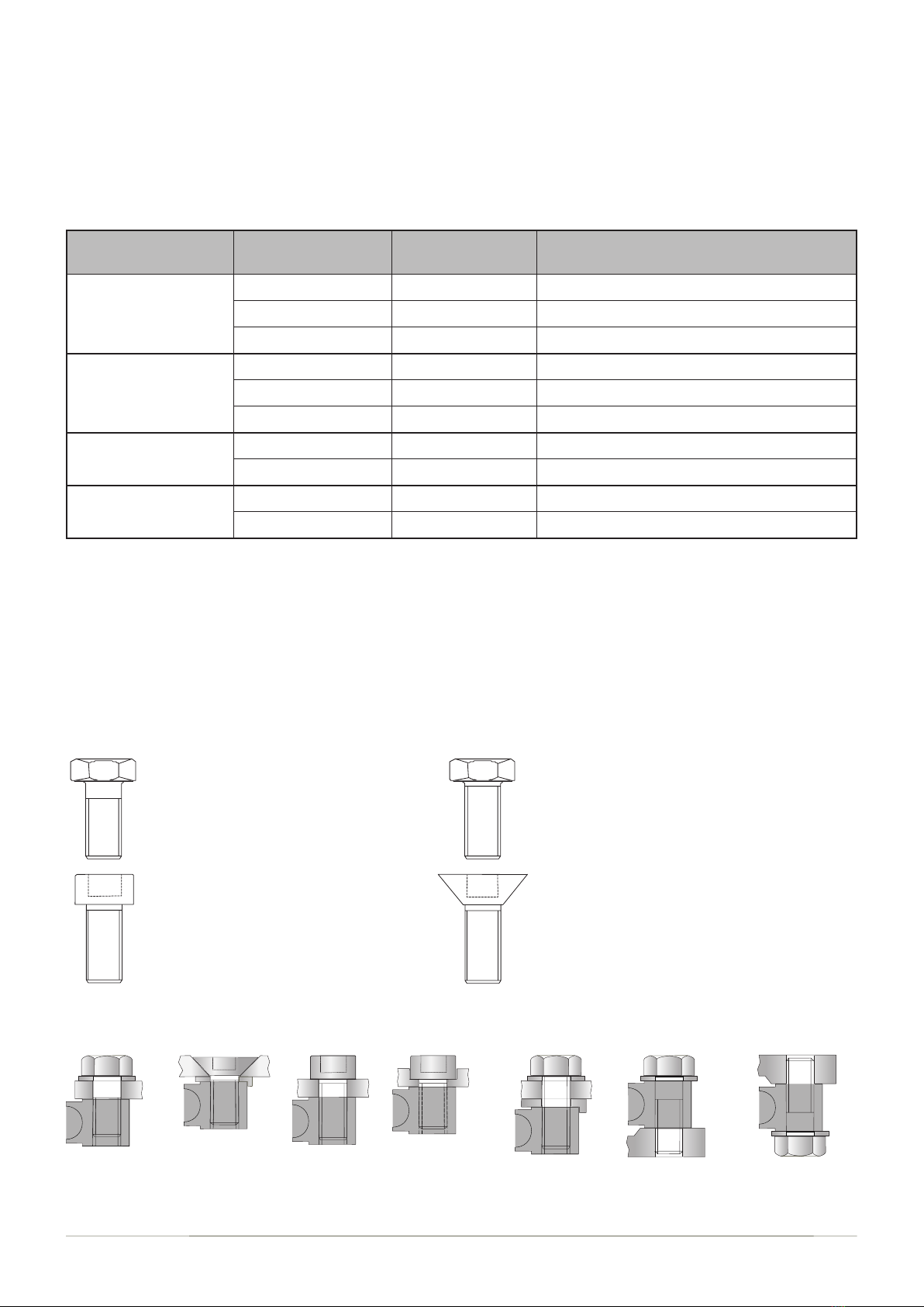
Socket Head Cap Screw
Fullthreadfromendtobolthead.
Suitablefortheendandtopxings.
Washersnotnormallyneeded.
Allowstheheadtoberecessedintothebracketry.
Hexagon Head Screw
Fullthreadfromendtobolthead.
Usewasehers.
Suitablefortheendandtopxings.
Suitableforframemountxings.
Hexagon Head Bolt
Straightshank-partthreadfromendtobolthead.
Usewasehers.
Strongestxing.
Suitablefortheendandtopxings.
Suitableforframemountxings.
Flat Countersunk Socket Cap Screw
Fullthreadfromendtobolthead.
Suitablefortheendandtopxingswhereloadsarelowto
moderatesuchasaweighplatform.
Washersnotnormallyneeded.
Suitableforframemountxingswherecosmeticsandavailable
spaceistight.
Idealwhereatopplateneedtobeushtting
ThexingsintotheDSB7loadcellaremetriconly:M16-1.5(ne)andM24-2(ne)metricxingstoISO/DIN961are
widelyavailableinvariouslengths,checkwiththeFlintecsalesteamsforavailabilityofstockedxings.
Fixings - TherearemanyapplicationsfortheDSB7onawidevarietyoftrucksandmachines.Mountingstyles,bracket
designandchoiceofxingsaretoonumeroustocovereverypossibilityinthisdocument.Thefollowingxingtypes
givesinstallersachoiceoftechniquesandchoiceofxingsforagivenapplication.Factorssuchasappliedforces,
availablespace,xingavailabilityandcosmeticsallcontributetothechoiceofxing.Threadrolledboltsarethe
preferedchoiceinmostcases.Fixinglengthsdependonthicknessofbracketplatesdeployed.
Example xing styles

MSB Flintec 26 November 2014
Installation mounting techniques - axles and axle beams on agricultural machines
13
l In-line
l Bolted to body
l Top and end spacers
l Welded body stiffeners
BODYRAIL
AXLE
or
BEAM
BODY
l Outboard
l End spacers
l Bolted to body rail
l In-line
l Welded ribs
l Load cell inverted
l In-line
l Top spacer
l Welded ribs
l Outboard
l No spacers
l Bolted to body
l Load cell inverted
l In-line
l No spacers
l Welded to body
l Load cell inverted
l Plug welded upper body brackets
l Outboard
l Welded to body
l Load cell inverted
l Load cell on axle beam
l Plug welded upper body brackets
l Outboard
l Bolted to body
l Load cell inverted
minimumairgap:
7.5t=6mm(1/4")
15t=10mm(3/8")
Don'tallowbolts
toprotrudehere

MSB Flintec 26 November 2014
14
DSB 7 footprint dimensions
DSB7 - 7.5T
(16500 Lbs)
DSB7 - 15T
(33000 Lbs)
mm Inch mm Inch
L1 200 7.87" 310 1.22"
L2 96 3.78" 160 6.30"
L3 29 1.14" 40 1.57"
C1 171.5 6.75" 270 10.63"
C2 67.5 2.65" 110 4.33"
H30 1.18" 40 1.57"
H1 0.5 0.02" 2.5 0.09"
W40 1.57" 54 2.13"
T1 M16X1.5 M16X1.5 M24X2.0 M24X2.0
D17-18 0.67"-0.7" 25-26 1"-1.0.4"
X42 1.67" 56 2.20"
Y20 0.79" 30 1.18"
Y1 36 1.42" 48 1.90"
Y2 42 1.65" 54 2.13"
Z6 0.24" 8 0.32"
Z1 12 0.5" 14 0.55"
Optional spacer-canbeaat
squareifpositionedin-linecarefully.
Y2
X
Y
Y1
ZZ1
D
L3 L3
L2
L1
C1
C2
H
4xT1
Optionalspacer
D
D
Specications DSB7 - 7.5 t DSB7 - 15 t
Rated 0utput (RO) 2.0 mV/V ± 1 % at 7.5t 2.0 mV/V ± 1 % at 15 t
Zero balance ≤ ± 0.2 %*RO (or better)
Combined error ≤ ± 0.15 %
Ultimate overload 300 %
Excitation voltage 5...10 Vdc
Input impedance (RLC) 800 ± 50 Ω
Output impedance (Rout) 700 ± 2 Ω
Insulation resistance (100 V DC) ≥ 5 000 MΩ
Operating temperature range °C–30...+70
Stainless steel 17-4 PH
Fully hermetically sealed IP68 up to 2 m (6-1/2") water depth
Protection according EN 60 529 Cable jacket PVC 4 core unshielded cable (AWG 24)
Cable length 5 m, longer or shorter on request
Connector M12 4-pin
Cable diameter 5.5 mm (0.22")
12-15(0.5-0.6")
10-12(0.4-0.47")
NottoScale
8mm
(0.32")
llet
H1
H1
W
12-15(0.5-0.6")

MSB Flintec 26 November 2014
15
MALEplug
mouldedplugconnector
Moulded 4-pin M12 Connector with 5 meters (16.5 ft) of cable
Pin1 Brown +Excitation 5VoltsDC
Pin2 WHITE +Signal millivoltsfromthejunctionbox&loadcells
Pin3 BLUE -Excitation 0Volts
Pin4 BLACK -Signal millivoltsfromthejunctionbox&loadcells
SIGNAL channel 1 & 2, load cell plug is MALE. Cable plug is MALE
Note,wheretheM12connectorisnotrequired,simplycuttheconnectoroff
anduseanalternativeconnectionmethod.
TheIP65modularM12electricalconnectorsystemisaquickandeasywaytowire-up
onboardweighinginstallations,itsavestimeandcutsdownonmistakes.Together,
witharangeofversatileinputs,combinationsofloadcells,sensorsandtransducers
tosuitthousandsofapplicationsarestraightforward.Powerandsignalconnectors
arekey-wayed,genderedandthumbtightened.
Junction boxes
Junction(splitter)boxesareinternallywiredinparallelforanaloguesystemsand
serialforCANOpensystems.4,6and8wayjunctionboxeshaveFEMALE
signalsockets&MALEindicatorcablesockets.
Extender cables & Junction box to indicator cabeles
Onboardweighingloadcellsandextensometershave5metercable
completewithmoulded4-pinM12MALEcableasstandard.Male-Female
extendercablesforlongerreachapplicationsareavailablein1,2,3,5,7.5
&10metrelengths.A2into1‘Y’cableisavailabewheretwoloadcellare
deployed.
Rewirable 4-pin
M12 Connectors
(alsoknownaseldattachments)
MALE
Wirablewithcablegland
CableInstallation
Flinteccablesarespeciallydesignedtoprovidemaximumsignalstrengthand
highreliability.SubstitutionofcablingotherthanFlintecsuppliedcablingmay
causeinconsistentanderraticreadings.Careshouldbetakenwhenrouting
cabletoprovideprotectionfromsharpedges,drivelinerotation,exhaustpipe,
oranyotherpotentialdamage.Secureinplacewithcabletiestoasnugt.
Assemblyofthecableconnectortothejunctionboxandindicatorshould
notbeforced.Alignthe'keyways'andinsertthecableconnector.Asthe
cableconnectorisbeinginserted,rotatethethreadedsleeveclockwise
untilhandtight.Ensuretheconnectorhasbeenfullyinsertedformaximum
moistureprotectionbywrigglingtheconnectorandretighteningthesleeve.
Cable, connectors and cable installation

MSB Flintec 26 November 2014
Installationchecklist
Mountinganglesorplaceshavebeeninspectedforburrs,inconsistenciesandtrueness
Frameshavebeeninspectedandareingoodcondition
Surfacesforloadcellmountingblocksarerigidandhavebeenreinforced
Checkallbearingbracketwelds(seeweldingprocedurepage10)
Checkallboltsaretorquedtospecications(seepage12)
Checkallconnectorsareproperlyinsertedandtightened
Checkallcablesareroutedandsecuredinprotectedareasoftheframe
Indicatorinstallation:seeIndicatorOperatorsManual
Systemcalibration:seeIndicatorOperatorsManual
RoutineMaintenance
Toensureyouronboardweigheroperatessafelyandaccuratelyfollowthesefourperiodicsteps:-
1. Inspectallweldforsignsofcrackingorcorrosion
2. Retightenallfastenerstospeciedtorquevalues
3. Inspectcableandconnectorsfordamage,tightnessandcleanliness
4. Cleantruck/trailersuziconnectors
16
Flintec Group AB
W4/5 Capital Point, Capital Business Park
Wentloog Avenue, Cardiff, CF3 2PW - UK
Tel +44 (0) 29 2079 7959
Fax +44 (0) 29 2079 7939
www.intec.com
This manual suits for next models
1
Table of contents
Other Flintec Accessories manuals


