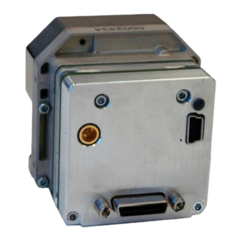
FLIR PTU-D100 E Series User manual

Page1
890CCowanRoad,Burlingame,CA94010●Office(650)692‐3900●Fax(650)692‐3900●[email protected]●www.flir.com/MCS
03/2011
ThisConfigurationGuideliststheconfigurationoptionsandaccessoriesforthePTU‐D100E
Seriespan‐tiltunitswiththeoptionalISMmanufacturedbyFLIRMotionControlSystems,Inc.
AdditionalinformationandinstructionsforPTU‐D100ESerieswithISMareavailableinthe
followingdocuments:
PTU‐D100ESeriesDatasheet
PTU‐D100ESeriesUserManual
Pan‐TiltUnit(ESeries)CommandReferenceManual
ISMUserManual
ModelNumbers
AvailableOptions
ThefollowingconfigurationandoptionsareavailableforthePTU‐D100ESerieswithISM:
BracketMount:Payloadscanbemountedonthetopand/orside.Anumberofbracket
optionsareavailabletosuiteachapplication.Page2.
Wiring:ESeriesPTUswithISMincludePL02wiring.Page3.
RangeofMotion:Ifneeded,youmayrequestspeciallimits.Page4.
Pan‐TiltControls:ThePTU‐D100ESerieswithISMcanbecontrolledusinganASCI
commandset,Ethernet/webconnection,orexternaljoystick.Page5.
Accessories:Availableaccessoriesincludecables,converters,powersupplies,andstarter
kits.Page6.
D100E – S S – G G – 000 – S S
Bracket Mount
S= Dual side hubs
T= Standard
Model
S= Standard
V= D300 EX

PTU‐D100ESeries
Page2
890CCowanRoad,Burlingame,CA94010●Office(650)692‐3900●Fax(650)692‐3900●[email protected]●www.flir.com/MCS
03/2011
BracketMount
ThePTU‐D100acceptspayloadsusingatoporside.Sidemountingofferthehigherpayload
ratingbecauseitreducestiltaxistorque.ThePTU‐D100itselfcanbemountedinany
orientation;however,considerationshouldbegiventogravityandtorqueeffectsdependingon
PTU‐D100orientationandpayloadmountingorientationandbalance.
SideMount
YoumayorderthePTU‐D100withoneortwo
side‐mountbracket(s)withorwithoutatop
bracket.
PartNumber:D100E‐_S‐GG‐000‐__
ToorderaPTU‐D100withoneside‐mount
bracket:
OrderthePTU(D100E‐_S‐GG‐000‐__)
plus
onebracket(D100AC‐BKT‐LSTD).
ToorderaPTU‐D100withtwoside‐mount
brackets:
OrderthePTU(D100E‐_S‐GG‐000‐__)
plustwobrackets
(D100AC‐BKT‐LSTD).
ToorderaPTU‐D100withatopbracketand
oneortwosidebrackets:
OrderthePTU(D100E‐_T‐GG‐000‐__)
plusoneortwobrackets
(D100AC‐BKT‐S)
TopMount
YoumayorderthePTU‐D100withatop‐mount
configurationandincludedtopbracket.
Partnumber:D100E‐_T‐GG‐000‐__

ConfigurationGuide
Page3
890CCowanRoad,Burlingame,CA94010●Office(650)692‐3900●Fax(650)692‐3900●[email protected]●www.flir.com/MCS
03/2011
Base
Receptacle
Payload
Receptacle
PayloadWiring
PTU‐D100unitshaveinternalpass‐throughwiring,
whichprovidesa19‐pinMIL‐C‐26402female
receptacleatthetopofthePTUnearthepayload
locationtoconnectvideo,power,andothersignals.
(Thematingconnectorisprovidedtofacilitatecable
constructionifneeded.)Thesesignalsthenpass
throughthePTU,intotheconnectoratthebaseof
theunit,andthecableharness(ifpurchased).This
optionallowsyoutoreducetheamountofexternal
cablesandeliminatepotentialdamagetoexternal
cables.
ThepayloadreceptaclecontainslinesforVideo
1,Video2,payloadpower,andgeneralpass‐
throughlines.
ThebasereceptaclecontainslinesforVideo1,
Video2,payloadpower,generalpass‐through
lines,PTUcontrol(RS‐232,RS‐485),andPTU
power.
PL02Wiring
PL02allowsyoutoroutesignalstothepayloadas
showninthetablevia13dedicatedconductors.A
matingconnectorforcableconstructionisincluded.
Partnumber:D100E‐__‐GG‐000‐__
PassThrough
Conductors
PL02
Power3
Video4
General6
Total13
SignalsatPayload
TTLOutputs3
PTUHostControl3
CHA/CHBSerial8
BaseConnector
RS‐232HostControl NO
RS‐485HostControlYES
Ethernet/WebYES

PTU‐D100ESeries
Page4
890CCowanRoad,Burlingame,CA94010●Office(650)692‐3900●Fax(650)692‐3900●[email protected]●www.flir.com/MCS
03/2011
RangeofMotion
ThePTU‐D100hasthefollowingstandardfactorypanandtiltaxislimits.Factorylimitsdefine
therangeofmotionallowedforanaxiswhenlimitsareenabled,andthataxiscannottravel
beyondthoselimits.Thebuilt‐inslipringallowscontinuous360°pan‐axismovement(seePage
2).
ISM:ISM‐equippedPTUshaveatiltrangeof+30°/‐85°whenstabilizationisenabled.
Disablingstabilizationprovidesthefullrangeofmotionlistedabove..
Note:YoumayspecialorderaPTU‐D100withcustomhardstopsinstalledand/orwithcustom
bracketpositioning,factoryrangesofmotion,etc.PleasecontactFLIRMotionControl
Systems,Inc.forassistance.
PanRangeOptionsTiltRangeOptions
Partnumber:D100E‐__‐GG‐000‐*_Partnumber:D100E‐__‐GG‐000‐_*
ThepartnumberonyourPTU‐D100withISMmayvaryasshownheretoreflectanyspecial‐
orderedcustomlimits,stops,etc.
ISM

ConfigurationGuide
Page5
890CCowanRoad,Burlingame,CA94010●Office(650)692‐3900●Fax(650)692‐3900●[email protected]●www.flir.com/MCS
03/2011
Pan‐TiltControl
ThePTU‐D300supportsserial,Ethernet/web,binary,andjoystickcontrolinterfacesthat
provideawiderangeofsystemcontrolarchitectures.Thefollowingoptionsareavailable:
ASCIICommandSet
ThePTU‐D300canbecontrolledviathestandard
built‐inserialport(RS‐232orRS‐485)usingsimple
ASCIIcommands.(SeetheESeriesCommand
ReferenceManual.)Thiscanbedoneusinga
terminalprogramoracustomapplication.
Ethernet/WebInterface
ThePTU‐D300canbecontrolledviathestandard
built‐inEthernetportandwebinterface.The
intuitiveinterfacemakesconfigurationanddirect
controleasyusingamouseanddirecttextentry.
GamepadJoystick
AUSBgamepadcontrollerisavailabletocontrola
singlePTUanduptotwoVISCA‐compatible
camerasthatareconnectedtoahostcomputervia
aserialconnection.ThePTUJoystickControlutility
isincludedwithESeriesPTUs.
Partnumbers:PT‐PSC(GamepadController)
Note:CamerasshouldbeconnectedtothehostPCusingadedicatedserialconnectionfor
eachcamera.
RS-232
or
RS-485
Ethernet
USB SERIAL

PTU‐D100ESeries
Page6
890CCowanRoad,Burlingame,CA94010●Office(650)692‐3900●Fax(650)692‐3900●[email protected]●www.flir.com/MCS
03/2011
Accessories
ThefollowingaccessoriesmaybeorderedforthePTU‐D300.Theseaccessoriessimplifysystem
prototypingandfielding.
25’BreakoutCable
Thebreakoutcableconnectstothe32‐pinbaseconnector
(MIL‐C‐26482)onthePTU‐D300andterminatestostandard
connectorsforpower,serialcommunication,Ethernet,and
payloadsignals.Theterminatingconnectorsare:
Power(DIN),2xvideo(composite),RS‐232(DB‐9,female),RS‐
485(RJ11),Ethernet(RJ45),andpayloadpass‐through
conductors.
Partnumber:PTU‐CAB‐E‐25BO
PowerSupply
PTUpowersupplyunit.30VDCoutput,110/220VACinput.
Dimensions:3.44”Wx2.01”Hx7.61”L.
Note:Inputvoltagesunder30Vcanreducethe
maximumspeedoftheunitbyanamountthatis
proportionaltothevoltagedifference.
Partnumber:PTU‐AC‐APS‐30V
StarterKit
ThePTUstarterkitincludesonepowersupply(PTU‐AC‐APS‐30V),one25’breakoutcable(PTU‐
AC‐CAB‐25BO),andoneRS‐485toRS‐232converter(PTU‐CONV‐RS485C).
Note:Inputvoltagesunder30Vcanreducethemaximumspeedoftheunit.
Partnumber:PTU‐KIT‐E‐STR
ExtensionCables
Anextensioncableextendsthelengthofthebreakoutcable.
Thereisamaleconnectorononeendandafemaleconnector
ontheother.Availablein50’and100’lengths.
Partnumbers:PTU‐CAB‐E‐EXT‐50(50’)or
PTU‐CAB‐E‐EXT‐100(100’)

ConfigurationGuide
Page7
890CCowanRoad,Burlingame,CA94010●Office(650)692‐3900●Fax(650)692‐3900●[email protected]●www.flir.com/MCS
03/2011
MatingConnector
Matingconnectorforthe32‐pinbase(MIL‐C‐26482)and19‐
pinpayload(IL‐C‐26402)PTUconnectors.Usethistomake
customPTUand/orpayloadcables.
Partnumbers:PTU‐CABLE01‐19PMILC(19‐pinpayload)or
PTU‐CABLE03‐32PMILC(32‐pinbase)
RS‐485toRS‐232Converter
Bi‐directionalmodulethatconvertssignalsfromRS‐232to
RS‐485.Includespowersupply,coupler,andcable.
Partnumber:PTU‐CONV‐RS485C
RuggedJoystickandCable
ThisruggedjoystickallowsPTUcontrolwithoutahost
computer.Cableorderedseparately.
Partnumbers:PT‐DCJ(joystick)and
PTU‐DCJE‐CABLE(25’DCJconnectioncable)
ESeriesPL01/PL02AdapterCable
ThesecablesallowyoutoconnectanEseriesPTUtoan
existingDseriessetupwithoutrewiring,exceptthatthe
Ethernet/webconnectionwillnotbeavailable.Makesureto
orderthecorrectcableforyourwiringsetup(PL01orPL02).
Partnumbers:PTU‐CAB‐E‐AD‐PL01(PL01)or
PTU‐CAB‐E‐AD‐PL02(PL02)
Other manuals for PTU-D100 E Series
1
Table of contents
Other FLIR Control Unit manuals
Popular Control Unit manuals by other brands

Roger
Roger H70/103AC Installer's instructions

Mottura
Mottura 99.746 Installation & use instructions

Azbil
Azbil ACTIVAL VY51 EJ Series Specifications & instructions

Festo
Festo VMPA2-M1H-...-G1 Series Assembly instructions

Watts
Watts Vision BT-CT02 RF Installation and user guide

Warmworld
Warmworld DATATERM MK2 user guide