Flofab S Series User manual
SINCE 1981
www.flofab.com
001-iom-2017-hesw
Operation, Maintenance
& Installation Manual
Heat
Exchangers
Series S & W

I. Application
II. Operating Principle
III. Construction (Features & Material)
IV. Operating Parameters & Selection of Heat Exchangers
V. Installation
VI. Startup/Shutdown
VII. Operation
VIII. Maintenance
IX. Storage & Transportation
X. Warranty Terms
XI. Warranty Claims Form
XII. Sales & Service
INDEX

SINCE 1981
2
U-tube heat exchangers are designed for a wide range of liquid to liquid and steam to liquid ap-
plications. We offer products of the highest quality and reliability to satisfy your most rigorous
demands.
Typical Applications:
- Domestic Hot Water
- Oil Temperature Cooling
- Liquid & Gas Cooling
A heat exchanger is a device in which heat is transferred from one owing uid to another. Ther-
mal energy is transferred through the tube walls and the total heat load is dependent on the
ow parameters of the uid. Shell and tube heat exchangers are the most common type of heat
exchangers for liquid/liquid service, although many applications also involve steam and certain
gases.
W-line of heat exchangers is designed for liquid to liquid applications, and our S-line of heat
exchangers is designed for steam to liquid applications. Nonnally, the heating medium (e.g. hot
water, steam) ows through the shell side, and the heated medium through the tube side, al-
though this can be reversed depending on the application.
I. APPLICATION
II. OPERATING PRINCIPLE
I.O.M - HEAT EXCHANGERS : SHELL & TUBE, S/W
SINCE 1981
3
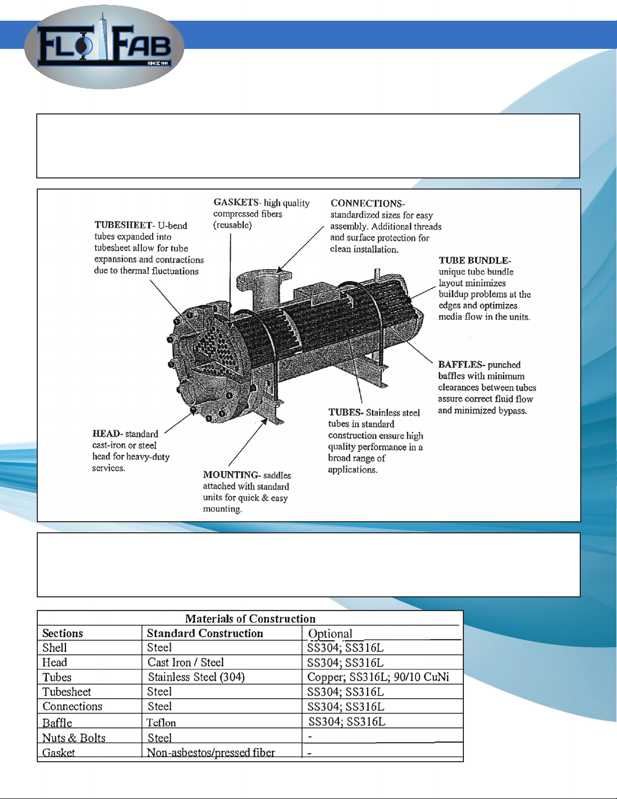
FEATURES
Available in 2 or 4 pass construction, our products are enhanced with stainless steel tubes in
the standard construction, rugged cast iron or steel heads, and unique coil and bafe arrange-
ments to optimize the thermal performance of the heat exchangers.
MATERIAL
S and W-model heat exchangers are manufactured according to the following table, although
optional materials of construction are available to suit specifc customer requirements.
III. CONSTRUCTION
I.O.M - HEAT EXCHANGERS : SHELL & TUBE, S/W

SINCE 1981
4
IV. OPERATING PARAMETERS & SELECTION OF HEAT
Standard maximum working parameters of the heat exchangers are as follows:
Regardless of the application, proper sizing of a heat exchanger is extremely important in ob-
taining the desired thermal performance from the unit. In order to select the most appropriate
product for an application, a customer should specify the following information:
- type of operating medium/uids
- required heat load
- required inlet/outlet temperatures of the heating medium required inlet/outlet temperatures
- of the heated medium
Selection is made through an internally developed software program and distributed to our
customers.
I.O.M - HEAT EXCHANGERS : SHELL & TUBE, S/W
Before installing the heat exchanger into the system, ensure that all the proper piping and
safety gauges are in place:
1. Allow enough space around the heat exchanger to provide sufcient clearance to permit
the removal of the tube bundle from the shell (for maintenance or inspection purposes).
2. Provide valves and bypasses in the piping system so that both the shell side and tube side
may be bypassed to pennit isolation of the heat exchanger for inspection, cleaning, and repairs.
3. Provide thermometer wells and pressure gauge pipe taps in all piping to and from the heat
exchanger, as close as possible to the unit to detect operating performance of the unit.
4. Provide necessary air vent valves for the heat exchanger so that it can be purged to
prevent or relieve vapor or gas binding on both the shell and tube side.
5. Install proper liquid level controls and relieve valves and liquid level and temperature
alanns, etc.
6. Install a surge drum upstream from the heat exchanger to guard against pulsation of
uids caused by pumps, compressors, or other equipment.
V. INSTALLATION
SINCE 1981
5
The S and W-models are designed for horizontal installation. If space is a constraint and vertical
installation is required, please inform the sales ofce.
- Before piping up, inspect all openings in the heat exchanger for foreign material.
Remove all plugs and shipping covers immediately prior to installation.
Do not expose the interior passages of the heat exchanger to. the atmosphere
as moisture and contaminants may enter the unit and cause damage to the system.
- Mounting saddles are attached to the standard unit for quick and easy installation.
- When installing, set heat exchanger level to the ground to ensure no excess
force is required to connect to the system. Install the heat exchanger in a manner where
it will not be exposed to mechanical stresses or moments.
I.O.M - HEAT EXCHANGERS : SHELL & TUBE, S/W
In all startup and shutdown operations, uid ows should be gradual and regulated to avoid
thennal shocking the unit, and every effort should be made to prevent subjecting the heat ex-
changer to overpressure or hydraulic hammers, as these conditions may impose stresses on the
unit that could result in structural damages.
Start-Up:
- Valves should be opened gradually in order to achieve a steady increase in ow and pres
sure into the unit. The pressure increase/decrease should not exceed
72 psi/min (0.5 MPa/min).
- The cold (heated) uid should rst enter into the system.
- The hot (heating) uid, water or steam, should be gradually brought into the system.
- Check all connections for leaks.
Shut-Down:
- Shut down hot uid side rst, then the cold uid side.
Heat exchangers should be used according to the specications given and within pressure and
temperature ranges not exceeding the limits set forth in the section «Operating Parameters &
Selection of Heat Exchangers».
1. Ensure that the system is clean of debris before starting operation to prevent clogging
of tube and shell side passages.
2. Open vent connections before starting up.
3. Follow the instructions in the section «Startup/Shutdown».
4. After the system is completely lled with the operating uid, close all manual vent
connections.
5. Do not operate the heat exchanger under pressure and temperature conditions
exceeding the maximum allowable limit (as specied on the nameplate).
6. Prevent any of the uids form dropping below their freezing point.
7. Drain all uids when shutting down to prevent possible freezing and corrosion.
VI. STARTUP/SHUTDOWN
VII. OPERATION

SINCE 1981
6
I.O.M - HEAT EXCHANGERS : SHELL & TUBE, S/W
Under no circumstances should there be pulsating of uids, as this causes vibrations that could
damage the structural integrity of the heat exchanger. The system should be designed to prevent
the unit from encountering pressure shocks and rapid temperature changes.
CLEANING
Clean heat exchangers subject to fouling (scale buildup, sludge deposits, hard water deposits,
tarnishes, etc.) periodically, depending on operating conditions. Fouling in the unit can result
in increased pressure drops, low temperature differential in the heated medium, or a higher
exit temperature on the heating medium side.
To clean or inspect the tubes, it may be necessary to remove the tube bundle from the shell.
When removing the tube bundle, ensure that there is no damage due to improper handling:
- The weight of the tube bundle should not be supported by
individual tubes, but should be carried by the tubesheet, support or bafe plates.
- Do not handle the tube bundle with hooks or other tools that can damage the tubes.
- To withdraw the tube bundle, pass rods through two or more of the tubes and take the
load on the tubesheet, or alternatively, thread a steel cable through one tube and
return through another tube.
- Lift tube bundles horizontally by means of a cradle formed by bending a light-gauge
plate into a u-shape.
- Do not drag the bundles, as this may cause damage to the tubes and bafes.
Cleansing of the heat exchanger can be done without removing the tube bundles or the unit
from the system, although extra connections and bypasses would be required.
The cleaning solutions are readily assessable at businesses carrying chemical cleaning agents
for heat exchangers or tubing and piping applications. As a guideline to purchasing the cleaning
solutions, check for the following product data:
- compatibility with the material of construction (steel, stainless steel, copper, etc.)
- acceptable for use in food processing industries (if applicable)
- effectively removes scale, slag, tarnishes, and hard water deposits
- easily rinsed out of the system
- no objectionable or corrosive fumes
The following uids are prohibited for use as a ushing agent!!
- Hydrochloric acid up to 0.1 % concentration
- Solutions that contain MCI
- Chlorides (MgCh, NaCl behveen 0.01-1 %, Cu Cl up to 1 %, CaClz from 5% to
saturation)
- Any uid that will deposit alkaline residue or phosphorous
VIII. MAINTENANCE
SINCE 1981
7
LEAKS
To locate ruptured or corroded tubes or leaking joints between tubes and tubesheet, the fol-
lowing procedure is recommended:
- Drain the heat exchanger completely of any uid or moisture.
- Pressurize the shell side of the unit with uid (e.g. water, glycol, etc.)
- Observe the tube joints and tube ends for indication of test uid leakage
During transportation of the heat exchangers, ensure that they are not exposed to mechanical
damages. Upon receipt of the heat exchanger, inspect the unit for shipping damages. Notify the
carrier or the sales ofce immediately in the event that such damages do occur.
Heat exchangers should be stored in a clean, dry, low humidity area away from corrosive envi-
ronments or weather elements (e.g. rain, snow, blowing dust). If the unit is not to be placed in
immediate service, take precautions to prevent rusting or contamination. Heat exchangers that
are out of service for extended periods of time should be protected against corrosion.
IX. STORAGE & TRANSPORTATION
CLEANING:
Shell and tube bundle should be ushed out
periodically. If cleaning is necessary, remove
head and bundle to clean inside of shell and
outside of tubes. Replace gaskets if necessary.
If unit is installed in a hard water area, inside
of tubing can be cleaned as follows:
1. Break water connections and plug bot-
tom opening.
2. Fill the tubes wth a solution of 1 part
muriatic acid to 1 O parts of water
and allow to stand for 2 hours:
CAUTION: A longer period may cause
damage to the copper tubing.
3. Drain off and ush thoroughly wth
clean water.
4. Re-assemble unit.
Note:
Commercially available cleaners may also be
used.
REPLACEMENT PARTS:
When ordering replacement parts specify:
1. Complete Model Number
2. Date of Manufacture
3. Special Materials if Required
Normally, the only replacement parts required
woud be:
1 - Tube Bundle
1 - Set of Gaskets
Replacement heads are also available if re-
quired.
I.O.M - HEAT EXCHANGERS : SHELL & TUBE, S/W

We are proud supplier for the following
completed and on going projects :
Sales and Service :
Quebec, Canada
Tel.: (450) 621-2995
Fax: (450) 621-4995
Lake Worth
Florida, USA
33467-5749
Toronto, Canada
Tel.: +1 (647) 544-2995
www.flofab.com SERVICE 24/7 : parts@ofab.com
Rutgers University
Apartments
604 Bartholomew Road
Piscataway, NJ 08854
Cité du Nouveau Monde
64 rue St-Paul Ouest,
Montreal, QC, H2Y 1Y8
Bella Vista Ltd.,
26 Torbay Road. St.
John’s, NL. A2A 2G4
Le Murray
1169, Rue Ottawa,
Montréal, QC H3C 1S6
This manual suits for next models
1
Table of contents
Other Flofab Industrial Equipment manuals


