Flofab FFWP Series User manual
SINCE 1981
www.flofab.com
001-iom-2017-heffwp
Heat
Exchangers
Series FFWP
& FFWPDW
Operation, Maintenance
& Installation Manual

TABLE OF CONTENTS
1.0 PLATE HEAT EXCHANGERS – WORKING PRINCIPLE
2.0 PARTS & THEIR FUNCTION
2.1 FRAMES
2.2 PLATES
2.3 GASKETS
2.4 FLOW & PLATE ARRANGEMENT
3.0 INSTALLATION
3.1 LIFTING
3.2 INSTALLATION
3.3 PIPING
3.4 STORAGE
4.0 OPERATION
4.1 GENERAL
4.2 STARTING UP
4.3 SHUTTING DOWN
5.0 MAINTENANCE
5.1 OPENING THE HEAT EXCHANGER
5.2 CLOSING THE HEAT EXCHANGER
5.3 GASKETING
6.0 PROBLEM SOLVING
7.0 CLEANING
7.1 FOULING TYPES
7.2 CLEANING PHYSICALLY
7.3 CLEANING IN PLACE
8.0 REPLACEMENT PARTS
Flo Fab was established in 1981 by Denis Gauvreau who created and developed the products line and constantly being perfected by
Marc Gauvreau, as well as by a team of professional engineers and designers. It’s a combination of existing designs from several
renowned products and the innovative ideas of a new generation professionals.
Through the years, Flo Fab has acquired several companies and service entities including : AQUA-PROFAB (ASME Tanks manufac-
turer), MÉNARD, LÉONARD ÉLECTRIQUE, PMA. , Furthermore Flo Fab purchased equipment, fabrication designs and patterns from
IDEALCO, a manufacturer of shell and tube type heat exchangers.
The after sales services, sales, engineering, R&D, production, quality control, accounting and administration departments of all the
above companies share the same location.
In December 2014, Marc Gauvreau, son of the founder, acquired all shares of The company. Flo Fab and is constantly investing in
new state of the art innovations new product like the XRI series and Prefab Skid for Hydronic Hearing 8 cooling system, pumping
systems. This has allowed Flo Fab to retain competent and experienced staff of professionals with varied and specialized abilities
that constantly work on improving our existing products and add new engineered solutions that exceeding customer’s expectations .
Flo Fab has grown quite rapidly and now proudly offers of a wide range of products available directly from one manufacturer. This
includes pumps & pump packages, tanks, heat exchangers & hydronic accessories. This allows each project stakeholders to enjoy
economical savings, peace of mind, best value for their investment and optimized total cost of ownership.
HISTORY
2
2
3
4
5-6
7
7-8
8-9
10
11
11-12
13-14
15-16
17-18
19-20
22-23
23-24
24-25
26

SINCE 1981
2
The Flo Fab FFWP gasketed plate heat exchanger consists of formed chevron plates of corrosion
resistant metals. Every other plate is reversed so the ridges of the herringbone pattern intersect
one another on adjacent plates forming a lattice of contact points. The plates have an elastomer
gasket that is contained in a formed groove to seal the uid between the plates. The plates with
gaskets are then installed in a pressure retaining frame and compressed to form two separate
systems of channels for two media to ow in a countercurrent direction.
The lattice structure causes vigorous turbulence, thus, ensuring maximum heat transfer.
1.0 Plate Heat Exchangers – Working Principle
PLATE AND FRAME - HEAT EXCHANGERS
2.0 Parts & Their Function
2.1 Frames
The frame is made up of thick steel pressure retaining parts, the xed cover and the movable
cover, that when pulled together with the tightening bolts form the pressure retaining structure
for the plates / plate pack.
The carrying bar and guide bar act as a carrier and guide to both the plates and the movable
cover.
SINCE 1981
PLATE AND FRAME - HEAT EXCHANGERS
3
The heat exchanger plates, which make up the heat transfer surface, are clamped between two
plates of steel with the use of the tightening bolts. The heat exchanger construction allows
a plate heat exchanger to be easily opened for inspection and cleaning.
The plate pattern is corrugated and varies depending on the application and the uids being put
through the heat exchanger. As the plate’s corrugation depth gets smaller the thickness of the
plate can be less.
Each heat exchanger plate is formed by pressing in one piece (no seams or welds).
Most plates have four holes punched, one in each corner. The last plate in a single pass
unit has no holes so the uid ow is reversed or turned. Multiple pass heat exchangers have
turning plates with only two holes for redirecting the uid ow.
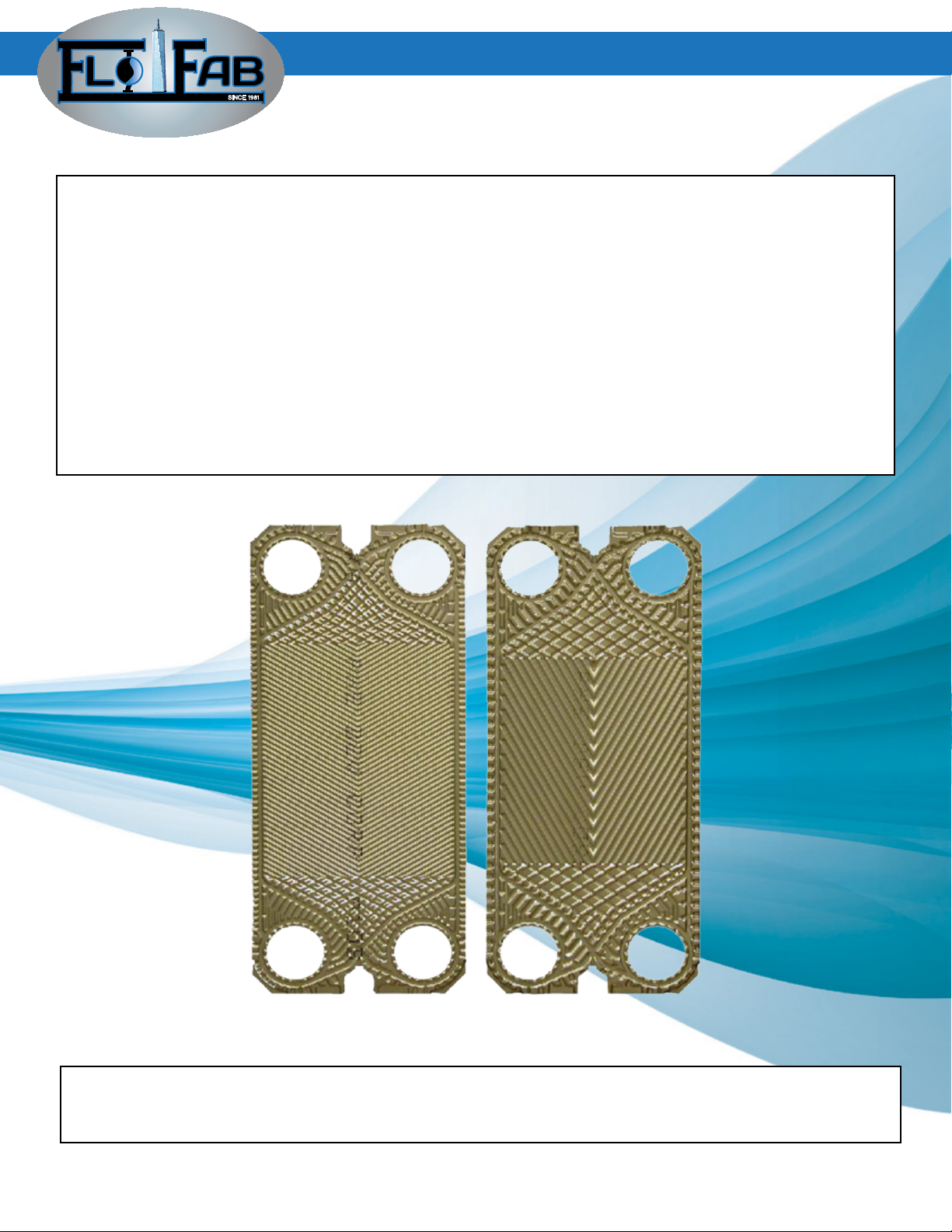
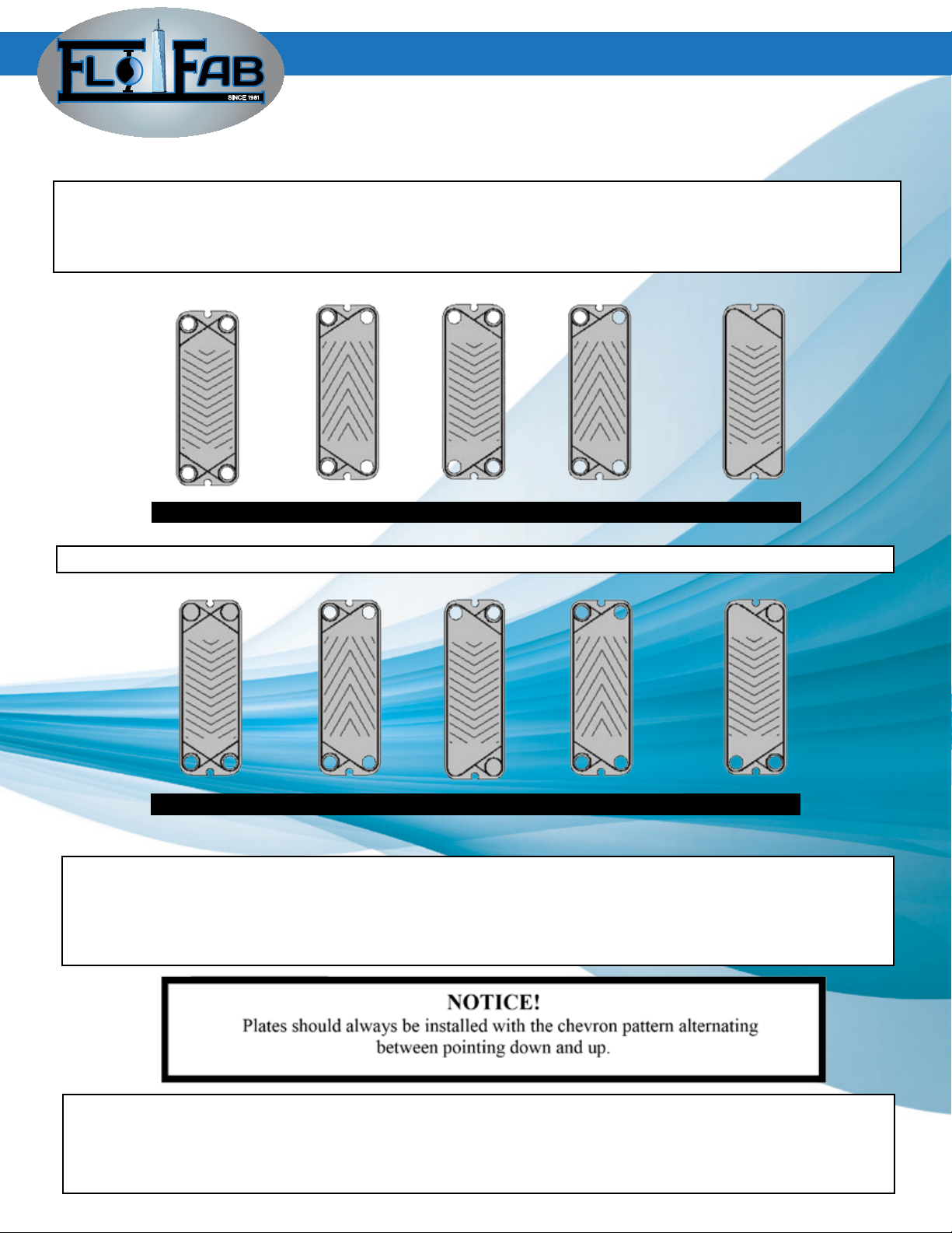
Flo Fab heat exchanger plates are made with two different pressing patterns – one is charac-
terized by an obtuse angle giving a high theta plate, the other with an acute angle giving a
low-theta plate.
2.2 Plates
HIGH-THETA PLATE LOW-THETA PLATE
Between two adjacent plates a ow channel is formed with the aid of the gasket. The liquid ows
straight up or down or in parallel ow. No liquid ows between the plates adjacent to the xed
cover and the moveable cover plate.
SINCE 1981
4
PLATE AND FRAME - HEAT EXCHANGERS
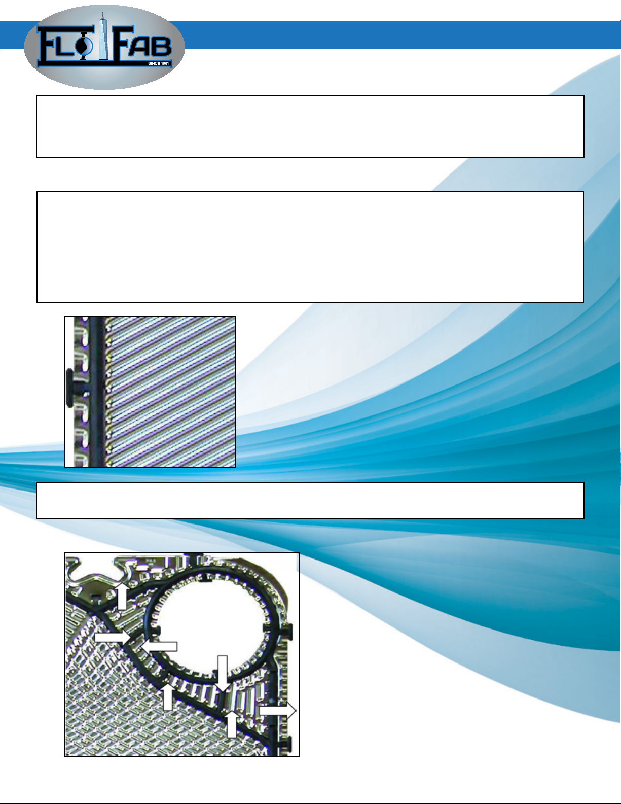
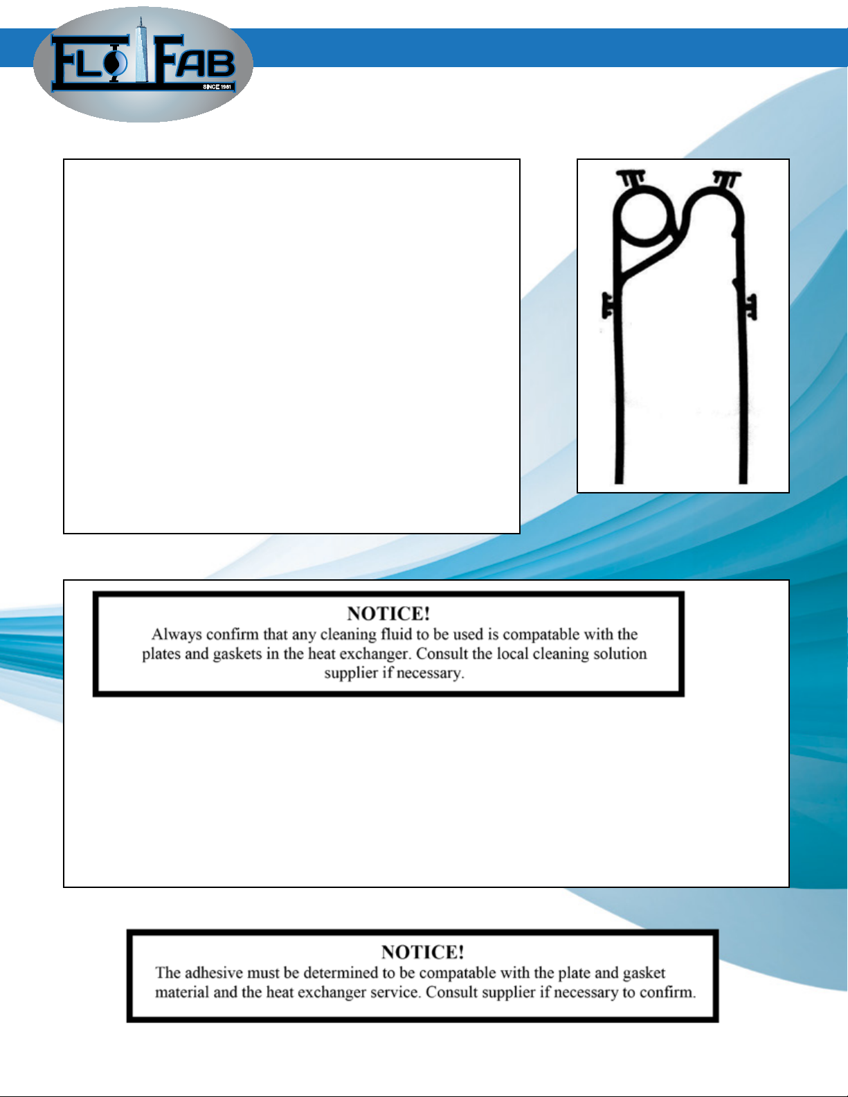
Each plate has a gasket that produces a sealing and channel system through the entire plate
pack in which the two heat exchanging media ow in a counter-current direction.
The circular portion of the gasket stops the uid from going across the heat transfer plate and
sends it to the next open channel. The remaining portion or eld gasket, directs the opposing
uid across the heat transfer surface.
The gasket can be mechanically clipped to the plate with the glue free “U” shaped clip or glued
in place.
2.3 Gaskets
The corrugated chevron pattern is alternated from plate to plate. This gives the plates contact
points for pressure resistance and also forms a liquid stream that is subject to extensive tur-
bulence resulting in a high heat transfer coefcient, as well as reducing the risk of deposits on
the heat transfer surface.
The gasket is double around the ports to prevent intermixing of the two uids. In the event of
gasket failure, any leakage is vented external to the equipment.
Exit to
atmosphere
Each plate has a gasket that produces a sealing and channel system through the entire plate
pack in which the two heat exchanging media ow in a counter-current direction.
The circular portion of the gasket stops the uid from going across the heat transfer plate and
sends it to the next open channel. The remaining portion or eld gasket, directs the opposing
uid across the heat transfer surface.
The gasket can be mechanically clipped to the plate with the glue free “U” shaped clip or glued
in place.
SINCE 1981
5
PLATE AND FRAME - HEAT EXCHANGERS
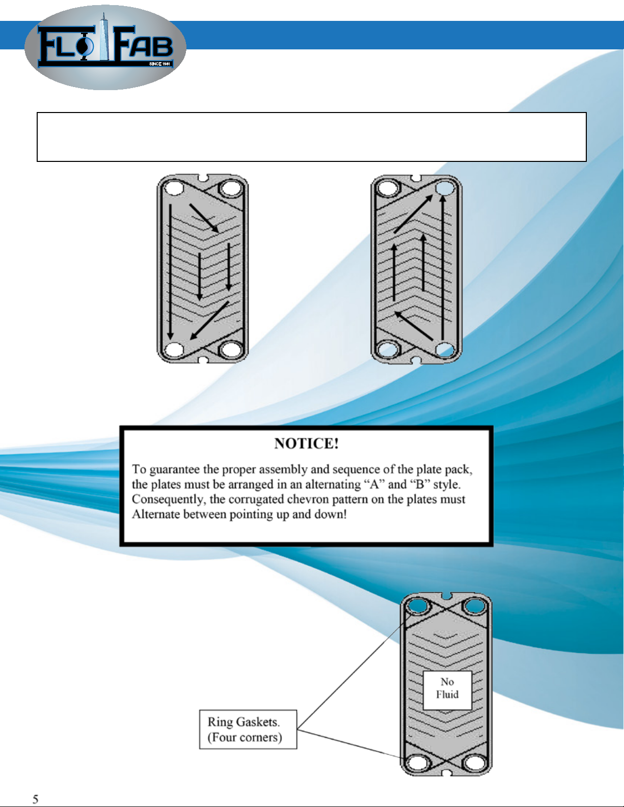
The heat transfer plates with gaskets are arranged in an alternating pattern of left hand ow and
right hand ow to direct the uids in an opposing direction within the in the heat exchanger. The
completed assembly of all the plates and gaskets is called the “plate pack”.
2.4 Flow and Plate Arrangement
“A”
Left Hand Flow
“B”
Right Hand Flow
SINCE 1981
6
PLATE AND FRAME - HEAT EXCHANGERS
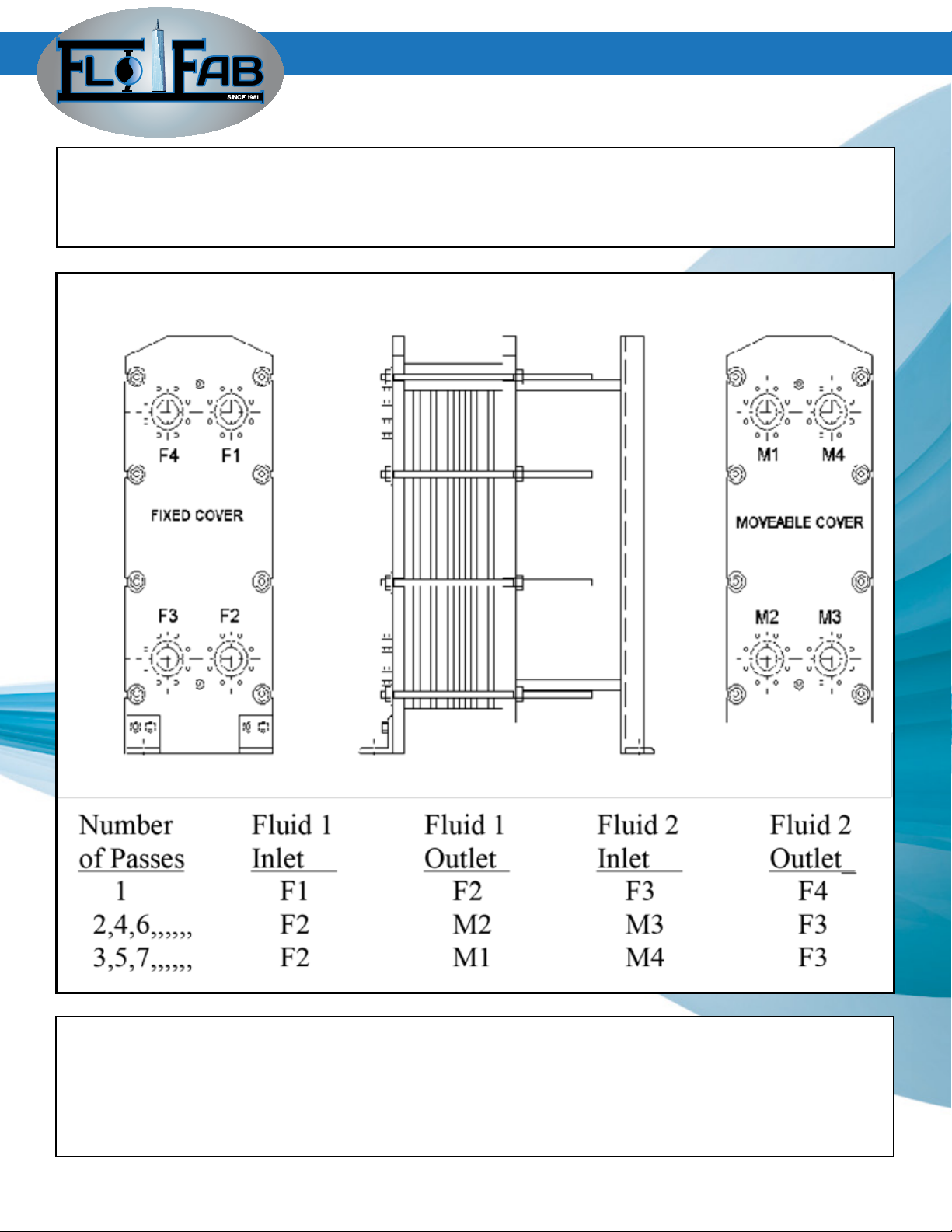
Depending on the number of passes a plate heat exchanger may have, the connection location
may vary. Since all of the heat exchangers are parallel or same side ow, all connections for one
uid will be on the right side and the opposing uid on the left side.
The connection location and typical arrangement are as follows;
Each plate has a gasket that produces a sealing and channel system through the entire plate
pack in which the two heat exchanging media ow in a counter-current direction.
The circular portion of the gasket stops the uid from going across the heat transfer plate and
sends it to the next open channel. The remaining portion or eld gasket, directs the opposing
uid across the heat transfer surface.
An assembled unit must always have the plate chevron pattern rotated 180 degrees from plate
to plate.
The rst plate shall be double gasketed as shown on page 5.
Units with more than one pass will require special circular ring gaskets to seal the Back side of
the last thermal transfer plate to the inside of the moveable cover connections.

SINCE 1981
7
3.0 Installation
3.1 Lifting
The plate heat exchanger shall be lifted by the four lifting holes that are provided
( two in the xed cover and two in the moveable ).
3.2 Installation
The plate heat exchanger is to be mounted vertically on the oor with a level foundation and be
strong enough so no settling occurs that can cause a loading strain on the connections.
The heat exchanger must be Installed with clea-
rance on both sides for maintenance. Under spe-
cial circumstances these dimensions may be re-
duced but the servicing of the heat exchanger
may be compromised.
The foundation for the heat exchanger must be
level and rm enough that no settling occurs
which could put forces and strain on the piping
connected to it.
PLATE AND FRAME - HEAT EXCHANGERS
SINCE 1981
8
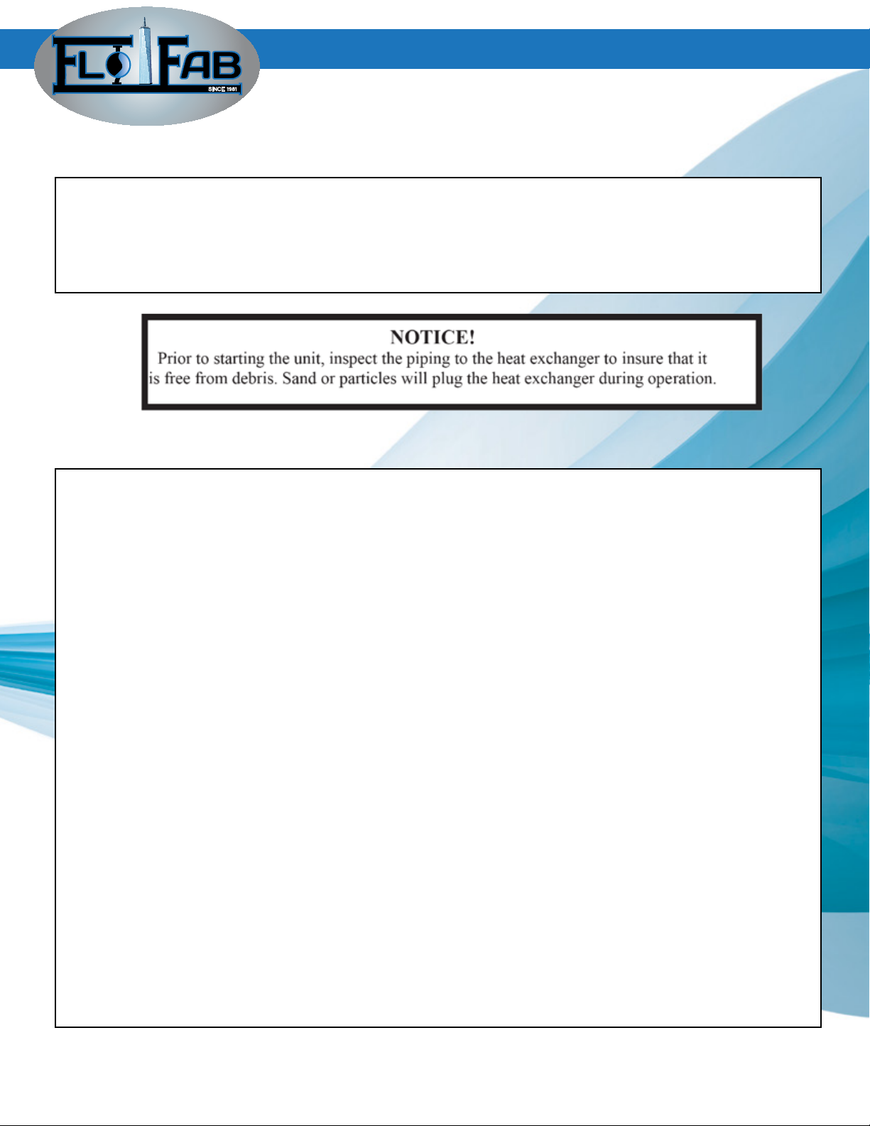
Before installing the piping to the heat exchanger, inspect all the ports for foreign debris that
could become lodged during operation.
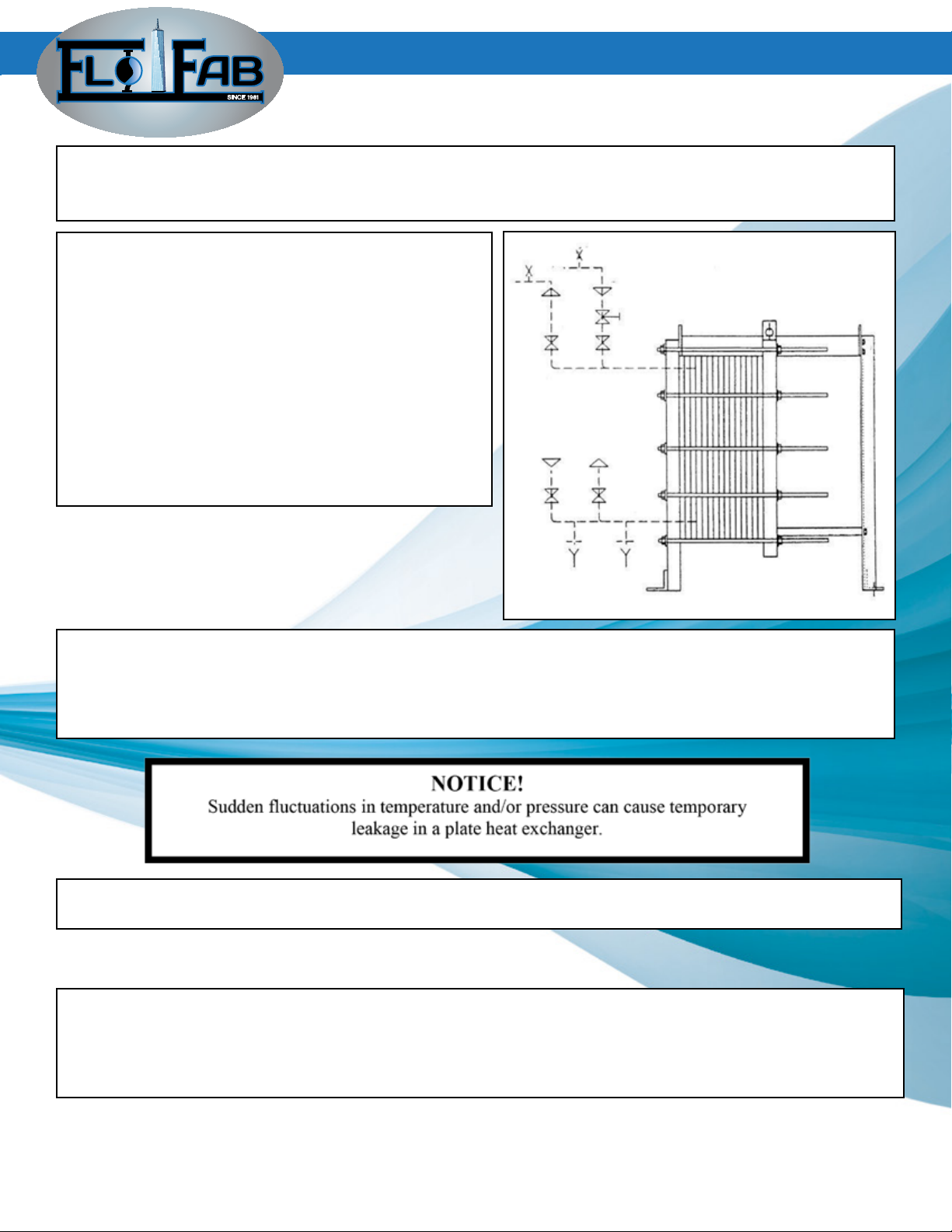
All connections to the heat exchanger must be
provided with shut-off valves (F2,F3,M2,M3). The
upper connections must be provided with venting
devices at their highest points. The hot side re-
gulating valve must be installed in the feed pipe
between the pump and the shut off valve.
To prevent water hammer in the heat exchanger,
quick action valves should not be used.
Provide safety relief valves where the maximum
discharge pressure of the pump can exceed the
design pressure of the heat exchanger.
When the plate heat exchanger is installed in a situation having zero tolerance for process uids
being on the oor, a liquid retaining drip pan with a volume capacity equal to the heat exchanger
shall be mounted under the plate pack to catch and control any leaking uids.
Pumps should have throttling valves and vibration dampers shall be used on positive displace-
ment pumps and especially reviprocating pumps.
For care free and dependable operation of the heat exchanger, avoid sudden pressure and/or
temperature surges.
3.2 Piping
The piping connected to the heat exchanger shall be designed and built so that it’s thermal expan-
sion and weight do not apply any force to the heat exchanger’s nozzle causing premature failure.
Any forces or moments applied to the connections of the heat exchanger must be approved by
Flo Fab
PLATE AND FRAME - HEAT EXCHANGERS
SINCE 1981
9
PLATE AND FRAME - HEAT EXCHANGERS
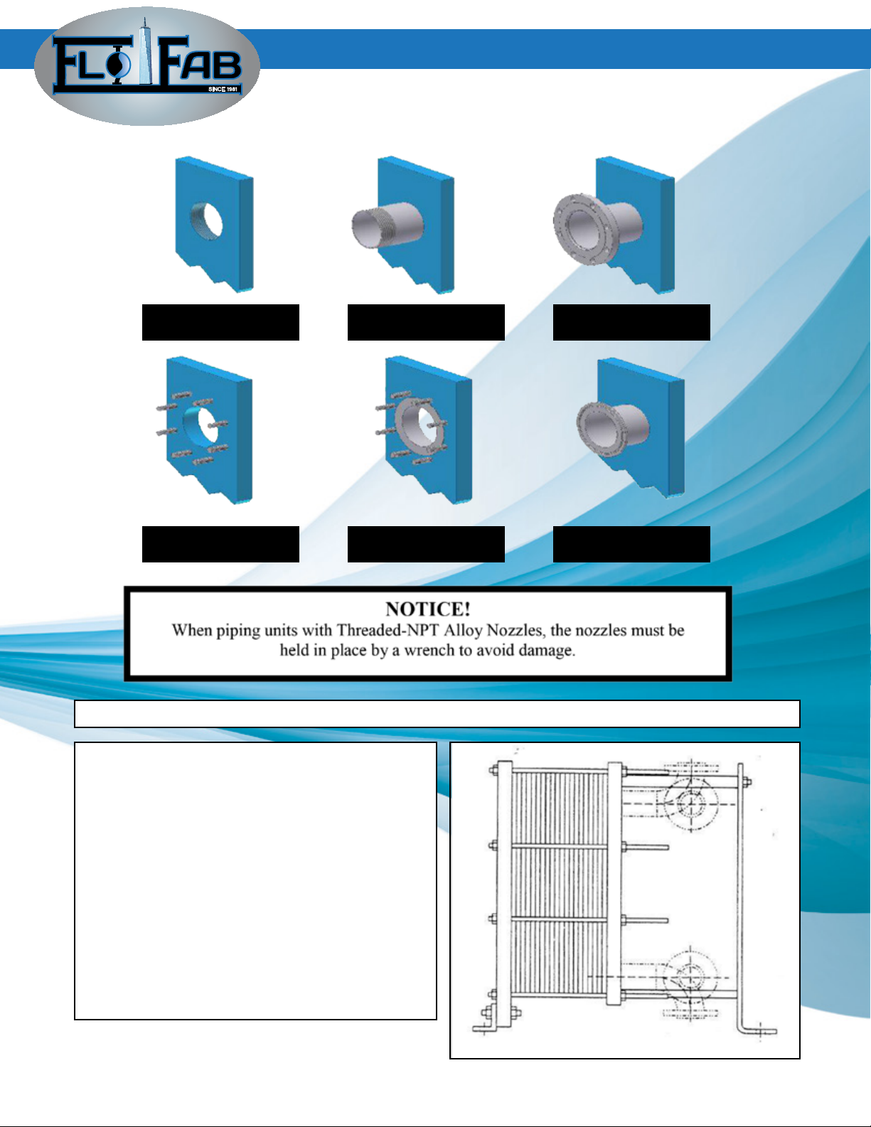
The following shows typical connections available on the heat exchangers;
Threaded - NPT
Carbon Steel
Studded - ANSI
Carbon Steel
Threaded - NPT
Alloy Nozzle
Studded - ANSI
Alloy Lining
Flanged-
ANSI
Ferrule-
Quick Disconnect
When the heat exchanger has connections on the moveable cover there are special piping
• The moveable cover is not xed so it’s
nozzles can withstand less loading than the
nozzles on the xed cover.
• The unit may be subject to re-tightening
during service, therefore when attaching
piping to the moveable cover you must
allow for this difference
(approximately plus or minus 1% of nal
tightening dimension).
• The moveable cover goes backward for
servicing. Use elbowed spool pieces for
easy removal.

SINCE 1981
10
PLATE AND FRAME - HEAT EXCHANGERS
3.4 Storage
If the heat exchanger is to be placed in long term storage, the following steps should be taken;
• Store heat exchanger in a closed room at 60 to 70 degrees F
• The heat exchanger tightening bolts and plate pack shall be completely un-tightened and
stress free.
• The heat exchanger should be totally covered in black plastic to prevent light and dirt from
adversely affecting the gaskets.
• Avoid heat, ultraviolet and welding light.
• Apply a rust preventative to all machined carbon steel parts including bolts and anged faces.
SINCE 1981
11
PLATE AND FRAME - HEAT EXCHANGERS
Check that the operating pressures and temperatures do not exceed those stated on
the heat exchanger nameplate.
Check that all tightening bolts are properly tightened.
Be certain the plate pack tightening dimension ( “T” ) matches the nameplate or
assembly drawing before pressurizing the heat exchanger.
4.0 Operation
4.1 General
The lower pressure and temperature operating uid side should always be introduced
rst to the heat exchanger during start up;
1) Totally shut off the valve located between the pump and the heat exchanger inlet.
2) Open fully the valve located at the outlet connection.
3) Open the vent valve.
4) Start the pump.
5) Open the valve between the pump and the inlet to the heat exchanger very slowly!
6) When all the air is bled from the system close the vent valve
7) Repeat steps 1 through 6 for the other uid side.
When using steam in the heat exchanger there are special considerations to follow;
• Never have the steam side on with the liquid / cold side turned off.
• Steam inlet shall always be a top connection with an outlet condensate drain at the bottom.
• Steam must always be turned on second and shut off rst
• The steam valves must open gradually to avoid damaging the plates.
• Bring steam side up to design conditions slowly by controlled throttling of the
cold side uid to prevent shocking the heat exchanger.
4.2 Starting Up

SINCE 1981
12
PLATE AND FRAME - HEAT EXCHANGERS
Shutting down should take place slowly;
1) Slowly close the valve between the pump and the inlet connection of the heat heat exchanger
for the uid at the higher pressure and temperature.
2) Turn pump off.
3) Close the valve on the outlet side of the heat exchanger.
4) Repeat this procedure for the other uid side.
If the heat exchanger is to be out of service for an extended period of time or requires mainte-
nance, vent and drain the heat exchanger. Prior to storage rinse and clean the plates to remove
any foreign substance.
Storage procedures on page 10 are recommended for any heat exchanger that will be out of
service for a month or longer. This is especially recommended when there is a risk of freezing or
if the media in the heat exchanger is corrosive.
4.3 Shutting Down
SINCE 1981
13
PLATE AND FRAME - HEAT EXCHANGERS
5.0 Maintenance
5.1 Opening the Heat Exchanger
The heat exchanger must have been shut down in accordance with the previous section ( 4.3).
Allow the heat exchanger to stand and cool to room temperature, preferably overnight and
drain in accordance with the previous section.
1) If the heat exchanger has connections on the
moveable cover, the piping must be removed to al-
low the cover to move backward for opening.
2) The upper carrying bar should be inspected and
wiped clean.
3) Clean the threads of the tightening bolts with a
wire brush and then apply a thin layer of molybde-
num disulphide or other equivalent grease for lubri-
cation.
3) Remove the safety shield from the unit.
4) To keep the plates in the proper order when re-
moving them, they can either be sequentially mar-
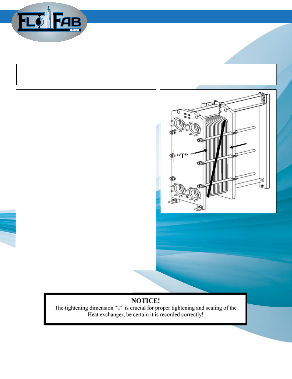
ked as they are removed or a diagonal line can be
drawn across the plate pack to record each plate’s
position.
5) Record the actual plate tightening dimension “T”,
the distance between the inside edges of the xed
and moveable covers.
6) If the tightening bolt assemblies for the heat ex-
changer have a locking washer under the nut at the
moveable cover, all tightening can be done from the
nuts located at the xed cover.
The heat exchanger must have been shut down in accordance with the previous section ( 4.3).
Allow the heat exchanger to stand and cool to room temperature, preferably overnight and
drain in accordance with the previous section.
SINCE 1981
14
PLATE AND FRAME - HEAT EXCHANGERS
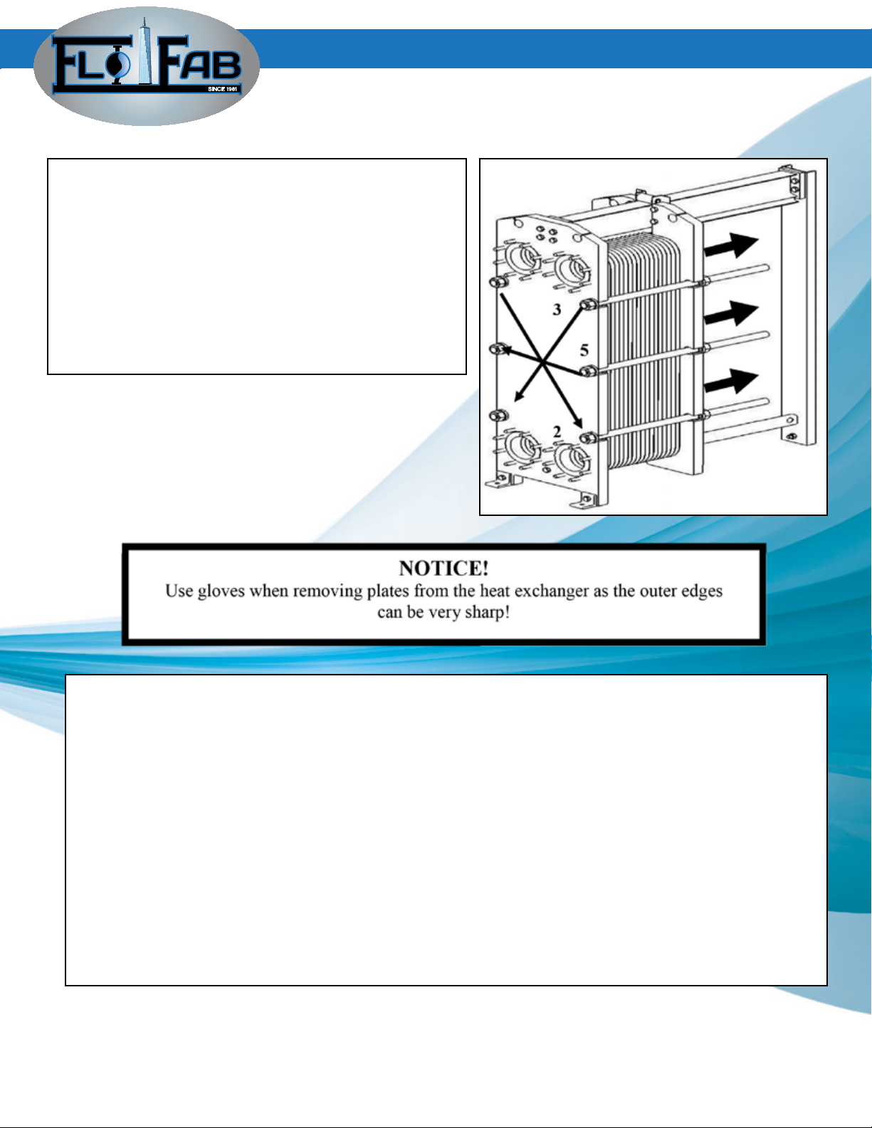
7) Open the heat exchanger by diagonally loosening
tightening bolt pairs. Keep the xed and moveable
cover parallel during opening by loosening each nut
in ¼” to ½” increments. This will avoid damage to
the heat transfer plates.
8) After all the tension is removed from the tighte-
ning bolts and they are loose, they can be taken
out and the moveable cover slid or rolled backward
to allow access to the plates for inspection and/ or
removal.
The heat transfer plates are now removed as follows;
• Move the bottom end of the heat transfer plate diagonally back until it’s lower end is clear of
the lower guide bar.
• Rotate the bottom end of the plate outward until it’s side is clear of the lower guide bar and
now the plate is removed by moving it slightly downward to free it from the upper carrying bar
• Either remove or add plates with this method.
If two or more plates are stuck together, they must be seperated carefully, so that the gaskets
are kept with the correct plate.
The heat transfer plates support each other in pairs. If a plate has been so damaged that it must
Be taken out and cannot be repaired or replaced with an identical one, it’s adjacent plate must
also be removed.
SINCE 1981
15
PLATE AND FRAME - HEAT EXCHANGERS
5.2 Closing the Heat Exchanger
Starter Plate Low Plate High Plate Low Plate End Plate
Starter Plate Low Plate Turning Plate Low Plate End Plate
Prior to installing the heat transfer plates consult the plate arrangement drawing to insure the
proper sequencing of the plates.
Typical single pass plate arrangement;
Typical multi pass plate arrangement;
1) Check that all sealing surfaces are clean.
2) Check that the sealing surface at the connections are smooth and free from burrs or debris.
3) Install the plates one at a time with the gasket facing the xed cover and push them forward
until they stop.
4) Prior to pushing the plates forward examine them to make certain the gasket is in it’s correct
position and that it is clean. Wipe the gasket surface with a clean cloth if necessary to remove
any foreign material.
5) The upper carrying bar and lower guide bar should be cleaned and lubricated.
SINCE 1981
16
PLATE AND FRAME - HEAT EXCHANGERS
6) If the plates were diagonally marked prior to their removal, verify the plates are in the proper
order before tightening.
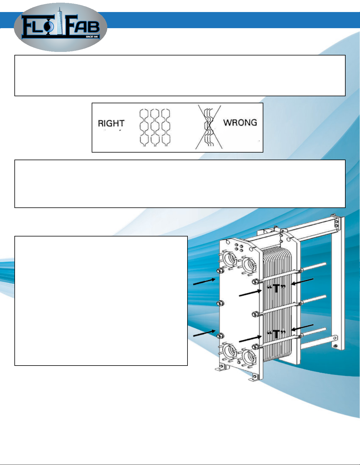
6) If the plates are assembled correctly the plate edges will form a honeycomb pattern and If glue-
less gaskets are used the external tabs will be alligned.
8) Set the tightening bolts into position on the frame and wire brush them and apply a thin layer of
grease.
7) Begin tightening the heat exchanger by alternating between diagonally opposite bolt pairs contra-
ry to the opening procedure. During the tightening process, the distance between the xed and mo-
veable cover measured at all points shall differ more than ¼” to ½”.
8) During tightening check the “T” dimension at four
points nearest the bolts being used to close heat
exchanger.
9) Tighten the heat exchanger until the “T” dimen-
sion is equal +/- 1% of the dimension specied on
the drawing or nameplate or a new dimension based
on the addition or removal of plates.
10) All tightening bolts must be under tension.
11) After fully tightening the heat exchanger,
the difference between the “T” dimension at any
adjacent bolt shall not exceed 1/16”. The “T” di-
mension must not differ by more than 1% for all
tightening bolts.
SINCE 1981
17
PLATE AND FRAME - HEAT EXCHANGERS
5.3.1 Glueless or glue free gaskets are provided for most
models. These gaskets are replaced as follows;
1) Peel the old gasket off of the plate and make certain all
parts of it are totally removed.
2) Wipe the gasket groove clean making sure no foreign
materials remain that could cause the gasket to seat im-
properly.
3) Secure the new gasket to the plate by sliping the gas-
ket tabs under the edge of the plate. Note that there are
two tabs at each attachment location at regular intervals
around the circumference of the plate.
4) Prior to closing the heat exchanger make sure all the
gasket tabs are in the proper position.
5) The plate heat exchanger is then closed and tightened
with the gaskets providing a tight seal.
5.3 Gasketing

SINCE 1981
18
PLATE AND FRAME - HEAT EXCHANGERS
4) The amount of adhesive required can be estimate as follows;
Models: WP10 – WP41 WP45 – WP61 WP80 – WP140
Plate Size: up to 3 sq. ft. up to 7 sq.ft up to 20 sq.ft.
Ounces/plate: 0.50 1.00 1.50
5) Visually inspect the gasket groove before applying the adhesive to make certain it is clean
and dry.
6) Rough the at side of the gasket that will be bonded to the plate using sand paper or an
emery cloth.
7) Use a short hard brush to apply a thin layer of adhesive in the gasket groove.
8) After the glue becomes tacky, which could take 5 to 10 minutes, carefully line the gasket
up with the groove and press it in.
9) A gasket’s dimensions may change slightly after forming. If gaskets are too short they
must be stretched by pulling prior to installation and gaskets that are long should have the
short ends installed rst and then press the gaskets in moving toward the middle of the plate.
10) Carefully stack the plates and put weight on top and alow the adhesive to dry per the
manufacturer’s guideline.
5.3.3 Endplate gaskets that seal the rst heat transfer plate against the xed cover and in
units being multipass or having connections on the moveable cover sealing to the last heat
exchager plates require special consideration.
The gasketing on the rst or starter heat transfer plate is made by cutting two standard gas-
kets and attaching them to the plate as shown;
SINCE 1981
19
6.0 Problem Solving
The following is a guide for trouble shooting a heat exchanger that may not be performing
as expected. If more assistance is required please contact Graham personnel.
SYMPTOM : Fluid is leaking between two heat transfer plates and to the outside.
CAUSE: A gasket is loose or damaged.
SOLUTION: Mark or record which plate is leaking and open the heat exchanger in accordance
With section 5.1. Examine the plate in question to see if the gasket has become dislodged
from it’s groove or damaged. Reposition or replace the gasket as necessary.
CAUSE: The heat exchanger is not fully tightened.
SOLUTION: Count the number of heat transfer plates in the heat exchanger to verify the cor-
rect number. Tighten the heat exchanger in accordance with Section 5.2 until the leak stops.
CAUSE: A heat transfer plate has been damaged due to overightening or physical abuse.
SOLUTION: A damaged plate typically must be removed from the heat exchanger and either
repaired or replaced. Mark the leaking plate, open the heat exchanger in accordance with
Section 5.1, remove the plate and replace it with a new one.
If a replacement plate is not readily available, an option for making the unit operable is as
follows;
1) Remove the damaged plate.
2) If the damaged plate is a standard four hole plate, you should also remove the plate
immediately before or after it.
3) Close the heat exchanger in accordance with Section 5.2.
4) Due to the removal of some plates the heat exchanger must know be tightened to a re-
duced
dimension. Consult Graham engineers for a new appropriate dimension.
CAUSE: A heat transfer plate is misalligned in the heat exchanger.
SOLUTION: Mark and remove the leaking plate. Carefully repair the plate hanging or corner
allignment section of the plate so it alligns properly in the heat exchanger. If the plate still
hangs incorrectly in the heat exchanger it must be replaced with a new one. Close the heat
exchanger in accordance with section 5.2.
PLATE AND FRAME - HEAT EXCHANGERS
This manual suits for next models
13
Table of contents
Other Flofab Industrial Equipment manuals


