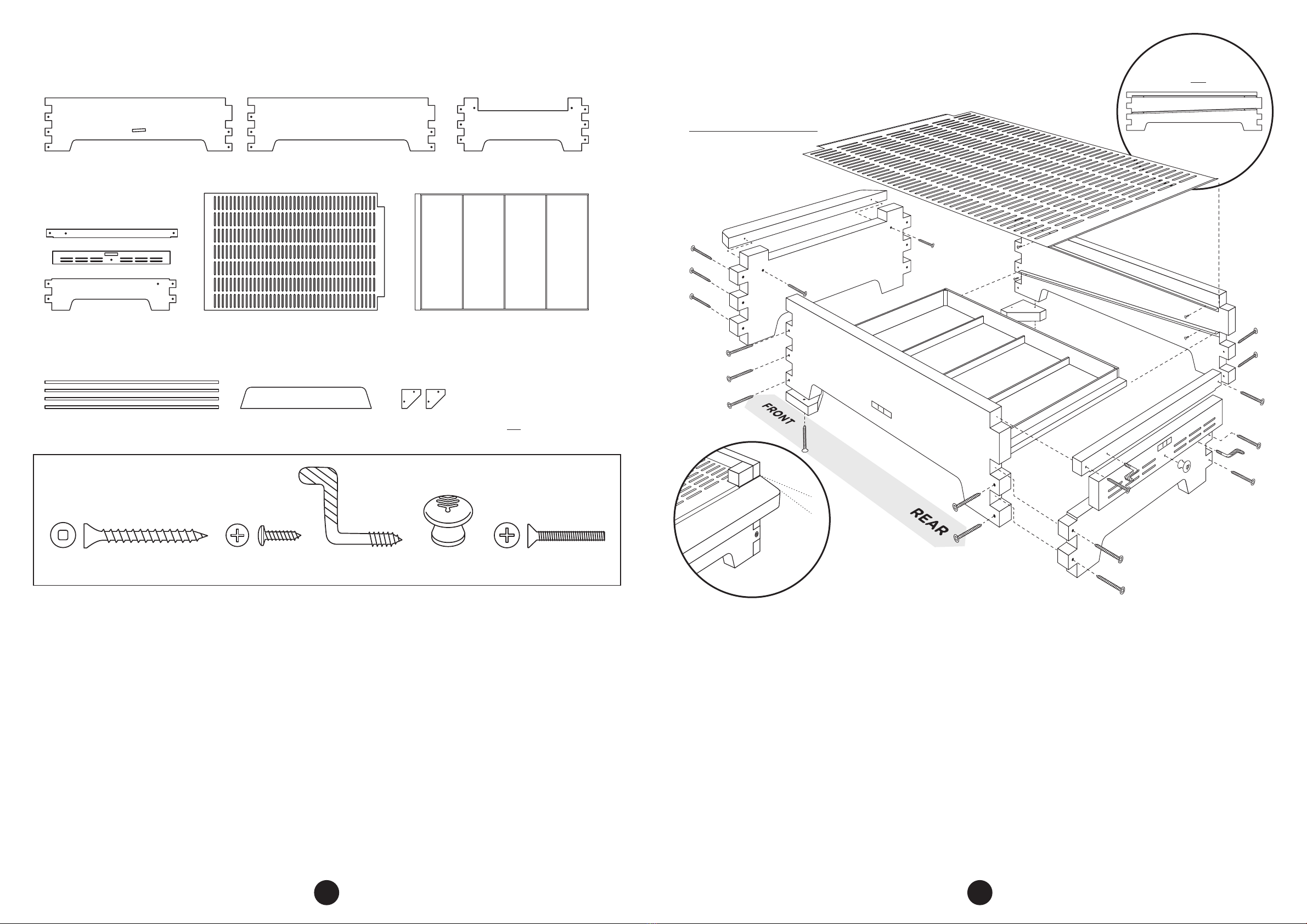
Flow HIVE 2 User manual

FLOW®HIVE 2
ASSEMBLY GUIDE
If we look
after the bees they will look
after us, and the honey really
is an amazing bonus.
AUSTRALIAN
MADE
FLOW HIVE 2: CEDAR 6 & 7 FRAME, PAULOWNIA 6 FRAME, ARAUCARIA 6 & 7 FRAME
FLOW HIVE 2 BROOD BOX

Building a Flow Hive usually takes a
couple of hours, so it’s a good idea to leave time
and space to spread out your components to
ensure that your assembly goes smoothly.
To assist you in identifying the parts for each
of the major components we have included a
pictorial guide at the beginning of each set
of instructions.
PLEASE NOTE: Flow Hive 2 – 6 frame illustrations
shown throughout. Flow Hive 2 – 7 frame model
will vary slightly in appearance .

3
HARVESTING
SHELF
LEG
KIT
(OPTIONAL)
PAGE
17
PAGE
16
HIVE CONFIGURATIONS
TIMBER FINISHES, HOW TO USE THE BASE TRAY,
HOW TO USE THE INBUILT SPIRIT LEVELS
PAGES
18-19
HARVESTING CHECKLIST PAGE
20
BROOD
BOX &
BROOD
FRAMES
PAGES
12-13
NOTE: IDENTIFYING FLOW SUPER AND BROOD BOX PARTS
It’s important to note that your Flow Super and Brood box panels may appear
to be the same, however, these have a few minor dierences which need be
identified, to avoid confusion.
The brood box end panels can be distinguished from the Flow Super front panel, by
the inclusion of an extra set of pilot holes on the finger joints (see images below).
The Flow Super side panels can be easily identified as the panels which contain a
window cutout, stepped box joint and metal bracing strip notch, all of which are
absent from the Brood Box side panels.
BASE PAGES
14-15
FLOW
SUPER
PAGES
10-11
ROOF
CEDAR & PAULOWNIA
6 FRAME - PG 6
ARAUCARIA 6 FRAME - PG 7
ARAUCARIA 7 FRAME - PG 8
CEDAR 7 FRAME - PG 9
PAGES
6-9
FLOW SUPER PARTS
Flow Super side panelFlow Super front panel
BROOD BOX PARTS
Brood box side panelBrood box end panels
Extra pilot holes

4 5
COMPONENTS OF A FLOW HIVE 2
ROOF
INNER
COVER
with plug
FLOW
SUPER
QUEEN
EXCLUDER
BROOD
BOX
with brood
frames
Flow Key
access
cover
Tray
Vented
cover
Latch
Latch
Rear
window
cover
Rear
window
HARVESTING
SHELF
BRACKETS
(optional)
Side observation
window
Side observation
window cover
Your Flow
Frames will
sit in here
BASE
LEG KIT
(optional)
• It is important to read all instructions before assembling, however,
if you’re like most of our Flow team, you may find our assembly videos
extremely helpful. These can be viewed at www.honeyflow.com/assembly
• If you are unfamiliar with constructing beehives, you may like to
ask a friend or someone from your nearest beekeeping club to help.
• If short on time, the Flow Super can be constructed at a later date,
as this will not be added to your hive until your colony is well
established in the brood box.
• Timber is a natural product and will expand and contract in dierent
climate conditions.
• Don’t be alarmed if you have extra screws and hardware as we have
included spares.
• When fastening the square drive screws, stop when the screw head
is still slightly proud of the box to avoid splitting the timber.
TOOLS YOU WILL NEED
(NOT SUPPLIED)
• Hammer (for brood
frames)
• Non-toxic wood glue
• Suitable wood finish
(see page 19). Many
customers find it useful
to apply this finish
before adding windows,
latches and knobs.
• Carpenter’s square
(optional)
• Clamps 41cm and 51cm
(optional)
• Power drill (optional)
use only with low
torque setting. Must
be used with care to
avoid splitting the
timber.
TOOLS INCLUDED FOR ASSEMBLY
*PLEASE NOTE: The assembly tool is located
in the super hardware pack along with drive
bits. Additional drive bits are located with
the brood hardware kit.
Assembly tool
(L - wrench)
Sandpaper
No.2
Phillips
head
drive bit
No.2
square
drive
bit
Roof
alignment
block

6 7
1. Screw the roof rails and gables together (using the
square drive bit and square drive screws) as shown.
• The Flow logos face toward the outside.
• Match the slope of the rails with the slope of the
gable. The angle should align at both ends.
• The roof rail end that aligns with the rear gable
(shorter gable) has a second cut out to allow space
for the key access cover once assembled.
2. Check the roof is square prior to axing the shingle
panels.
• Hint: You can use the inner cover and some packing
material to hold it square while you ax the
shingles.
3. To ax the roof shingles, place them so that
the underside of the panels match with the roof
alignments on the gables.
4. Line up the holes in the shingle panels with the roof
gables. The roof overhangs the front and rear gables
by 27mm (1.06 inches). Use the roof alignment block
to measure this overhang
5. Check once again that the roof assembly is square
and that the holes in the shingles are correctly aligned
with the gable ends. Screw the shingles into position
(square drive bit and square drive screws).
• Take care with this stage to make sure the screws
are positioned square to the shingle and run into the
gable (so they don’t break through).
6. Line up the ridge cap with the roof shingles. Screw the
ridge cap down as shown.
7. To secure the roof, locate the two brass wing screws.
Screw into the pilot holes in the side rails. These can
be used to secure your roof in high wind areas.
PARTS
ASSEMBLY
ROOF ASSEMBLY - CEDAR & PAULOWNIA 6 FRAME
1 x front gable – tall
1 x rear gable – short
1 x ridge cap
1 x left side & 1 x right side rail
ROOF SCREW PACK – ACTUAL SIZE
17 x square drive screws
2 x brass wing screws
2 x shingle panels
roof
alignment
block
drive
shingle
screws on
slight
angle
1. Screw the roof rails and gables together (using the
square drive bit and square drive screws) as shown.
• The Flow logos face toward the outside.
• Match the slope of the rails with the slope of the
gable. The angle should align at both ends.
• The roof rail end that aligns with the rear gable
(shorter gable) has a second cut out to allow space
for the key access cover once assembled.
2. Check the roof is square prior to axing the shingle
panels.
• Hint: You can use the inner cover and some packing
material to hold it square while you ax the
shingles.
3. To ax the roof shingles, place them so that
the underside of the panels match with the roof
alignments on the gables.
4. Line up the holes in the shingle panels with the roof
gables. The roof overhangs the front and rear gables
by 27mm (1.06 inches). Use the roof alignment block
to measure this overhang
5. Check once again that the roof assembly is square and
that the holes in the shingles are correctly aligned with
the gable ends. Screw the bottom shingle into position
first (square drive bit and square drive screws), then
apply some wood glue to the join between the two
roof shingles to create a good weather barrier, before
axing the top shingle.
• Take care with this stage to make sure the screws
are positioned square to the shingle and run into the
gable (so they don’t break through).
6. Line up the ridge cap with the roof shingles. Screw the
ridge cap down as shown.
7. To secure the roof, locate the two brass wing screws.
Screw into the pilot holes in the side rails. These can
be used to secure your roof in high wind areas.
PARTS
ASSEMBLY
ROOF ASSEMBLY - ARAUCARIA 6 FRAME
1 x front gable – tall
1 x rear gable – short
1 x ridge cap
1 x left side & 1 x right side rail
ROOF SCREW PACK – ACTUAL SIZE
17 x square drive screws
2 x brass wing screws
4 x shingle panels
drive
shingle
screws on
slight
angle
roof
alignment
block

8 9
1. Screw the roof rails and gables together (using the
square drive bit and square drive screws) as shown.
• The Flow logos face toward the outside.
• Match the slope of the rails with the slope of the
gable. The angle should align at both ends.
• The roof rail end that aligns with the rear gable
(shorter gable) has a second cut out to allow space
for the key access cover once assembled.
2. Check the roof is square prior to axing the shingle
panels.
• Hint: You can use the inner cover and some packing
material to hold it square while you ax the
shingles.
3. To ax the roof shingles, place them so that
the underside of the panels match with the roof
alignments on the gables.
4. Line up the holes in the shingle panels with the roof
gables. The roof overhangs the front and rear gables
by 27mm (1.06 inches). Use the roof alignment block
to measure this overhang
5. Check once again that the roof assembly is square and
that the holes in the shingles are correctly aligned with
the gable ends. Screw the bottom shingle into position
first (square drive bit and square drive screws), then
apply some wood glue to the join between the two
roof shingles to create a good weather barrier, before
axing the top shingle.
• Take care with this stage to make sure the screws
are positioned square to the shingle and run into the
gable (so they don’t break through).
6. Line up the ridge cap with the roof shingles. Screw the
ridge cap down as shown.
7. To secure the roof, locate the two brass wing screws.
Screw into the pilot holes in the side rails. These can
be used to secure your roof in high wind areas.
1. Screw the roof rails and gables together (using the
square drive bit and square drive screws) as shown.
• The Flow logos face toward the outside.
• Match the slope of the rails with the slope of the
gable. The angle should align at both ends.
• The roof rail end that aligns with the rear gable
(shorter gable) has a second cut out to allow space
for the key access cover once assembled.
2. Check the roof is square prior to axing the shingle
panels.
• Hint: You can use the inner cover and some packing
material to hold it square while you ax the
shingles.
3. To ax the roof shingles, place them so that
the underside of the panels match with the roof
alignments on the gables.
4. Line up the holes in the shingle panels with the roof
gables. The roof overhangs the front and rear gables
by 27mm (1.06 inches). Use the roof alignment block
to measure this overhang
5. Check once again that the roof assembly is square
and that the holes in the shingles are correctly aligned
with the gable ends. Screw the shingles into position
(square drive bit and square drive screws).
• Take care with this stage to make sure the screws
are positioned square to the shingle and run into the
gable (so they don’t break through).
6. Line up the ridge cap with the roof shingles. Screw the
ridge cap down as shown.
7. To secure the roof, locate the two brass wing screws.
Screw into the pilot holes in the side rails. These can
be used to secure your roof in high wind areas.
PARTS
ASSEMBLY
ROOF ASSEMBLY - ARAUCARIA 7 FRAME ROOF ASSEMBLY - CEDAR 7 FRAME
1 x front gable – tall 1 x front gable – tall
1 x rear gable – short 1 x rear gable – short
1 x ridge cap
1 x left side & 1 x right side rail
ROOF SCREW PACK – ACTUAL SIZE
17 x square drive screws
2 x brass wing screws
4 x shingle panels
drive
shingle
screws on
slight
angle
roof
alignment
block
PARTS
ASSEMBLY
1 x ridge cap
1 x left side & 1 x right side rail
ROOF SCREW PACK – ACTUAL SIZE
17 x square drive screws
2 x brass wing screws
2 x shingle panels
roof
alignment
block
drive
shingle
screws on
slight
angle

10 11
ASSEMBLY
FLOW SUPER ASSEMBLY
SUPER HARDWARE PACK – ACTUAL SIZE
2 x Flow Super side panels
with observation windows
1 x Flow Super front panel
1 x metal bracing strip
1 x Flow Key access cover
1 x rear fixed panel
1 x rear window cover
1 x rear window latch 4 x acrylic frame spacers
PARTS
1. To attach the acrylic frame spacers to the left and
right side panels, remove the plastic film and line up
with the pilot holes on the inside ends of the super
side panels.
2. Ax spacers (Phillips head driver bit and the frame
spacer screws).
• Face countersink bevel outwards to house screw
shape.
3. Dry fit the 2 super side panels, super front panel and
rear fixed panel together as shown.
• If finger joints are tight due to expansion or
contraction, use the sandpaper (supplied) to adjust.
• Make sure the 6 pilot holes surrounding the window
face the inside of the box.
• Do not screw the rear window cover in place as
this piece will be used to gain access to the Flow
Frames.
4. Hold the finger joints tightly together (clamp optional)
and use the assembly tool (square drive bit and square
drive screws) to secure through the pilot holes. Take
care to stop when the head is flush with the wood
surface. If using a drill, be careful not to overtighten
or the wood may split.
5. To ax the metal bracing strip, turn the super upside
down. Align the metal strip with the notch on the
bottom of the side panels. Screw in to place using the
assembly tool (Phillips head driver bit and two metal
bracing strip screws) Optional: Pre-drilling may avoid
splitting the wood.
Note: You may wish to apply a suitable timber finish before
installing windows and latches
6. Remove protective plastic film from both sides of
the observation windows and line up with the 6 pilot
holes. Attach the acrylic windows (using the Phillips
head driver bit and window screws) to the inside of
the box. Do not use a drill for this step as it is easy to
overtighten and crack the acrylic window).
7. Ax the 2 brass L screws into the pilot holes (by
hand) on either side of the observation window on the
outside of the box. Wind in until they almost scrape on
the external box side.
8. Locate the 2 observation window covers and 2 brass
knobs. Ax the knob using the brass knob screw and
tighten by hand until the head of screw is flush with
the wood. You can now put the window covers in
place using the brass L screws to secure them.
9. Place a spring onto the rear window latch screw and
use the screw to ax (Phillips head drive bit) the rear
window latch onto the rear fixed panel of the super at
the pilot hole. The spring will prevent over-tightening
of the screw and allow this latch to move easily.
10. Place the Flow Key access cover above the rear fixed
panel, and turn the rear window latch to secure it in
to place.
11. When you install your Flow Super make sure to place
the queen excluder between the brood box and super
(see establishing colony configuration pg.16). We have
plenty of resources online to help give guidance on
when to add your Flow Super.
2 x springs 3 x brass knob screws3 x brass knobs
21 x square drive screws
2 x observation windows 2 x window covers
4 x brass L screws
21 x window/
frame spacer screws
1 x rear window latch screw
2 x metal strip screws Do not
screw this
cover in
place
Attaching
acrylic
frame
spacers

12 13
1. Lay out all the pieces for a single frame on a flat
surface.
2. Apply a small amount of glue to the u-shape
slots on the end panels, then fit the top and
bottom bars into the slots. Glue is not completely
necessary but will make the frame more robust.
3. Check that the frame is square, then nail all
pieces together.
4. Glue comb guides in only when using natural
foundation in your brood box. If you plan to use
a plastic or wax foundation (not supplied) do
not use the comb guide strips. Turn frame upside
down, add a few drops of glue to the slot on the
underside of top bar and insert the comb guide.
5. Repeat for remaining frames.
IMPORTANT: When installing your
bees, make sure the brood frames
are pressed together in the centre of
the box with any extra space spread
evenly across both outside edges.
1. Dry fit the 2 brood box side panels and 2 brood
box end panels together as shown.
• If finger joints are tight due to natural timber
expansion or contraction use the sandpaper
(supplied) to adjust.
2. Hold the finger joints tightly together (clamp
optional) and use the assembly tool (square
drive bit and square drive screws) to secure
through the pilot holes. Take care to stop when
the head is flush with the wood surface. If using
a drill, be careful not to overtighten or the
wood may split.
2 x brood box end panels2 x brood box side panels
PARTS ASSEMBLY
ASSEMBLY
BROOD BOX ASSEMBLY
2 x end
panels
PARTS (SHOWN FOR SINGLE FRAME ONLY)
1 x top bar
1 x comb guide
1 x bottom bar
BROOD FRAME ASSEMBLY
glue
glue
glue
glue
BROOD FRAME HARDWARE – ACTUAL SIZE
65 x nails
BROOD BOX SCREW KIT – ACTUAL SIZE
29 x square drive screws

14 15
BASE ASSEMBLY
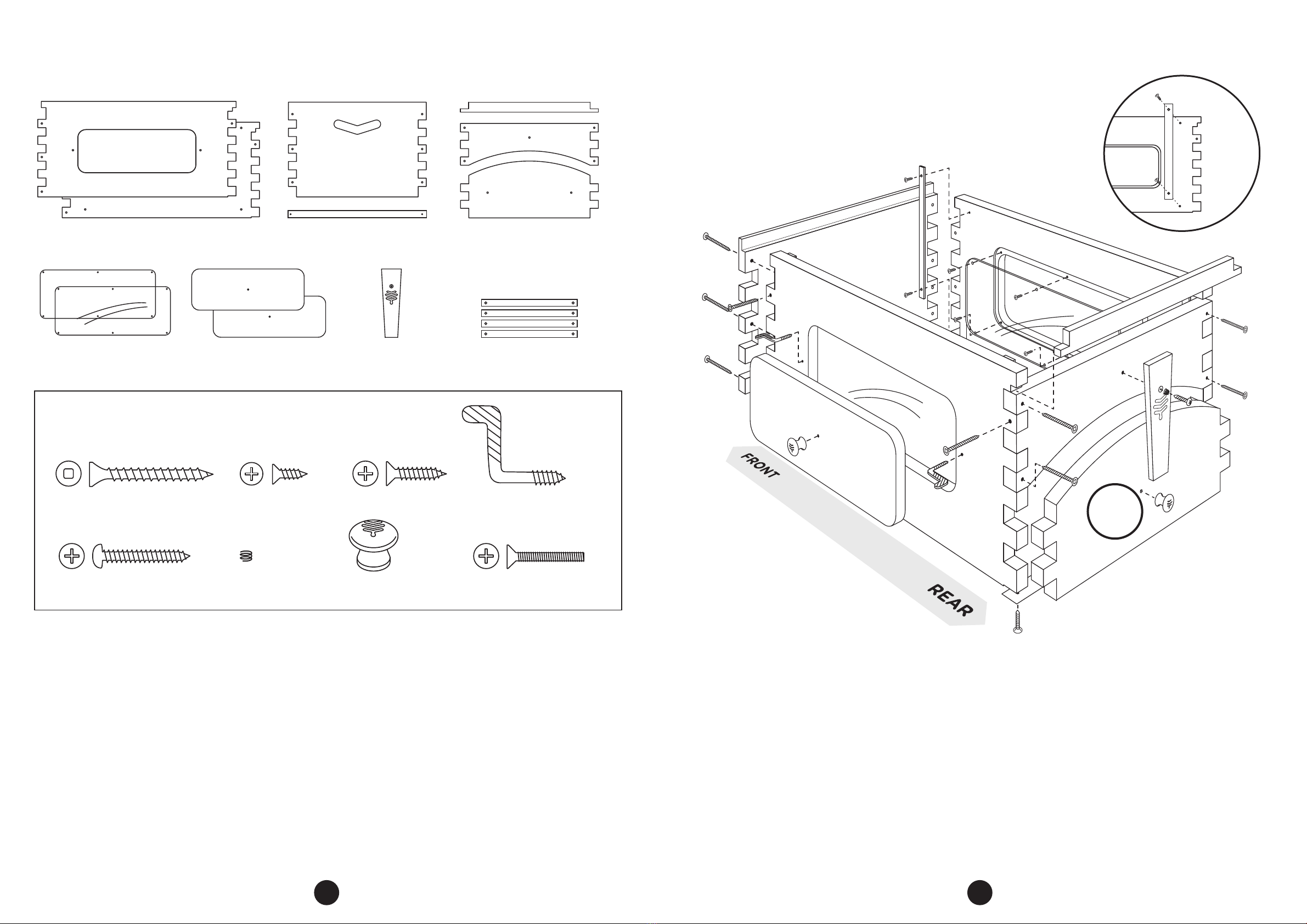
• These L screws sit asymmetrically (see diagram).
Screw in until they almost scrape on the external
box side.
8. To attach the brass knob onto the rear vented cover
(with spirit level), insert the knob screw through the
pilot hole and tighten by hand until the head of the
screw is flush with the wood. You can now put the
base rear vented cover in place using the brass L
screws to secure it.
• The base rear vented cover can be used in two
positions. Place vents on the top side to assist with
ventilation, or turn upside down with vents at the
bottom to block ventilation.
• The vented cover should touch the acrylic tray to
create a sealed surface on the inner edge.
9. Remove plastic protective layer from the metal screen
and place onto the top side of metal rails so that the
entrance lip slopes down to touch the landing board.
10. To create an optimal harvesting slope on the base for
customers who do not have the optional leg kit, you
will need to attach the 2 footblocks to the front of
the base (the front is the side with the landing board
attached). Line up each footblock so that the corners
match and using the square drive bit, screw 2 square
drive screws into the pilot holes.
• Your base includes a side panel spirit level, which
indicates when the base is sloped to the optimal
harvesting angle (3°). Once you have attached your
2 footblocks, check the spirit level to ensure that
your base is sloped for optimal harvesting.
• Please also note; there are 6 pilot holes in the
bottom corners of the base for the optional leg
kit. Disregard these pilot holes if you have not
purchased this.
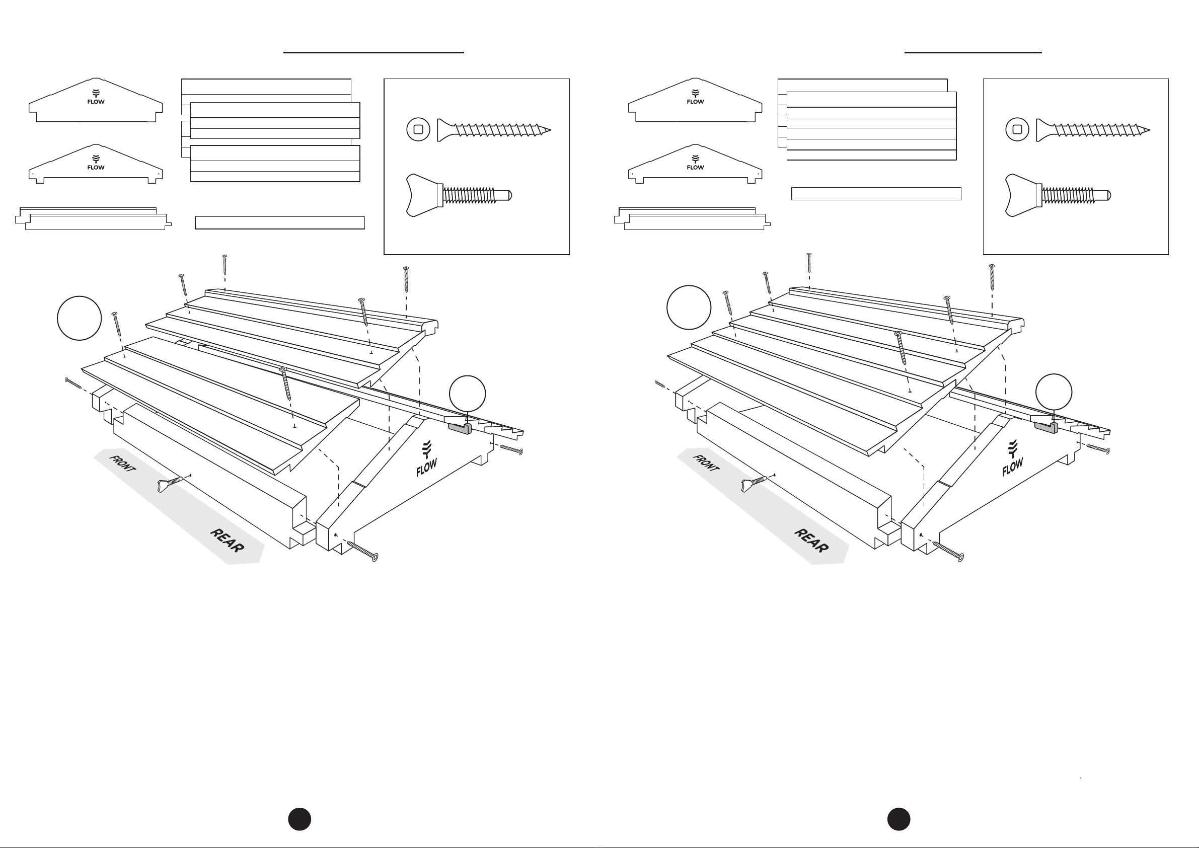
1. Dry fit the base sides, rear and front panels together.
• The 4 small pilot holes on each side panel (for
supporting the metal rails, acrylic tray and metal
base screen) face the inside.
2. Hold the finger joints tightly together (clamp optional)
and use the assembly tool and square drive bit to
secure your base (square drive screws). Take care to
stop when the head is almost flush with the wood
surface. If using a drill, be careful not to overtighten
or the wood may split.
3. Attach the rear support beam (square drive screws) to
the top rear of the side panels with a gap between the
support beam and the base rear panel (this is where
the rear vented cover will sit, but do not attach this).
4. Centre the landing board at the front of the base and
attach to the front panel using the pilot hole locators
(square drive screws), as shown, with a downward
angle to deter rain from entering the hive.
5. Now ax the 4 metal rails to the inside face of the
side panels (Phillips head driver bit). These rails will
house the acrylic tray and metal screen. Line up the
screw holes in each metal rail with the internal side
panel pilot holes.
• The right angle rails mount with the holes on the
underside (and forms a shelf on the top edge).
• Repeat on each side panel to create two small
horizontal bracket shelves on each side as shown.
• The rails are not parallel. The bottom rail slopes
toward the front.
6. Slide the acrylic tray into place through the gap
between the rear panel and the rear support beam.
• When the tray is in place, a gap remains for
ventilation.
7. Locate the 2 brass L screws and screw them into the
pilot holes by hand on the rear panel and the rear
support beam.
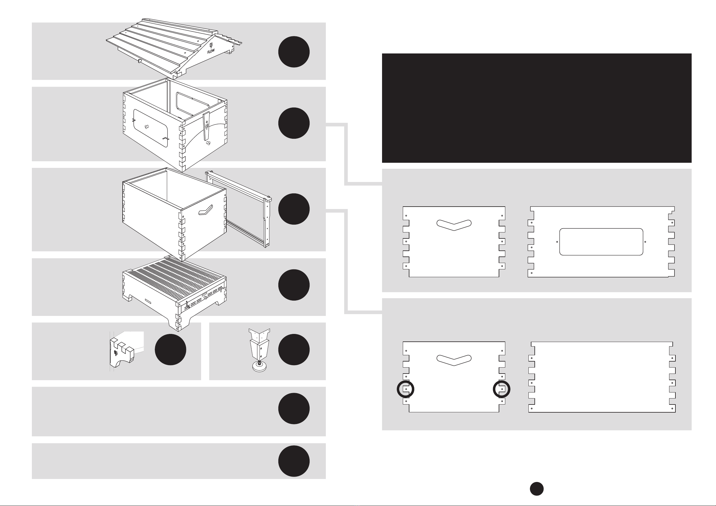
1 x side panel left (with spirit level) 1 x side panel right 1 x front panel
1 x metal screen
1 x landing
board
2 x footblocks –for use if not
installing the optional leg kit
PARTS ASSEMBLY
1 x rear support beam
1 x rear vented cover
(with spirit level)
1 x rear panel
4 x metal rails
1 x tray
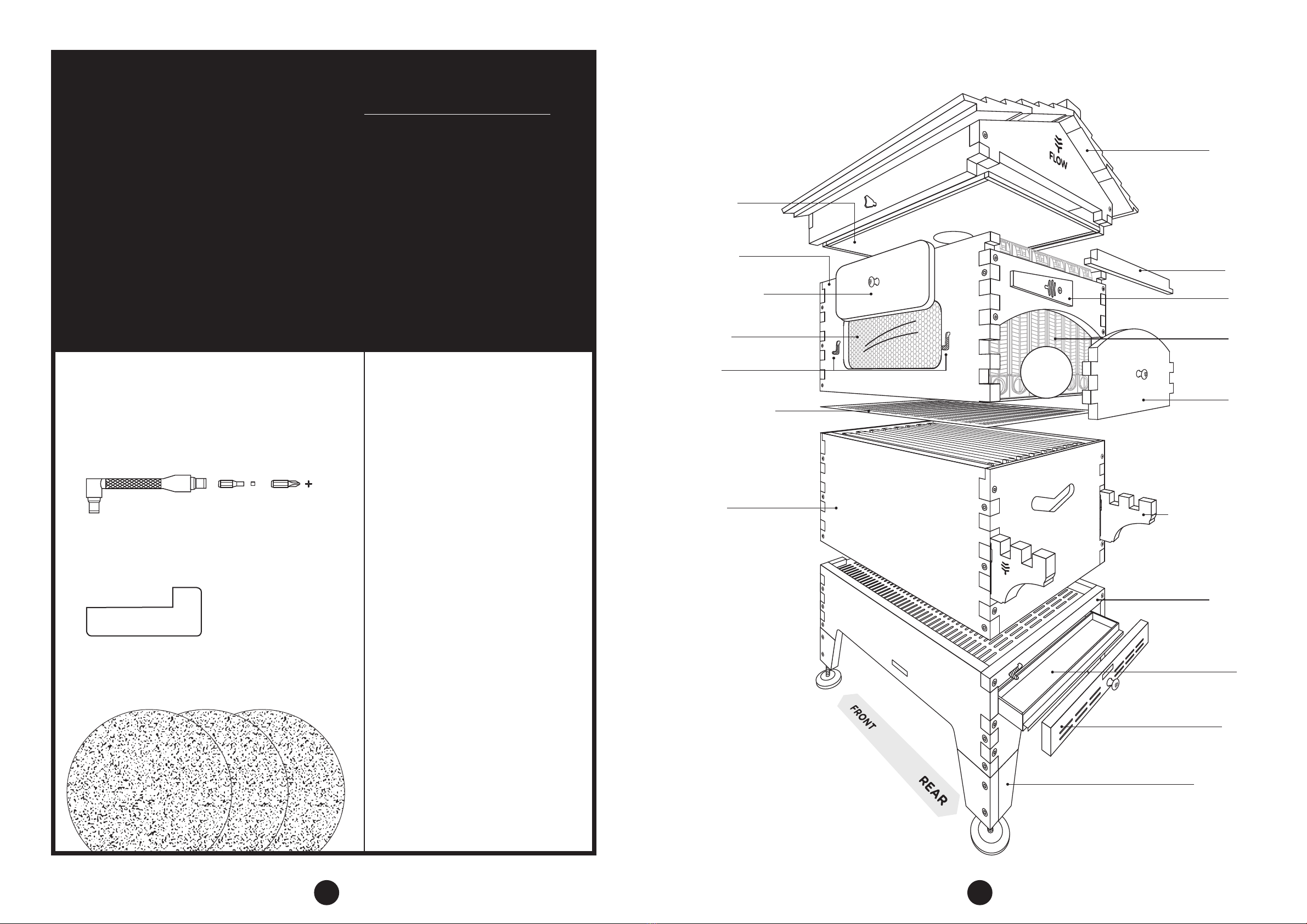
BASE SCREW PACK – ACTUAL SIZE
30 x square drive screws 8 x rail screws 2 x brass L screws 1 x brass knob screw1 x brass knob
For extra tips, check out our
assembly video at:
www.honeyflow.com/assembly
The landing
board has a
downward
slope when
fitted
The bottom rail will
slope toward the
front
The rails form a shelf
on their top edges

16 17
1. Dry fit one narrow and one wide timber leg bracket
cover to the metal leg corner bracket as shown.
2. Line up the two pilot holes in the bracket covers with
the corresponding two holes in the metal bracket
and attach (Phillips head drive bit and Phillips head
screws).
3. Attach the bracket covers together using the two
pilots holes on the wide cover (square drive bit and
square drive screws).
4. Turn the base on its side to access the bottom four
corners.
5. Align the metal brackets with the 6 pilot holes on the
inside of the base corner and attach (Phillips head
drive bit and Phillips head screws) like shown.
6. Turn the base upside down and screw the feet into
each leg bracket.
• You can adjust the height to create the optimal
slope for harvesting, using the inbuilt spirit levels on
both the side and rear of the base. If you are on flat
ground the front two legs should be longer than the
rear to create the 3° slope required for harvesting.
ASSEMBLY
outside view inside view
LEG KIT ASSEMBLY (OPTIONAL EXTRA)
4 x metal leg corner
bracket
2 x harvesting shelf brackets
4 x timber leg
bracket cover –
narrow
4 x timber leg
bracket cover –
wide
4 x adjustable foot
PARTS
1. To fix keyhole mount to bracket: place the keyhole
mount with countersink facing outward, against the
shelf bracket and attach to the vertical edge as shown
(Phillips head screws and Phillips head driver bit).
2. Make sure the large hole on the bracket mount goes
at the bottom.
Using your harvesting shelf
1. You can attach your shelf in multiple locations at
your prefered height. Choose any two corresponding
square head screws on the brood box front (using the
assembly tool and square drive bit) and wind out the
screw approximately 1 ½turns (you may need to adjust
slightly to get the perfect fit) see diagram.
• For large jars you can even use the screws on the
rear of the base for a lower shelf, but be careful
not to overload.
• Adjust the screws so that they make a nice tight
fit. If the screws are wound out too far, the brackets
will not be as structurally secure.
2. Fit the harvesting shelf bracket over the exposed
screwhead and push down until it clicks into place.
3. When you are ready to harvest you can fit the Flow
Super rear window cover to these two brackets to
create a handy shelf which will make harvesting
honey even easier.
• These brackets are designed for easy removal.
Store inside for longevity.
PARTS
ASSEMBLY
HARVESTING SHELF ASSEMBLY
HARVESTING SHELF HARDWARE PACK – ACTUAL SIZE
4 x Phillips head screws
2 x harvesting shelf bracket keyhole mounts
LEG KIT SCREW PACK – ACTUAL SIZE
8 x square drive screws
33 x phillips head screws
Wind out the screw
approximately
1 ½turns
wide
cover
narrow
cover

18 19
TIMBER FINISHES
HOW TO USE YOUR BASE TRAY
HOW TO USE YOUR SPIRIT LEVELS
Applying a suitable wood finish will improve weather
protection and increase the life of your timber hive.
Araucaria & Paulownia: We recommend painting the
outside of the hive with a paint primer followed by a
good quality exterior grade paint.
Western Red Cedar: If you would like to preserve
the natural timber finish of your hive we recommend
applying a non-toxic, no- or low-VOC timber finish to
the outside of the hive only, along with the inside of the
door covers, swing latch and bracket covers, to minimise
expansion in wet weather.
Roof: To create a good weather seal on the roof we
recommend painting with exterior grade paint. Apply a
primer first then use two coats of paint. Apply liberally to
the joins.
The base tray provides a safe space free from bee
activity, which can be used to apply pest treatments,
such as small hive beetle traps, to the hive. You can
also use the tray to inspect debris from the hive,
giving an insight into hive health. We recommend
cleaning the base tray prior to harvesting.
The Flow Hive 2 comes with two inbuilt spirit levels
to ensure your hive is set up for optimal honey
harvesting.
You can adjust the front height of your hive to create
the optimal slope for harvesting by either attaching
the supplied footblocks or optional leg kit to the
base. The inbuilt spirit levels on both the side and rear
of the base will be centred when your hive has the
optimal 3° slope required for harvesting.
For those that don’t know how to use a spirit level,
angle the base until the spirit level bubble is between
the two marks. This sets your hive on the 3 degree
slope required for harvesting.
FLOW HIVE 2 CONFIGURATIONS
STARTING YOUR COLONY CONFIGURATION
It’s important to get your brood box humming before you
add your Flow Super. First set up your base, brood box
with frames, inner cover and roof (as shown below) while
your bees are growing in number and building comb.
You can use the inner cover plug to control bee access to
your roof while the colony is establishing.
ESTABLISHED COLONY CONFIGURATION
Add your Flow Super with Flow Frames once your colony
is strong and established. Place the queen excluder
between the brood box and Flow Super. The inner cover
is placed on top of the super. It is possible to add extra
brood boxes or supers once your colony is established
and expanding. Speak to your local beekeeping club for
regionally specific advice.
Inner
cover
Inner
cover
Roof
Roof
Brood
box
Base
Brood
box
Super
Queen
excluder
Base
3°
3°

20 21
HARVESTING CHECKLIST
The Flow Hive 2 has additional new features which make the experience of harvesting
honey even easier.
Please note: some of the steps are dierent to the original Flow Hive Classic and those in
the Flow Frame Manual.
Wear a suitable protective bee suit to minimise stings.
Check out this Flow sponsored safety pamphlet: www.accreditedfirstaid.com.au/
beekeeping-safety for an introduction to beekeeping safety and first aid.
Ensure that the hive has a 3° slope towards your honey outlets.
Your base side spirit level and rear spirit level will both be aligned when the hive has
the appropriate 3° angle. (Check out page 17 for tips on how to use your spirit levels).
Clean out your base tray prior to harvesting.
Remove pest treatments and hive debris.
Ensure that each frame you are harvesting is ready and that the bees have capped
the cells.
Look in the end frame view, if the cells are mostly full and capped with wax then it’s
a good indication the honey is ready for harvest. For more hints on capping and
harvesting visit our Beginner Beekeeping Series at: www.honeyflow.com/beginner-videos.
Attach your harvesting shelf brackets (optional) or find a suitable stand for your
honey jars.
Check each bracket is secure and fit the Flow Super rear window cover to create a shelf.
Are the collection tubes pointing the right way?
The little tongue on the end of the tube goes into the frame and blocks the honey leak
back point. If the tube is the wrong way around honey may flow back into the hive. Make
sure the tube is inserted all the way in to create a seal, you may need to wiggle the tube
to make sure it fits in correctly.
Do you have enough jars?
Each Flow Frame can hold up to 2.3L /3.2kg, (2.4qt) of honey. If you are harvesting for
the first time, it may be a good idea to start with one or two frames first to make sure
everything is setup correctly.
Have covers for your jars ready
Place a cover over your jar to keep out bees or other contaminants. Some netting,
kitchen cling wrap, cloth etc. can be used to cover the open honey jars while harvesting. Flow Hive 2 – 6 frame shown

Printed on 100% recycled paper using environmentally friendly inks.
Australian Made
Flow Hive 2 Assembly Guide
Revision: 01.20
All content copyright © 2020 Flow®
ASSEMBLY VIDEOS BEGINNER VIDEOS MEET THE BEEKEEPER
honeyflow.com/assembly honeyflow.com/beginner-videos honeyflow.com/mtb
BEE PART OF OUR COMMUNITY
For beekeeping info and assembly instructions go to: www.honeyflow.com/assembly
To keep connected join us on forum.honeyflow.com or contact info@honeyflow.com
facebook.com/flowhive twitter.com/flowhive
instagram.com/flowhive
Table of contents
Other Flow Pet Care Product manuals
Popular Pet Care Product manuals by other brands

Automated Pet Care Products
Automated Pet Care Products LITTER-ROBOT manual

Frisco
Frisco 331621 Use and care instructions

Sunbeam
Sunbeam remote trainer instruction manual

iPets
iPets PET618-1 user manual

INVISIBLE FENCE
INVISIBLE FENCE Doorman Installation and Setup Instruction

Premier Pet
Premier Pet In-Ground Add-A-Dog product manual