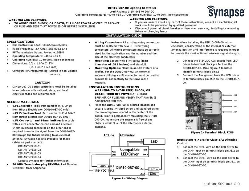
Flowmeter EASYVAC User manual

SERVICE
MANUAL
SERVICE MANUAL
EASYVAC
®
VACUUM REGULATOR
PUBLICATION CODE: MS003
EDITION: no. 6
DATE: February 2010

SERVICE
MANUAL
2 EASYVAC VACUUM REGULATOR MS003 February 2010
Contents
Warning .............................................................. 2
Your local dealer and service center.................. 3
Table of illustrations............................................ 4
Drawings ............................................................ 5
List of spare parts............................................... 8
Maintenance operations..................................... 9
Warning WARNING: DANGER INDICATION
Attention: Important indication
General information
•Read this manual carefully before using the
EASYVAC vacuum regulator.
•THIS DOCUMENT MUST BE USED TOGETHER
WITH AND IN ACCORDANCE WITH THE
OPERATOR MANUAL SUPPLIED WITH THE
PRODUCT.
•AFTER UNPACKING AND CONNECTION,
PERFORM THE FUNCTIONAL TEST DESCRIBED
IN THE CHAPTER "PERIODIC CHECKS" OF
OPERATING MANUAL MO002 ON THE DEVICE.
•USE OF INSTALLATION PROCEDURES NOT
DESCRIBED IN THE OPERATOR MANUAL
MAY REDUCE THE DEVICE’S SAFETY LEVEL.
•BEFORE EACH USE, ENSURE THAT THE
EASYVAC VACUUM REGULATOR IS
DIRECTLY OR INDIRECTLY CONNECTED TO A
COLLECTION SYSTEM FITTED WITH AN
OVERFLOW VALVE AND ANTIBACTERIAL
FILTER AND THAT THE CONNECTOR HOSES
USED CONFORM WITH THE STANDARD EN
ISO 10079-3.
•The company accepts no responsibility for the
non-observance of these service instructions,
the use of non-original spare parts and/or
repairs by unauthorised persons.
Connections
•DO NOT ALLOW OIL AND GREASE TO COME
INTO CONTACT WITH THE DEVICE.
•The vacuum supply connector is positioned on
the rear of the device and can be identified by
referring to the drawing on page 5 of
Instructions Manual MO002 (pos. 7).
Operation
•THE EASYVAC VACUUM REGULATOR MUST
ALWAYS BE USED WITH CARE AND ONLY BY
PERSONNEL WHO ARE AWARE OF THE
CONSEQUENCES OF THE ONGOING
THERAPY.
•Disconnect the vacuum supply when the unit
is not in use.
Cleaning and disinfection
DO NOT USE SOLVENTS OR ABRASIVE PRODUCTS
FOR CLEANING: THESE CAN SERIOUSLY DAMAGE
THE SURFACES OF THE EQUIPMENT AND THE
PLASTIC PARTS.
•DO NOT IMMERSE THE UNIT IN DISINFECTANT;
•DO NOT PLACE THE UNIT IN AN AUTOCLAVE;
•DO NOT USE INFLAMMABLE PRODUCTS.
IF THE EQUIPMENT IS ACCIDENTALLY CONTAMINATED
BY SUCTIONED LIQUIDS, IT MUST BE ISOLATED AND
THE NECESSARY CLEANING AND DISINFECTION
OPERATIONS CARRIED OUT BY QUALIFIED
PERSONNEL.
IF NECESSARY, STERILISE THE EASYVAC VACUUM
REGULATOR WITH A VALIDATE ETHYLENE OXIDE
STERILIZATION CYCLE (E.G. 14% EO 12 H. / 50 KPA /
37 °C).
Service
•
A
ll the modifications and repairs must only be
performed by personnel authorized by
FLOW METER S.p.A., or by hospital
technicians approved by the same company.
•Original spare parts must always be used for
the maintenance operations.
•Check the EASYVAC vacuum regulator every
three years in accordance with the chapter
“Periodic checks” of Instructions Manual
MO002.
•Due to periodic updates, the construction of
the appliance may vary. On this point,
FLOW METER guarantees the availability of
spare parts for a minimum period of 5 years
from the date of manufacture.
•Any modification to the device should only be
performed if approved by the manufacturer
and in accordance with the procedures
provided.
The device has been designed and
manufactured to meet the safety requirements
of the following standards:
•EN ISO 10079-3

SERVICE
MANUAL
3 EASYVAC VACUUM REGULATOR MS003 February 2010
Your local dealer and service center
Your local dealer and service center for FLOW METER S.p.A. products is:
TO BE FILLED IN BY THE LOCAL DEALER OR AGENT
COPYRIGHT©FLOW METER S.p.A. 1998-2010
All rights reserved. None of the information contained in this publication must be used for purposes other than the
original ones.
No part of this publication may be reproduced without the written permission of FLOW METER S.p.A.
FLOW METER S.p.A. appliances are subjected to periodic revisions to maintain and improve the production
standards, functioning and increase their reliability. For this reason, the contents of this publication may be
modified at any time without prior warning. It is possible to obtain the updated version of the present document,
when obsolete, by applying to the local dealer or agent, indicating the edition in your possession.
The equipment described in this publication is designed and manufactured by FLOW METER S.p.A. - Via del
Lino, 6 - 24040 LEVATE (Bg) – Italy – Tel. +39-035-594047 – Fax +39-035-594821 – e-mail: [email protected] -
http://www.flowmeter.it

SERVICE
MANUAL
4 EASYVAC VACUUM REGULATOR MS003 February 2010
Table of illustrations
Drawing no. TITLE PAGE
1.1 Spares for EASYVAC vacuum regulator ........................................... 5

SERVICE
MANUAL
5 EASYVAC VACUUM REGULATOR MS003 February 2010
Drawing no. 1.1

SERVICE
MANUAL
6 EASYVAC VACUUM REGULATOR MS003 February 2010
List of spare parts
Position Code Description
1 000010199 Lid for EASYVAC regulator with membrane and adjusting knob
2 000010200 I-O button switch complete with gaskets
3a 000010192 Vacuum gauge -1000 mbar for EASYVAC regulator complete with fixing support,
gaskets and protection cover
3b 000010193 Vacuum gauge -600 mbar for EASYVAC regulator complete with fixing support,
gaskets and protection cover
3c 000010194 Vacuum gauge -250 mbar for EASYVAC regulator complete with fixing support,
gaskets and protection cover

SERVICE
MANUAL
7 EASYVAC VACUUM REGULATOR MS003 February 2010
Maintenance operations
2. MAINTENANCE
2.1 INTRODUCTION
This section provides instructions for proper maintenance of the device, in order to guarantee correct functioning
and appropriate conditions of safety.
2.2 FREQUENCY OF MAINTENANCE
It is recommended that the operations specified in chapter 2.3 MAINTENANCE OPERATIONS be performed with
the following frequency:
2.3.1 REPLACEMENT OF THE I-0 BUTTON
in the case of breakage or loss of seal
2.3.2 CLEANING OF THE MEMBRANE AND BODY
every 6 months
2.3.3 REPLACEMENT OF THE LID WITH A MEMBRANE
every 24 months
2.3.4 REPLACEMENT OF THE VACUUM GAUGE
in the case of accuracy outside the tolerance levels or breakage
2.3 MAINTENANCE OPERATIONS
2.3.1 REPLACEMENT OF THE I-0 BUTTON
If the I-0 closing tap shows signs of leakage or is damaged, the entire kit (2), shown in the drawing specified in the
Table of illustrations on page 4, must be replaced.
The replacement methods are provided with the assistance of the following illustrations:
Holding the EASYVAC vacuum regulator firmly,
pull out the red button, until it is completely free of
its quick coupling, and remove it completely.
Using a screwdriver, push the green button
outwards, until it is completely removed from the
vacuum regulator.

SERVICE
MANUAL
8 EASYVAC VACUUM REGULATOR MS003 February 2010
Maintenance operations
Replace the I-0 buttons group, complete with the
relative sealing gaskets with caps. Spread a light
layer of lubricant over all sealing elements of a
new I-0 tap, using oxygen-compatible products
(e.g. FOMBLIN YNX).
Insert the green button on the left-hand side of the
EASYVAC vacuum regulator, ensuring it is turned
with the indication “I” towards the front. The rear
slot of the button must fit into the relative coupling
inside the body of the vacuum regulator itself.
Insert the red button on the right-hand side of the
EASYVAC vacuum regulator, ensuring it is turned
with the indication “0” towards the front. The rear
slot of the button must fit into the relative coupling
inside the body of the vacuum regulator itself.
Keeping the green button pressed down, push
down until the red button clicks fully into place.
Move several times in both directions in order to
lubricate the gasket housing completely and check
that the I-0 switch moves correctly. Perform the
functional checks required and indicated in the
operating manual Mo_002 of the EASYVAC
device before use.
WARNING: DO NOT USE OIL TO LUBRICATE THE PARTS.
2.3.2 CLEANING OF THE MEMBRANE AND THE BODY
The vacuum pressure membrane and the one inside the body of the EASYVAC vacuum regulator should be
cleaned periodically, to ensure the device keeps working properly.
The cleaning methods are shown with the assistance of the following illustrations:

SERVICE
MANUAL
9 EASYVAC VACUUM REGULATOR MS003 February 2010
Maintenance operations
Unscrew the lid, complete with the regulating knob
and the membrane, remove from the vacuum
regulator body and check that the inside surfaces
have not been accidentally contaminated by the
aspired liquids. If this is the case, perform the
operations indicated in the chapter “Warning” on
page 2 before continuing with the subsequent
phases.
Thoroughly clean the entire surface of the
membrane, using a soft cotton cloth dampened
with ethyl alcohol diluted to 60% in water.
Thoroughly clean the entire internal surface of the
body of the vacuum regulator, using a soft cotton
cloth dampened with ethyl alcohol diluted to 60%
in water.
Reattach the lid, complete with the regulating knob
and the membrane, onto the body of the vacuum
regulator, tightening it manually for as long as
resistance between the two parts can be felt.
Perform the functional checks required and
indicated in the operating manual Mo_002 of the
EASYVAC device before use.
2.3.3 REPLACEMENT OF THE LID WITH MEMBRANE
In order to ensure correct functioning of the EASYVAC vacuum regulator, the lid (1), complete with the silicone
membrane as shown in the drawing specified in the Table of illustrations on page 4, should be periodically
replaced. This is due to deterioration of elasticity of the membrane, which could interfere with stable and safe
regulation of the suction value set on the device.
The replacement operations are the same as those described in paragraph 2.3.2 above.

SERVICE
MANUAL
10 EASYVAC VACUUM REGULATOR MS003 February 2010
Maintenance operations
2.3.4 REPLACEMENT OF THE VACUUM GAUGE
If the periodic checks on the accuracy value of the vacuum gauge indicated in the operating manual of the
EASYVAC device shows this value falls outside the tolerance levels or in the case of accidental damage to the
vacuum gauges, they must be replaced, as specified in the Table of illustrations on page 4.
WARNING: REPLACE THE VACUUM GAUGES USING ONLY ORIGINAL SPARE PARTS WITH THE
SAME FULL-SCALE VALUE AS THE ONES BEING REPLACED.
The replacement methods are shown with the assistance of the following illustrations:
Use a TORX screwdriver of suitable dimensions to
unscrew the two screws on the rear lid. After removing the lid, take the vacuum gauge out
of the body of the regulator, pulling it outwards,
ensuring it is moved at a right angle to the body.

SERVICE
MANUAL
11 EASYVAC VACUUM REGULATOR MS003 February 2010
Maintenance operations
Screw the block back onto the vacuum gauge,
complete with the relative sealing gaskets, for as
long as slight resistance between the two parts
can be felt. Tighten for another ¼ turn, positioning
the surfaces in alignment with the metal coupling
of the vacuum gauge.
Carefully insert the vacuum gauge unit back into the
body, aligning the vacuum gauge holder block guides
with those on the body of the EASYVAC vacuum
regulator, pushing it right in. Be careful to ensure the
sealing gasket remains inserted in the block, to avoid
damage to it and a consequent loss of vacuum.
Reposition the lid and fix it in place with the two
screws by using a TORX screwdriver of suitable
dimensions. Perform the functional checks
required and indicated in the operating manual
Mo_002 of the EASYVAC device before use.
Table of contents

