manuals.online logo
Brands
  1. Home
  2. •
  3. Brands
  4. •
  5. Sealey
  6. •
  7. Controllers
  8. •
  9. Sealey SGA4.V2 User manual

Sealey SGA4.V2 User manual

instructions for
ACETYLENE REGULATOR
model no: SGA4.V2
Thank you for purchasing a Sealey product. Manufactured to a high standard, this product will, if used according to these
instructions, and properly maintained, give you years of trouble free performance.
IMPORTANT: PLEASE READ THESE INSTRUCTIONS CAREFULLY. NOTE THE SAFE OPERATIONAL REQUIREMENTS, WARNINGS & CAUTIONS. USE
THE PRODUCT CORRECTLY AND WITH CARE FOR THE PURPOSE FOR WHICH IT IS INTENDED. FAILURE TO DO SO MAY CAUSE DAMAGE AND/OR
PERSONAL INJURY AND WILL INVALIDATE THE WARRANTY. KEEP THESE INSTRUCTIONS SAFE FOR FUTURE USE.
1. SAFETY INSTRUCTIONS
9Always have a re extinguisher nearby.
8never use acetylene gas to blow soot or dirt from your clothes.
8DO NOT wear ragged clothes, as sparks can ignite the ragged or loose ends.
9 Secure cylinders to cart, wall or post to prevent them from falling.
9 All cylinders should be used and stored in an upright position.
8 Never drop or strike a cylinder. DO NOT use cylinders that have been dented.
9 Cylinder caps should be used when storing or moving cylinders.
9 Empty cylinders should be kept in specied areas and clearly marked “EMPTY”.
8 Never use oil or grease on any inlet connections, outlet connections or cylinder valves.
9 Examine hoses for cuts, burns or worn areas before each use. Also inspect ttings for damage. If any damage is found, replace
immediately.
9Keep all threads and unions clean and free from oil, dirt or grease.
8never apply oil or grease to any thread.
9for safety advice regarding gas bottles refer to the supplier of the bottles.
9make sure the bottle key is in place at all times so that in the event of an emergency the cylinder valve can be turned off quickly.
9 Check all joints weekly to make sure there are no leaks. LEAKING HOSES CAN KILL.
9 Remember at all times RED = ACETYLENE “A”
BLUE = OXYGEN “O”
9Acetylene ttings have a reverse, left-handed thread.
9 This regulator has no user-serviceable parts. All repairs/calibrations must only be undertaken by a BCGA approved service agent.
9 In case of backre or ashback immediately turn off all cylinders.
2. INTRODUCTION
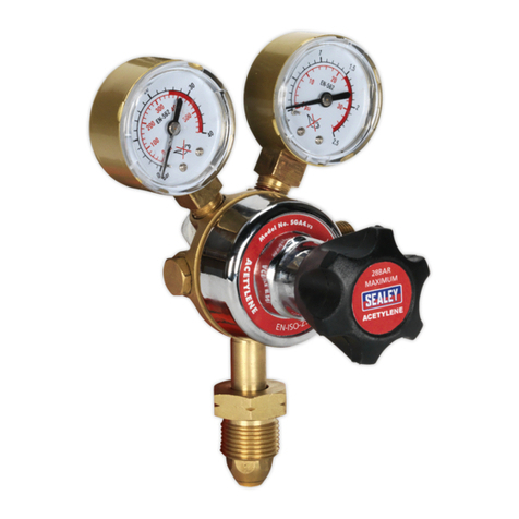
twin gauge regulator to BS EN 2503,2009 complete with bull nose adaptor and 3/8” BSP hose union. Displays bottle pressure and working
pressure for Acetylene gas. This type of regulator is intended to control the ow of acetylene gas in an oxyacetylene gas welding & cutting set-
up and should be used for no other purpose and with no other gas. The person using this regulator should be fully trained in all aspects of gas
welding and cutting including setting up, operation and safety procedures.
3. SET UP
NOTE: PRESSURE REGULATORS SHOULD BE TREATED AS PRECISION INSTRUMENTS AND SHOULD NOT BE JARRED OR
KNOCKED.
WARNING! DANGER OF EXPLOSION. All parts which come into contact with acetylene, including hands and tools, must be free from
oil or grease.
3.1. Function of the regulator.
3.1.1. Fitted to the outlet of the gas cylinder valve, the pressure regulator reduces the pressure of the gas from cylinder pressure to the
constant lower pressure required for the operation of the equipment. Pressure reduction within the regulator occurs in a single stage.
3.2. Preparing the cylinder.
3.2.1. Make sure that the cylinder to be used is safe and properly secured as noted in the safety precautions.
3.2.2. Whilst standing to one side “crack” the cylinder valve. “Cracking” is to quickly open and close the valve allowing gas to escape and
clear the valve of any foreign bodies.
WARNING! If grease or oil is found, cease use of cylinder immediately and contact your gas supplier.
3.3. Attaching the regulator.
3.3.1. Ensure the inlet lter is in place and is not blocked or contaminated.
If an ‘0’ ring is tted to the inlet, check for damage and replace if necessary with an ‘0’ ring recommended by the regulator
manufacturer. Do not use any form of jointing paste or tape between regulator and cylinder valve. Before attaching the regulator wipe
the tting with a clean dry cloth. Screw the union at the base of the regulator to the cylinder by hand. Ensure that the gauges are
correctly orientated so as to be seen properly by the operator. The regulator to cylinder tting has a reverse left handed thread. To
tighten turn anticlockwise. A wrench should be used to ensure tight connections.
sGA4.V2 | Issue 1(L) 15/04/16
Original Language Version
© Jack Sealey Limited
Refer to
Instructions
Warning
Explosive
Material
Wear
Protective
Clothing
Wear Welding
Mask
Wear
Protective
Gloves
Wear
Safety
Footwear
3.3.2. Close the regulator by turning the adjusting knob anti-clockwise to relieve the pressure on the diaphragm before opening the cylinder
valve. If this is not done, pressure from the cylinder can damage the diaphragm and render the regulator inoperative.
3.3.3. The cylinder valve-to-regulator connection should be checked for leaks using an approved leak detection spray or water and soap
solution. Stand so that the cylinder valve is between you and the regulator. Slowly open the cylinder valve.
3.4. Connecting a ashback arrestor.
3.4.1. According to safety regulations, when regulators are used with acetylene, it is compulsory to use a ashback arrestor. This should
be connected directly to the gas outlet on the regulator as shown below and the gas hose should then be tted to the ashback
arrestor. The ash back arrestor should be colour coded RED for ACETYLENE and has to be tted the right way round. It will have
the direction of ow marked on it. Follow the instructions provided with the arrestor. The arrestor will have reverse threaded unions
which have to be turned anticlockwise to attach them.
3.5. Connecting a hose.
NOTE: New hoses contain a preservative talc which must be blown out with compressed air before use.
3.5.1. Connect a hose coded RED for ACETYLENE to the ashback arrestor as shown below. Tighten nut securely with wrench. The nut
will have a reverse thread which will have to be turned anticlockwise to attach it. If any sign of oil or grease is found, discontinue use
immediately.
3.5.2. Prior to attaching the torch blow out the hose to eliminate any particles or debris. Perform this on the hose in a well ventilated area,
otherwise you may create conditions for re or explosion.
a) Turn the regulator adjusting screw slowly clockwise until the outlet gauge registers 5psi and acetylene begins to pass through
hose.
b) Allow the acetylene to ow for approximately 10 seconds to purge the hose.
High pressure gauge
indicates pressure
in acetylene cylinder
High pressure gauge
indicates pressure of
acetylene delivered to
to rch
Max outlet
pressure1.5 Bar
Max inlet
pressure 20 Bar
To increase pressure
turn clockwise
To decrease pressure
turn anticlockwise
Gas in from cylinder
(tting has left hand thread)
4. OPERATION
4.1. Ensure that the regulator is closed by turning the adjusting knob anti-clockwise to relieve the pressure on the diaphragm before
opening the cylinder valve. If this is not done, pressure from the cylinder can damage the diaphragm and render the regulator
inoperative.
4.2. Slowly open the acetylene cylinder valve. As you do so the high pressure gauge (left hand) will register the cylinder pressure.
4.3. Slowly open the regulator by turning the adjusting knob clockwise. As you do so the outlet pressure gauge (right hand) will register
the outlet pressure of gas being fed to the torch. Adjust the pressure according to the size of nozzle in use and the thickness of the
material to be cut or welded. The manufacturer of the torch will normally supply a data chart to refer to.
4.4. Shutting down process. On completion close the cylinder valve.
4.5. Drain gas from the regulator and hose by opening the appropriate acetylene control valve on the torch for a few seconds. Ensure
adequate ventilation when doing this.
4.6. Close the regulator by turning the adjusting knob anti-clockwise.
sGA4.V2 | Issue 1(L) 15/04/16
Original Language Version
© Jack Sealey Limited
5. MAINTENANCE
5.1. Each time the equipment is used.
5.1.1. The regulator should be visually examined to determine its suitability for service. If any of the following conditions apply the
regulator should be withdrawn from service:
5.1.2. There should be no contamination with oil or grease or solvents.
5.1.3. The inlet and outlet connections should be free from grit and other particles.
5.1.4. There should be no damage to threads, sealing surfaces, or seals.
5.1.5. There should be no visible damage to the pressure gauges or dials and indicators under the pressure gauge windows.
5.1.6. When assembled to an acetylene cylinder with ashback arrestor and hose attached all joints shall be leak tested.
5.2. Annually.
5.2.1. The gauge should be tested under known conditions to determine that it is still working properly.
5.3. Replacement/refurbishment intervals.
5.3.1. Subject to conditions of use the regulator should be replaced with a new, repaired, or service exchange unit every 5 years or in
accordance with the manufacturers recommendations. If regulators are repaired or refurbished this should be done in accordance
with the BCGA (British Compressed Gas Association) Code of practice CP7.
NOTE: It is our policy to continually improve products and as such we reserve the right to alter data, specications and component parts without prior notice.
IMPORTANT: No liability is accepted for incorrect use of this product.
WARRANTY: Guarantee is 12 months from purchase date, proof of which will be required for any claim.
sole UK Distributor, Sealey Group.
Kempson Way, Suffolk Business Park,
Bury St. Edmunds, Suffolk.
iP32 7AR
www.sealey.co.uk
sales@sealey.co.uk
01284 757500
01284 703534
Web
Environmental Protection
recycle unwanted materials instead of disposing of them as waste. All tools, accessories and packaging should be sorted,
taken to a recycling centre and disposed of in a manner which is compatible with the environment.
Parts support is available for this product. To obtain a parts listing and/or diagram,
please log on to www.sealey.co.uk, email sales@sealey.co.uk or telephone 01284 757500.
sGA4.V2 | Issue 1(L) 15/04/16
Original Language Version
© Jack Sealey Limited

Other Sealey Controllers manuals

Sealey SUPERBOOST 180.V5 User manual

Sealey

Sealey SUPERBOOST 180.V5 User manual

Sealey REG/MO.V2 User manual

Sealey

Sealey REG/MO.V2 User manual

Sealey SA2FR.V3 User manual

Sealey

Sealey SA2FR.V3 User manual

Sealey POWER PRODUCTS SA106 User manual

Sealey

Sealey POWER PRODUCTS SA106 User manual

Sealey SA106 User manual

Sealey

Sealey SA106 User manual

Sealey SGA4.V2 User manual

Sealey

Sealey SGA4.V2 User manual

Sealey SUPERSTART300.V5 User manual

Sealey

Sealey SUPERSTART300.V5 User manual

Sealey SGA4 User manual

Sealey

Sealey SGA4 User manual

Sealey ECS350 User manual

Sealey

Sealey ECS350 User manual

Sealey SA4FR/38 User manual

Sealey

Sealey SA4FR/38 User manual

Sealey START800 User manual

Sealey

Sealey START800 User manual

Sealey SUPERBOOST 140.V4 User manual

Sealey

Sealey SUPERBOOST 140.V4 User manual

Sealey ECS400 User manual

Sealey

Sealey ECS400 User manual

Sealey SA2001 User manual

Sealey

Sealey SA2001 User manual

Sealey SUPERSTART220.V3 User manual

Sealey

Sealey SUPERSTART220.V3 User manual

Sealey SA2FR.V3 User manual

Sealey

Sealey SA2FR.V3 User manual

Sealey REG/MO.V2 User manual

Sealey

Sealey REG/MO.V2 User manual

Sealey ARD01 User manual

Sealey

Sealey ARD01 User manual

Sealey REG/MM.V2 User manual

Sealey

Sealey REG/MM.V2 User manual

Sealey SA206 User manual

Sealey

Sealey SA206 User manual

Sealey ELECTROSTART E/START3012 User manual

Sealey

Sealey ELECTROSTART E/START3012 User manual

Sealey SGA40 User manual

Sealey

Sealey SGA40 User manual

Sealey SGA3.V2 User manual

Sealey

Sealey SGA3.V2 User manual

Sealey RS22 User manual

Sealey

Sealey RS22 User manual

Popular Controllers manuals by other brands

Honeywell Pneumatic Controls Engineering guide

Honeywell

Honeywell Pneumatic Controls Engineering guide

Bard ECU Series Supplemental instructions

Bard

Bard ECU Series Supplemental instructions

Immergas 3.021523 quick guide

Immergas

Immergas 3.021523 quick guide

AES e-DIAGNOSTIC quick start guide

AES

AES e-DIAGNOSTIC quick start guide

YOKOGAWA YS1700 Tech note

YOKOGAWA

YOKOGAWA YS1700 Tech note

J.R. Merritt Controls MPFC Adjustment instructions

J.R. Merritt Controls

J.R. Merritt Controls MPFC Adjustment instructions

HP StorageWorks ESL E Series quick start guide

HP

HP StorageWorks ESL E Series quick start guide

LITELINE DazzLED LED-RGB-24-PC quick start guide

LITELINE

LITELINE DazzLED LED-RGB-24-PC quick start guide

HP MSM720 specification

HP

HP MSM720 specification

Flex-a-Lite 31163 installation instructions

Flex-a-Lite

Flex-a-Lite 31163 installation instructions

KING UC1000 user manual

KING

KING UC1000 user manual

Netech MiniSim 330 instruction manual

Netech

Netech MiniSim 330 instruction manual

Nectar Sun S user manual

Nectar

Nectar Sun S user manual

Prolon C1050 Series Specifications and Operational Guide

Prolon

Prolon C1050 Series Specifications and Operational Guide

MachMotion Apollo III 1000 Series manual

MachMotion

MachMotion Apollo III 1000 Series manual

Made mPAD user guide

Made

Made mPAD user guide

Canarm MC Series installation guide

Canarm

Canarm MC Series installation guide

Leviton RZCZ1 installation instructions

Leviton

Leviton RZCZ1 installation instructions

manuals.online logo
manuals.online logoBrands
  • About & Mission
  • Contact us
  • Privacy Policy
  • Terms and Conditions

Copyright 2025 Manuals.Online. All Rights Reserved.