Fluid Concepts Rear Bimini User manual

Axis Rear Bimini
2015-2019 (all models)
Instruction Manual
Congratulations on your purchase of one of the premier tow boat products in the industry! This
bimini top is designed to provide you years of service and satisfaction with the proper care and instal-
lation. Please read these instructions carefully. If at any time you have a question about the bimini
or installation, please call (480) 609-1182 and ask for technical assistance.
*****Important Safety Precautions*****
Please Read
This Bimini is designed to used at tow boat speeds only. Do not trailer boat while deployed.•
Do not allow passengers to hang on or pull on rear frame extension wihile deployed.•
Ensure all bolts and hardware are tightened before each use.•
Do not use bimini if hardware is missing or broken or if the bimini shows any type of stress (cracks, broken welds, etc).•
When operating or towing boat with bimini installed, be aware of low bridges, waterways, powerlines, trees, or other low objects•
that may come into contact with bimini top.
Do not store surf boards or other objects on top of bimini.•
Failure to adhere to these safety warnings and guidelines will void warranty and may cause personal injury.•
Fluid Concepts
134 E. Broadway Rd. #101
Mesa, AZ 85210
(480) 609-1182
www.fluidconcepts.net
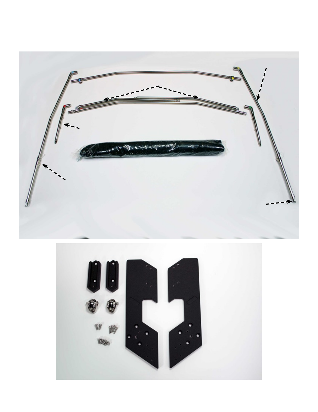
Unpack Contents:
Carefully unpack contents of boxes. Find a suitable area to lay the parts out and assemble (wood shop
table or other soft work area). Please identify parts using the list below. Now is a good time to inspect
parts for damage from shipping.
Fluid Concepts Page 2
Rear Frame
Front Frame Assembly
Canvas and Boot
Folding Arm Assembly
Hinges
Front Shorts w/Snaps
Ball End Fittings
Stanchions
Fig 1
Fig 2
Tools:
1. Hex keys x 3: 1/8” (or 3mm*), 5/32”, 1/4”
2. 9/16” wrench
2. Thread Lock (Loctite Blue) ---optional
*depending on components used in assembly
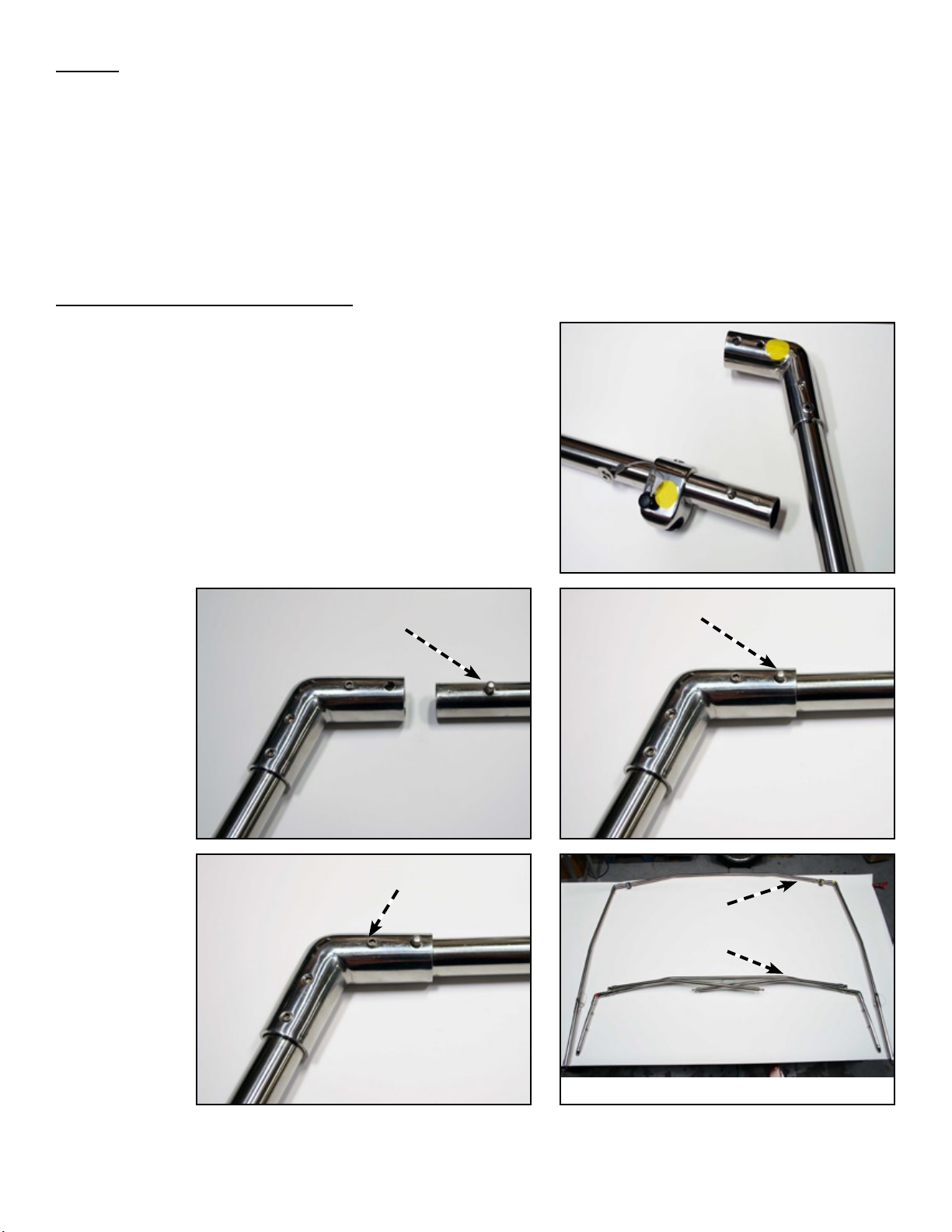
Bimini Frame Pre-Assembly:
Step 1: Identify each frame piece according to Fig-1.
CornerFittingsareidentiedbyacolors(4total)Fig-3.
Find corresponding tube piece with same color and insert
into Corner Fitting Fig-4A. Push until Snap Button clicks
into locating hole on Corner Fitting. Make sure pin is fully
engaged in hole as shown in Fig-4B. Repeat for the 3
remaining corners. Note: Colors may not be the same as
shown in picures.
Step 2: Tighten all set screws adjacent to Snap Button tube
locks. Fig-5A At this point you should have two separate
frames assembled (front frame and rear frame) as shown in
Fig-5B.
Fluid Concepts Page 3
Fig 3
Fig 4A Fig 4B
Fig 5A Fig 5B
Snap Button Snap Button
fully engaged
Set Screw
Rear Frame
Front Frame

Bracket Pre-Assembly:
Step 1: Mount Tube-Stops to top of Mounting Brackets.
Position the Tube-Stops with groove opening pointing towards
top of bracket as seen in Fig-6 and Fig-7. Secure with (4)
1/4-20atheadscrews.
NOTE: Some brackets may have auxilary sets of threaded
holes located in close proximity to desired mounting holes.
Do not use these holes! Please use holes closest to
the edge of Mounting Brackets.
Step 2: Mount Quick-Release Ball End Fittings to
Mounting Brackets.Positionttingsexactlyasshown
in Fig-6 and Fig-8. Thettingsshouldmirroreachother
withthetwistpinslocatedontheupperhalfofthetting.
Use mounting holes located closest to the edge of the part.
Secure with the 10-24 x 3/4” socket head cap screws. Do not
overtighten! D-Ring on each part should be located toward
edge of part. Fig-8
NOTE:Thequick-releasettingsaremirroredparts.There
is a left and right. There is also a top and bottom. The larger
opening (and D-Ring Twist Pin) are located toward the top of
thetting.Thisallowsthebiminiballendtoslidedownward
to lock into place. Fluid Concepts Page 4
Fig 4
Fig 8
NOTICE:
Pay special attention to position
of each component in relation
to brackets and mounting holes.
Brackets and components mirror
each other.
10-24 x 3/4” (x 4)
1/4-20 x 5/8” (x 4)
Fig 6
Mounting Bracket
Starboard/left
Mounting Bracket
Port/right
Tube-Stop
Quick-Release Ball End
Fitting
Fig 7
Tube-Stop
Groove Opening
Quick-Release
D-Ring Twist Pin
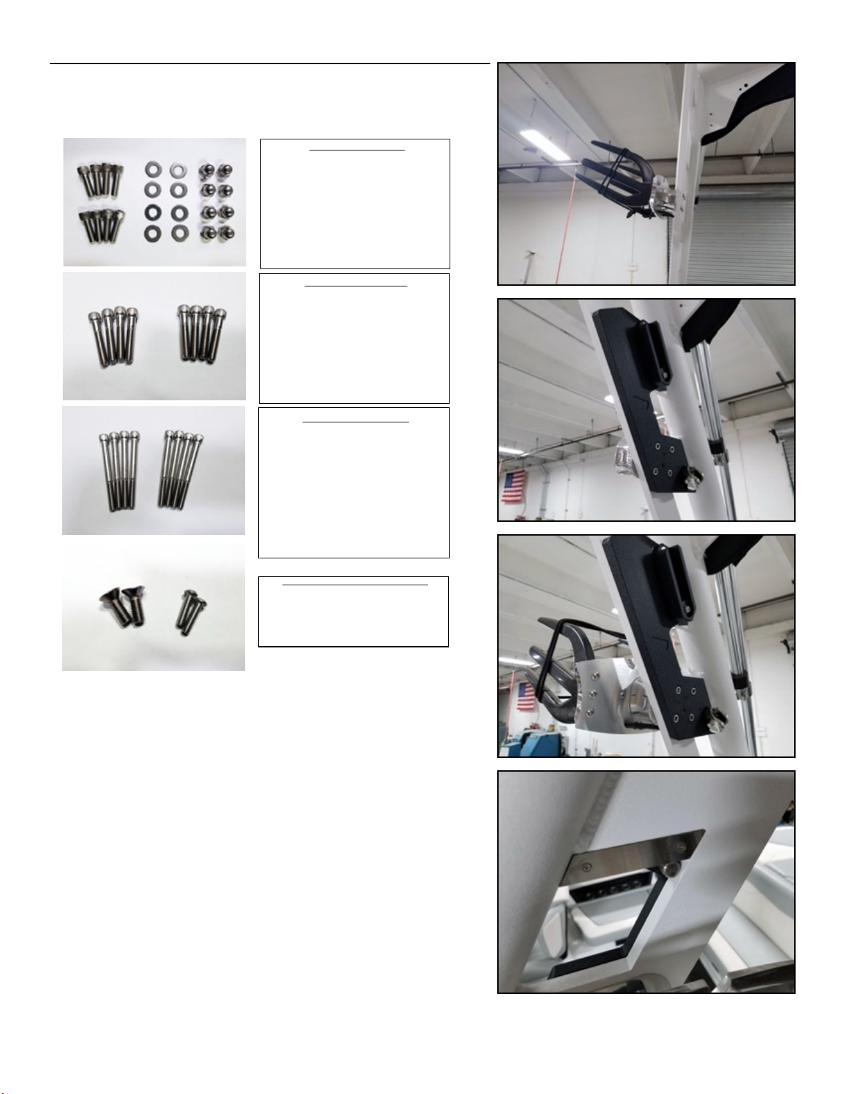
Installing Brackets and Bimini Frame to Tower:
Step 1: Determine Mounting Bolt Kit. Depending on the
board rack options on your boat, you will need one of the 3
available bolt kits:
Step 2:Inourexamplewehavexedracks,sowe’llbe
usingthexedrackmountingkit.We’llalsobeusingablack
mounting bracket on a white tower for picture contrast.
Fig-9 Remove both boardracks and replace existing mounting
hardware with new hardware supplied with your bimini kit.
Set brackets on tower using new hardware, then carefully
slide rack spacer over the screws. Fig-10 Next, carefully hold
rack into position while tightening screws. Fig-11
HINT: it may be easier to do two screws rst, then
come back and insert remaining screws. Depending on
agility, have a second person hold boardrack in place
while the other tightens screws. Notice pin on back of
mounting bracket sits in corner of machined window of tower.
Fig-12 Once everything is in place, tighten all screws using
1/4” hex key/wrench.
Fluid Concepts Page 5
Swivel Rack Mounting Kit
OBSOLETE (standard kit)
Fixed Rack Mounting Kit
Standard Mount Kit
Standard Mounting Kit:
Use when mounting bimini brackets to tower with
no boardracks.
***Replaces obselete kit as seen below***
PART: AXS-EB-STD
Description: (8) 5/16-18 x 1-3/8” SHCS SS, (8)
5/16 SS Washers, (8) 5/16-18 Acorn Nuts
Fixed Rack Mounting Kit:
Use when mounting bimini brackets to tower and
OEM fixed boardracks are mounted in top position.
This kit replaces stock screws.
PART: AXS-EB-FMK
Description: (8) 5/16-18 x 1-3/4” SHCS SS
Swivel Rack Mounting Kit:
Use when attaching bimini brackets to tower and
OEM Swivel boardracks are mounted in top posi-
tion. This kit replaces stock screws.
NOTE: The use of the swivel rack feature will be lost when
bimini is deployed. We suggest moving swivel racks into the
lower position to maintain full functionality.
PART: AXS-EB-SMK
Description: (8) 5/16-18 x 3-1/4” SHCS SS
OBSOLETE Standard Mounting Kit:
Please call (480) 609-1182 for free upgrade to the
updated kit above. New part: AXS-EB-STD
Fig 9
Fig 10
Fig 11
Fig 12

Step 3: Install Front Frame Assembly. Set frame ends
into grooves of the tube-stops. Fig-13 Make sure Stanchions
and Stanchion Hinges are facing towards the rear of the
boat.Theframemayneedtobeexedslightlytogetinto
the grooves. This is normal. Aligned Eye Ends with mounting
threaded hole and use supplied 1/4” button-head socket
screw to fasten. Fig-14A Tighten both fasteners. The front
frame should look like Fig-14B
Step 4: Install Rear Frame Assembly: Make sure Quick-
Release Ball End Fittings are ready to accept frame Ball Ends.
Turn the D-Ring Twist Pin until groove is open. Fig-13 With
Bimini Hinge Pins pointing upward on Rear Frame, insert one
endofRearFrameballttingintotheQuick-Releasetting
and slide downward to set in place. Do the same for the
opposite side. Lock in place by turning D-Ring Twist Pin until
groove is closed. Fig-16 The rear bimini frame should look
like this. Fig-17
Fluid Concepts Page 6
Fig 13
Fig 14A Fig 14B
Fig 16
Fig 15
Fig 17
D-Ring Groove
Open
D-Ring Groove-
Closed
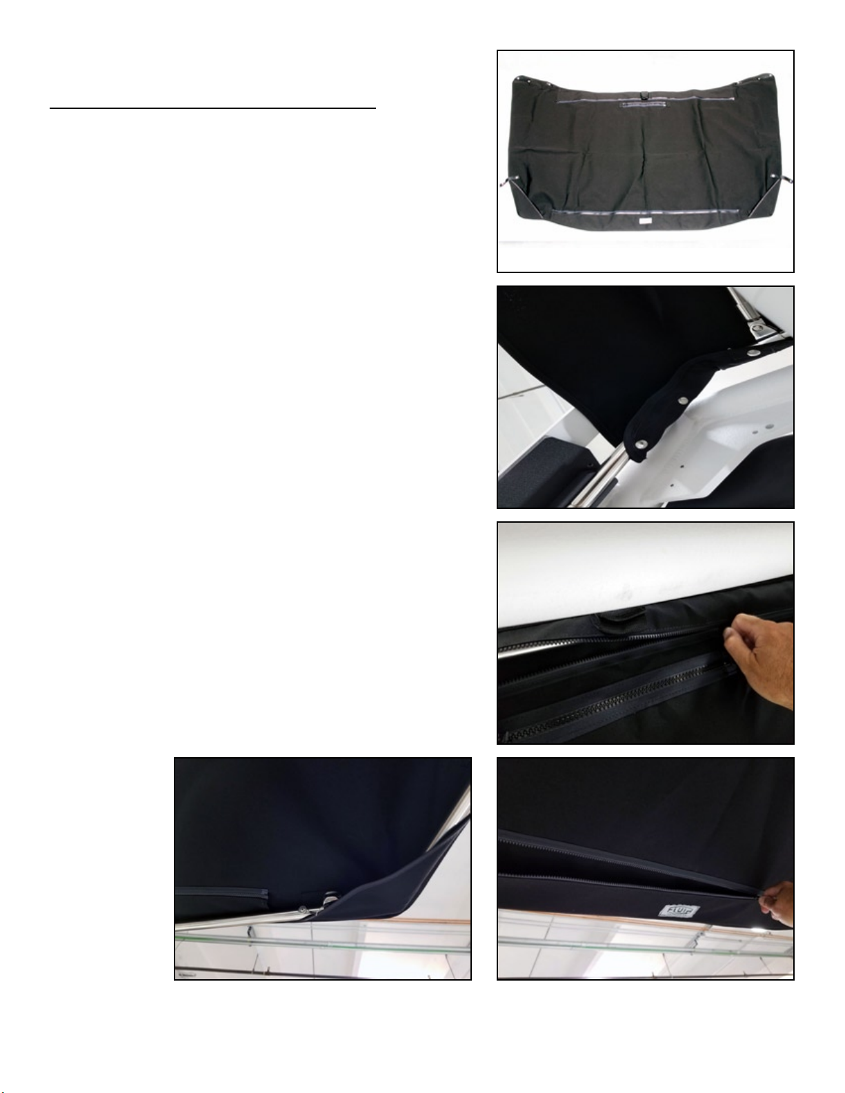
Installing Bimini Canvas on Frame:
Step 1: Locate Underside of Canvas. To locate underside
ofcanvas,layonatsurfaceandlocatesidewithcorner
pockets visible (stainless snaps will also be facing in same
direction). Fig-18
Step 2: Wrap canvas corner around Front Frame Corners as
shown in picture. Snap canvas to frame using the 3 snaps.
Repeat for opposite side. Underside of Canvas should be
facingoorofboat.MakesuretheStancionsarepointed
towards the center of the boat. Canvas can then drape over
the frame at this point. Fig-19
Step 3: Place zipper pocket around Front Frame and close
zipper. Fig-20
Step 4: Lift frame up and position corners of Canvas over
the rear corners of the Bimini Frame. The frame should be
hanging in air at this point, with the Stanchions still pointing
towards the center/rear of the boat. Fig-21
Step 5: Again, using rear zipper pocket, secure canvas
around rear frame and zip. See instructions below to setup
bimini for use. Fig-22
Fluid Concepts Page 7
Fig 18
Fig 19
Fig 20
Fig 22Fig 21

Instructions for Use:
Stowing Bimini:
NOTE: At this point your bimini should be loosely hanging
fromrearoftower.Inthenextsteps,we’llshowyouhowto
stow bimini, then deploy.
Step 1: Stow bimini. Fold Stanchions toward center of
boat, then secure to underside of Front Frame using velcro
strap. Fig-23
Step 2: Pull Pins out of Hinges on Rear Frame to allow the
frame to collapse. Fig-24 HINT: Occaisonally there may
be tension on the bimini frame which makes the pins
dicult to pull out. If so, try slightly pulling the bimini
frame upwards and towards the center of the boat (at
the hinge) while pulling pins. This should alleviate and
tension in hinge pins. Allow frame to fold, then manuever
Rear Frame to sit just behind the Front Frame. Place loose
canvas over the top and wrap around both frames. Fig-25
Step 3: Using frame clips, clip folded frame together. Fig-
26 The canvas and the frame clips should hold the frame in
place long enough to get the Bimini Boot over the canvas.
HINT: Depending on boat and speaker package, it may
be easier to use a small strap or have someone help
hold frame for next step.
Step 4: Install Bimini Boot. Pull boot over top of frame
and canvas. Zip to secure. Fig-27 The bimini should be
secure and stowed at this point.
NOTE: While towing boat when bimini is in the stow position,
it is a good idea to push dangling hinge pins into hole. Be
sure to remember to remove them before deploying bimini!
Fig 23
Fig 24
Fig 25
Fig 26 Fig 27
Fluid Concepts Page 8
White Nylon Frame
Clips

Deploying Bimini:
Step 1: Remove Bimini Boot and remove Bimini Frame Clips.
Allow frame to rest below tower. Fig-28
Step 2: Straighten rear frame. Install Hinge Pins. Make
sure Hinge Pins are fully inserted. Fig-29
Step 3: Bimini frame should be loosely hanging from rear
of tower (same position as the last step on page 7). Check
bimini canvas and make sure it is in postion before moving on
to next step. The pockets should be around the rear frame,
with the canvas in a loose setup postion. Fig-30
Step 4: Remove Stanchions from velcro strap. Swing one
Stanchion towards rear of boat and secure into the Ball End
Fitting on Rear Frame. Secure with Pin. Fig-31 Repeat for
other side. HINT: sometimes the bimini canvas may
be tight and prevent the stanchion end from sliding
into position on the rear ttings. It may help to pull
down on the frame to pre-tension the canvas so the
stanchions can be locked into place.
Step 5: Tighten the side skirts by wrapping strap around
frame and snapping. Fig-32 That’sit.Checkbiminitoproper
tandmakesureframefeelssecure.Centerzipperpocket
is for easier access to tow rope spool in center of tower.
Reverse Process to Stow.
Do not hang from bimini frame. This will
cause premature wear and may damage
canvas or frame.
Fig 28
Fig 29
Fig 30
Fig 32
Fluid Concepts Page 9
Fig 31

Care and Maintenance
Periodic maintenance: Wipe down surfaces with damp cloth. Soap and water may used to clean.
Avoid harsh chemicals as they will damage the painted/polished surfaces. Canvas may be washed with
water and vacuumed.
5 Year Limited Warranty
Weoera5YearWarrantyonourproductsalongwitha30daymoney-backguarantee.Ifyouarenotsatisedwithourproducts
in any way, return the item and we will refund your money!
Warranty Information
Fluid Concepts L.L.C. (Fluid) warrants to the original purchaser that this product will be free from defects in material and
workmanshipundernormaluseforaperiodofve(5)yearsfromdateoforiginalpurchasefromanauthorizedFluiddealer.See
exclusionsforspecicitemsnotcoveredorwithlimitedwarranty.Shouldrepairbenecessaryunderthiswarrantyforanyreason
due to a manufacturing defect or malfunction during the warranty period, Fluid will repair or replace (at its discretion) the defective
product with equivalent product at no charge. Discontinued products may be replaced with equivalent products. Any applicable
implied warranties are limited in duration to a period of the express warranty as provided herein beginning with the date of the
original purchase at retail, and no warranties, whether express or implied, shall apply to this product thereafter. This warranty is
limited to defects in material and workmanship, and it does not apply to loss of damage due to accident, misuse or negligence, or
any cause occurring after delivery to the original purchaser.
Warranty Claims
Defective merchandise must be returned to your local authorized Fluid Dealer for warranty issues. To locate an Authorized Dealer
please email or call Fluid Concepts direct. If the return of defective merchandise is necessary, call Fluid at (800) 284-6615 to
obtain a Return Authorization (RA) number. Package all defective items in the original container or in a suitable package that will
prevent shipping damage, and return to:
Fluid Concepts
134 E. Broadway Rd. #101
Mesa, AZ 85210
Include a dated proof-of-purchase from an Authorized Dealer. Warranty expiration on items returned without proof-of-purchase
will be determined from the manufacturing date code. Freight must be prepaid; items received freight collect will be refused.
Failure to follow these steps may void your warranty. Non-defective items received will be returned freight collect. Any warranty
questions can be directed to the Fluid Concepts at (480) 609-1182.
Warranty Exclusions:
The following items have a limited warranty:
1.Rubber components (1 year)
2.Stretch cord (1 year)
3.Chromenish(1year)
4.Anodizednish(3years)
5.Powdercoatednish(2years)
This warranty is valid only if the product is used for the purpose for which it was designed.
Fluid Warranty does not cover:
•Damageresultingfromnegligence,misuse,oraccident
•Itemsphysicallydamagedduetoabuse
•Freightdamageormishandling
•Itemspreviouslyrepairedbyanyunauthorizedrepairfacility
•Speakerswithsiliconcaulkingortapeusedforgasket/sealingmaterial
•Itemsreturnedbyunauthorizedindividualsordealers
•Returnshippingofnon-defectiveitems
•Speakersdamagedduetoamplierclippingordistortionorincorrectsignals
•ThecostofshippingproducttoFluidConcepts
•Installationslipsincludingscrewdriverholesinspeakersurroundsandscratchedsurfaces
•Normalwear-and-tearfromuse,storage,andtransportation
•Damagecausedbyexposuretowaterand/orexcessiveheat
•Itemsdamagedfromcross-threadingfastenersorimproperinstallationtoolsandtechniques.
•Damageresultingfromitemscomingintocontactwithobjectssuchasbridges,otherboats,etc.
Fluid Concepts Page 10
Table of contents
Popular Boating Equipment manuals by other brands

Old Town
Old Town Saranac Seat Kit instructions

SLEIPNER MOTOR AS
SLEIPNER MOTOR AS Side-Power Series installation manual

MAX PROP
MAX PROP Easy installation instructions

Vetus
Vetus BOW1254DE Operation manual and installation instructions

MINN KOTA
MINN KOTA RIPTIDE ST user manual

SPORT MARINE TECHNOLOGIES
SPORT MARINE TECHNOLOGIES SE Sport 400 manual

Classic Accessories
Classic Accessories Silver Max 87504 instructions

Quick
Quick GP Series Installation and user manual

Classic Accessories
Classic Accessories StormPro Instructions & Care

Nucraft
Nucraft CraftLander MH-V25108 Assembly & instruction manual

ProFurl
ProFurl B29S installation manual

Uflex
Uflex ULTRAFLEX T71FC Installation and maintenance manual


