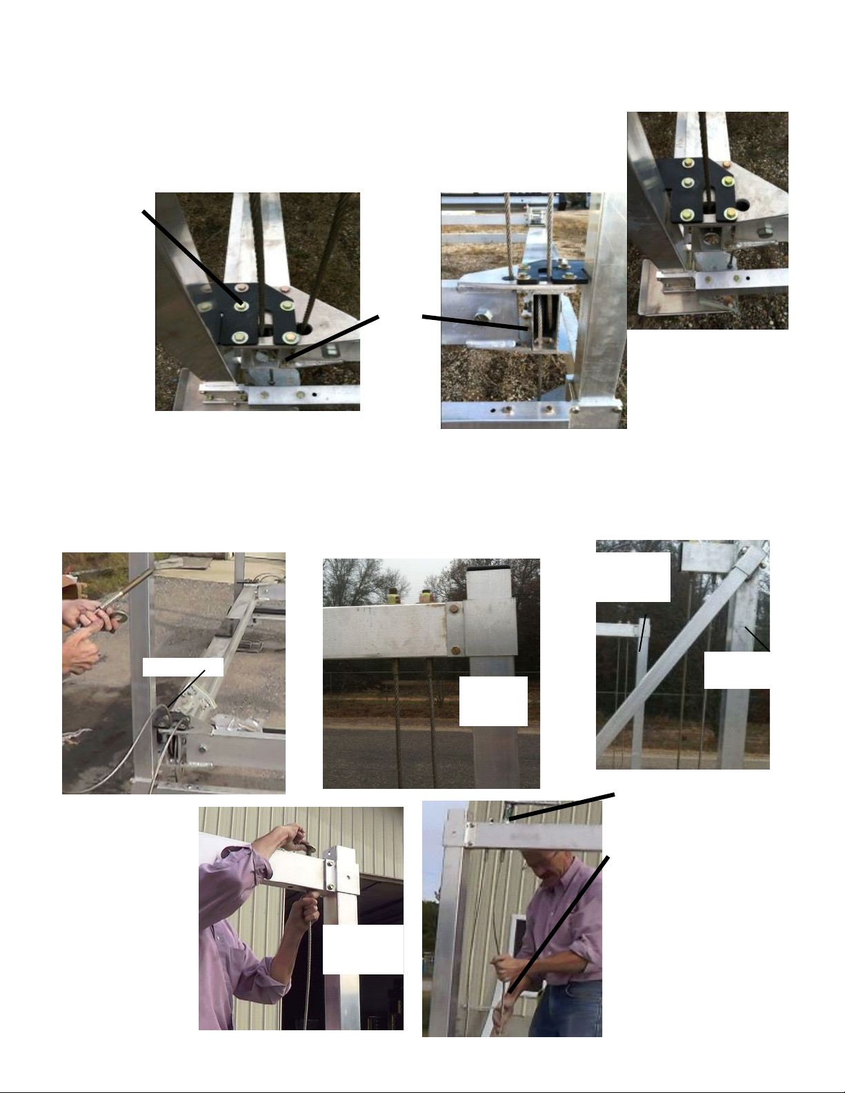
(16) The Cradle Tube Left and Right will have one
cable coming out of it. Each end will have a welded
connection plate. The larger plate will be on top of the
tube. Place the Cradle Tubes so the angle portion of the
connection plate is facing the inside of the hoist. Match
the top larger hole with the holes on the twin beam on
all four corners.
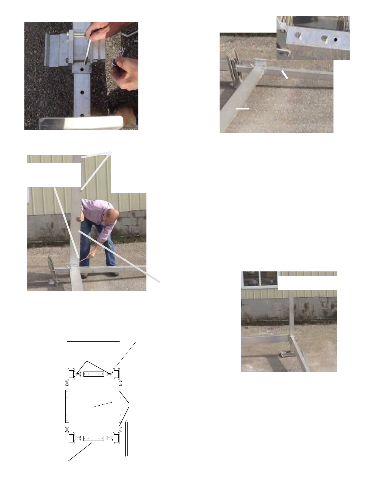
(17) Next, starting with the Non-Winch front corner you will
need to pull the cable coming from the Twin Beams through the
corresponding hole in the Right Cradle Tube. The cable with a
long threaded end coming out of the front Twin Beam will be
pulled through to attach to the Upper Cable Tube. The cable
coming out of the Cradle Tube Right with the short threaded
end will go down to the /4” galvanized plate
fastened to the lower frame.
View of
on-
Winch
Column
front
corner.
Pull up
Cradle Tube
Left
Cradle Tube
Right
Rear
Front
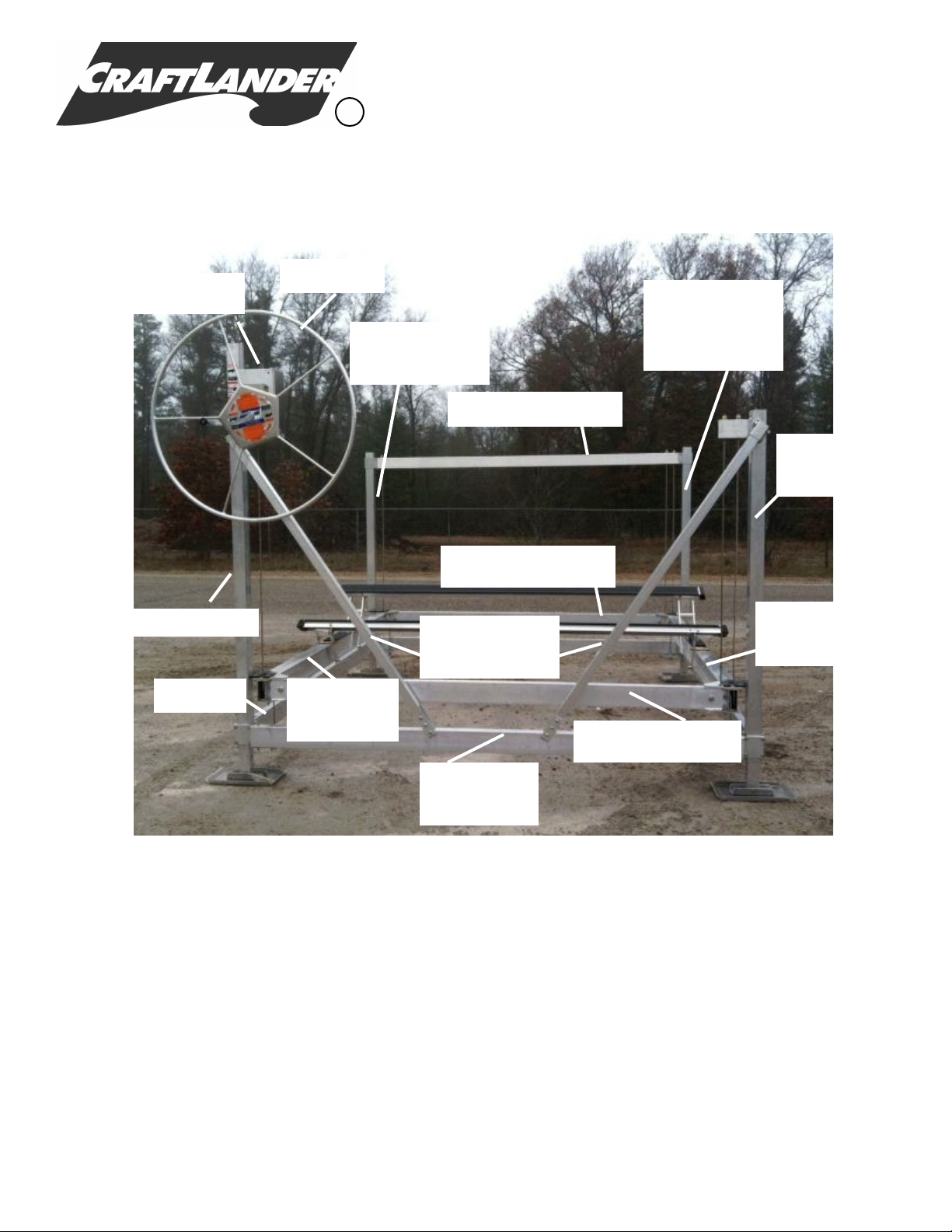
(15) The front Twin Beam will be
the one with one cable coming out
of it. This will be placed in the
front of the hoist. The end of the
beam that has the cable without a
fitting will go on the Winch
corner. The rear Twin Beam will
have two cables coming out of it
and this will be placed at the rear
of the hoist.
Front
Rear
Two Cables
Twin Beam:
4”x4 3/8”x 3 /4” long on V25 08
4”x5 /2”x 3 /4” long on V35 08 or V45 08
4”x5 /2”x 9 /4” long on V45 4
4”x5 /2”x 25 /4” long on V35 20 or V45 20
(16) The Cradle Tube Left and Right will have one
cable coming out of it. Each end will have a welded
connection plate. The larger plate will be on top of the
tube. Place the Cradle Tubes so the angle portion of the
connection plate is facing the inside of the hoist. Match
the top larger hole with the holes on the twin beam on
all four corners.
Cradle Tube (both sides):
3/4”x4”x 00” long on V25
2”x5”x 2” long on V35 & V45
(17) Next, starting with the Non-Winch front corner you will
need to pull the cable coming from the Twin Beams through the
corresponding hole in the Right Cradle Tube. The cable with a
long threaded end coming out of the front Twin Beam will be
pulled through to attach to the Upper Cable Tube. The cable
coming out of the Cradle Tube Right with the short threaded
end will go down to the /4” galvanized plate
fastened to the lower frame.
View of
on-
Winch
Column
front
corner.
Pull up
(18) Continue on to the
Winch corner. The Cable
coming out of the end of
the front Twin Beam will
not have a threaded end.
This end will be connected
to the Winch Box in a later
step. The cable coming out
of the Left Cradle Tube
will go down to be attached
to the lower frame.
Cradle Tube
Left
Cradle Tube
Right
Rear
Front
(15) The front Twin Beam will be
the one with one cable coming out
of it. This will be placed in the
front of the hoist. The end of the
beam that has the cable without a
fitting will go on the Winch
corner. The rear Twin Beam will
have two cables coming out of it
and this will be placed at the rear
of the hoist.
Twin Beam:
4”x4 3/8”x 3 /4” long on V25 08
4”x5 /2”x 3 /4” long on V35 08 or V45 08
4”x5 /2”x 9 /4” long on V45 4
4”x5 /2”x 25 /4” long on V35 20 or V45 20
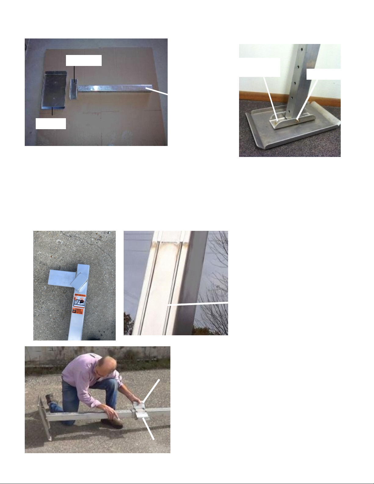
Note that the beams should
be placed with the holes on
the bottom facing the inside
of the hoist as shown above.
Page#7