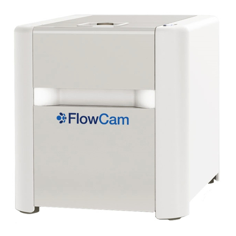
Fluid Imaging Technologies FlowCAM User manual

FlowCAM®Manual
Version 3.0
September 2011
Fluid Imaging Technologies, Inc.
65 Forest Falls Drive ∙ Yarmouth, Maine 04096 USA
Tel: 207.846.6100 ∙ Fax: 207.846.6110

- 2 -

- 3 -
Preface ........................................................................................................................................................................................5
FlowCAM Safety........................................................................................................................................................................6
Standard Factory Limited Warranty.......................................................................................................................................7
SECTION ONE-INTRODUCTION.........................................................................................................................................8
The Scope of this Manual..........................................................................................................................................................8
SECTION TWO-MODES OF OPERATION.......................................................................................................................13
Understanding AutoImage Mode...........................................................................................................................................13
Understanding Trigger Mode (Fluorescence & Scatter)......................................................................................................16
SECTION THREE-INSTRUMENT SETUP ........................................................................................................................19
Instrument Setup .....................................................................................................................................................................19
Model C50 & C51 Peristaltic Pump.......................................................................................................................................23
Model C70 & C71 Syringe Pump...........................................................................................................................................27
SECTION FOUR-VISUALSPREADSHEET........................................................................................................................38
Main Window...........................................................................................................................................................................48
File Menu..............................................................................................................................................................................48
Edit Menu .............................................................................................................................................................................52
Analyze Menu.......................................................................................................................................................................53
Setup Menu...........................................................................................................................................................................54
Context….........................................................................................................................................................................54
Setup Menu… Pump…....................................................................................................................................................70
Setup Menu… Setup and Focus… (F6) ...........................................................................................................................72
AutoImage Mode (No Save)… (F7).................................................................................................................................77
Trigger Mode Setup… (F8)..............................................................................................................................................78
Trigger Mode (No Save)… (F9).......................................................................................................................................78
File Processing Mode (No Save)…..................................................................................................................................78
Magnification…...............................................................................................................................................................78
Tools Menu...........................................................................................................................................................................79
Preferences Menu..................................................................................................................................................................81
Help Menu ............................................................................................................................................................................84
View Window...........................................................................................................................................................................87
Tool Bar................................................................................................................................................................................88
Status Bar..............................................................................................................................................................................89
View Window… File Menu..................................................................................................................................................90
View Window… Edit Menu .................................................................................................................................................91
View Window… Sort Menu .................................................................................................................................................92
View Window… Filter Menu ...............................................................................................................................................93
View Window… Statistics Menu..........................................................................................................................................97
View Window… Show Menu...............................................................................................................................................98
Right Click Popup Menu ....................................................................................................................................................100
Keyboard Commands..........................................................................................................................................................100

- 4 -
Library Window ....................................................................................................................................................................101
Library Window… File Menu ............................................................................................................................................102
Library Window… Edit Menu............................................................................................................................................104
Library Window… Sort Menu............................................................................................................................................105
Library Window… Show Menu .........................................................................................................................................106
Right Click Popup Menu ....................................................................................................................................................106
Keyboard Commands..........................................................................................................................................................106
Classification Window...........................................................................................................................................................107
Classification Window… File Menu ..................................................................................................................................108
Classification Window… Edit Menu..................................................................................................................................110
Classification Window… Classes Menu.............................................................................................................................111
Classification Window… Operation Menu.........................................................................................................................113
Classification Window… Sort Menu..................................................................................................................................113
Classification Window… Filter ..........................................................................................................................................113
Classification Window… Statistics Menu ..........................................................................................................................114
Classification Window… Show Menu................................................................................................................................114
Right Click Popup Menu ....................................................................................................................................................114
Keyboard Commands..........................................................................................................................................................115
Appendix I: Flow Cells and Tubing Specifications.............................................................................................................116
Appendix II: Glossary of Particle Properties & Other Terms...........................................................................................117
Appendix III: How VisualSpreadsheet Determines Parts/Million and Particles/mL......................................................120
Appendix IV: FlowCAM Trigger Mode Guide...................................................................................................................122
Appendix V: FlowCAM Calibration Verification Procedure............................................................................................125
FlowCAM Size & Count Calibration Verification Report.................................................................................................129
Appendix VI: FlowCAM Quick Start Guide.......................................................................................................................130
Appendix VII: Standard FlowCAM Hardware Configurations........................................................................................133
Appendix VIII: Frequently Asked Questions (FAQ)..........................................................................................................136
Index .......................................................................................................................................................................................141
Notes........................................................................................................................................................................................145

- 5 -
Thank You
Fluid Imaging Technologies, Inc. would like to thank you for making the important decision to purchase
the FlowCAM®system. We are committed to manufacturing quality products and providing
unsurpassed customer service.
Copyright Notice
FlowCAM®and VisualSpreadsheet®are registered trademarks of Fluid Imaging Technologies, Inc.
Microsoft Windows and Microsoft Excel are trademarks of Microsoft Corporation. All other trademarks
used within this manual are hereby acknowledged.
Copyright 2011 Fluid Imaging Technologies, Inc. All Rights Reserved Worldwide.
Fluid Imaging Technologies customers may reproduce this manual in printed form provided the content
remains unchanged. Reproduction or republication of any portion of this manual for any other purpose
is prohibited without the expressed written consent of Fluid Imaging Technologies, Inc.
Manual Information
FlowCAM®Manual. Version 3.0, September 2011. VisualSpreadsheet®3.0, Portable, Open Benchtop,
Benchtop Models. Manual edited by Benjamin Spaulding, Laboratory Manager.

- 6 -
·Before operating the system, read the manual carefully to prevent damage to
humans, animals, integrated devices, and connected devices. Always follow local
safety rules.
·Do not look directly into the laser beam. Do not look at any laser light directly or
through optical lenses. Wear appropriate safety glasses to prevent laser light from
entering the eye, even reflections from any surface. When changing optical
components, always disable (via VisualSpreadsheet) the laser.
·Beware of electrical shock hazard. To prevent the risk of electrical shock or fire,
always disconnect the AC/DC power before disconnecting cables or wiring
connectors. Electrical units should not be operated in hazardous environments.
Do not touch any damaged, non-isolated electrical parts.
·This instrument may be harmed by mishandling the flow chamber and/or removing
the photomultiplier tube from its mounting bracket and/or exposing it to direct
room light (while the unit is plugged in and has power). Improper software
settings will not cause damage.
·There are no user serviceable parts inside this unit. Do not attempt any repairs
yourself. Doing so will void your Standard Factory Limited Warranty. Should
your FlowCAM require service, please contact Fluid Imaging Technologies, Inc.
for additional instructions. This product must not be disposed of in normal
household waste. Contact Fluid Imaging Technologies for proper disposal
instructions.

- 7 -
Standard Factory Limited Warranty
Fluid Imaging Technologies, Inc. (“Seller”) warrants that the FlowCAM®product (“Product”)
purchased by you (“Customer”) shall be free from material defects in workmanship and material for a
period of one (1) year from the date of shipment by the Seller (the “Limited Warranty”); provided,
however, that the Limited Warranty does not cover any consumables (flow cells, flow cell holders, or
tubing) or third party manufactured/customer purchased items incorporated in the Product. For Service
and Spare/Replacement parts, the Seller also warrants the services we perform and the spare and
replacement parts we install, for a period of one (1) year from the date of performance of such services
and the date of installation of the spare or replacement parts, respectively. Customer understands and
agrees that the Limited Warranty shall only apply if Customer has used the Product in accordance with
all specifications, documentation, and other information provided to Customer by Seller.
Customer’s sole and exclusive remedy and Seller’s entire liability under the Limited Warranty shall be
(i) at Seller’s option, repair or replacement of the Product or any defective Product components
(including any labor or other services related thereto), and (ii) all shipping costs related to the repair or
replacement of the Product or any defective Product components for both on-site and off-site repairs and
replacements.
Any Product or Product components returned to Seller must have prior approval and must reference a
Return Material Authorization (RMA) number issued by Seller. In the event Seller determines that the
entire Product must be returned to Seller for repair or replacement, such Product must be shipped in its
original shipping container to assure adequate protection during transit. If the original shipping
container is not available, a new shipping container may be purchased from Fluid Imaging
Technologies, Inc. at an additional cost.
The foregoing Limited Warranty is in lieu of all other warranties, written or oral, express or implied,
including, but not limited to, a warranty of merchantability, non-infringement, title or fitness for a
particular purpose. In no event shall seller be liable for any direct, indirect, consequential, punitive,
incidental or any other damages of any kind whatsoever, arising out of or relating to the product, any
product components, any specifications, documentation or other information provided to Customer in
connection with the product, or the limited warrant set forth herein, even if Seller has been advised of, or
otherwise should have been aware of, the possibility of such damages, and regardless of the legal theory
or basis for such claim.

- 8 -
Introduction
The Scope of this Manual
Throughout the pages of this manual, you will learn how to set up and operate your FlowCAM®. This
manual is intended to be used with both the Benchtop and Portable Series of FlowCAM models. Minor
differences exist between the models and as such, will not affect the usefulness of this manual.
Additionally, this manual is written to address and describe the configuration of a model VS-IV
FlowCAM (AutoImaging, two Fluorescence Trigger channels, and one Scatter Trigger channel)
equipped with a syringe pump. It must be recognized that some configurations of the FlowCAM system
may not contain fluorescence, light scatter triggering/measurement capability, or a different type of
pump. Please disregard any sections of this manual which do not directly apply to your particular
instrument.
Benchtop B3 Series FlowCAM
Benchtop B2 Series FlowCAM Portable Series FlowCAM

- 9 -
The FlowCAM®
The FlowCAM®is an integrated system for rapidly analyzing particles in a moving fluid. The
instrument combines selective capabilities of flow cytometry, microscopy, and fluorescence detection.
The FlowCAM automatically counts, images, and analyzes the particles or cells in a sample or a
continuous flow. Best of all, a FlowCAM can be customized to accommodate almost any environment
or application.
Originally developed for oceanographic investigations of organisms and particles in seawater, the
FlowCAM provides the user with the capability to rapidly evaluate particulate matter in fluids. The
instrument and software provides the user with tools to quickly and efficiently meet challenges that
previously required multiple instruments and many hours of tedious work to complete. Your FlowCAM
has the following features and capabilities:
·High-Speed Digital Imaging
·Particle Size, Count, and Shape
·Real-Time Bulk and Individual Particle Analysis
·The Combined Benefits of Multiple Instruments
·Compact and Durable Packaging
·Ability to Image Particles 2 µm to 3 mm in Diameter
·Fluorescence Detection Providing Additional Selectivity
·Scatter Detection for Low Particle Concentrations
Basic Overview of the FlowCAM
In the FlowCAM system, sample is drawn into the flow chamber by a pump. Using the laser in Trigger
Mode, the photomultiplier tubes (PMTs) and scatter detector monitor the fluorescence and light scatter
of the passing particles. When a particle passing through the laser fan has sufficient fluorescence or
laser light scatter, the camera is triggered to take an image of the field of view. The fluorescence
value(s) and/or scatter detection value are then saved by VisualSpreadsheet (in addition to all other
particle properties). The computer, digital signal processor, and trigger circuitry work together to
initiate, retrieve and process images of the field of view. Groups of pixels that represent particles are
then “segmented” out of each raw image and saved as a separate collage image (along with all
associated parameter measurements). The process described above is similar when using AutoImage
Mode, except the camera is set to capture raw images at a user defined interval.

- 10 -
Advanced Overview of the FlowCAM
The FlowCAM architecture can be divided into three distinct systems:
·Optics
·Fluidics
·Electronics
Optics
Figure 1 is a block diagram of the FlowCAM architecture. The following
section explains the operation of the components illustrated when using laser
dependent Fluorescence and/or Scatter Trigger modes.
As the particles are drawn into the flow chamber they pass through a “laser
fan” that has been generated by the laser and a lens. Fluorescence which
results from this illumination is passed back through the objective and the
partial mirror. This light then passes through a system of optical filters and
mirrors. The shorter wavelengths of green to orange are reflected by a mirror
to the 500-600 nm fluorescence detector. Longer wavelength light passes
through another filter to the 600-700 nm fluorescence detector. Finally, a scatter detector is located at
the end of the optical path (in the same cube as the flash LED) to detect any disturbances in the laser
light.
If either the fluorescence or scatter detector receives a strong enough signal, indicating the presence of a
particle of interest, the flash LED is turned on for a very short interval. This light is then imaged with
the objective onto the camera. A patented depth of focus enhancer stretches out the focus of the
objective, thus enhancing the resolution of particle images.
Fluidics
Sample fluid is drawn through the Flow chamber for analysis by a syringe
pump and then deposited into an outflow collection. FlowCAM’s unique
flow chamber is a key component to this system. Unlike conventional flow
cytometers, the FlowCAM does not use a sheath fluid for hydrodynamic
focusing (laminar flow). Instead, it uses a flow chamber with a variable size
cross section. A complete list of the standard flow cell dimensions
recommended for each objective is available in Appendix I.
The appropriate flow chamber size is chosen by considering the following
interdependent factors:
·Objective Magnification
·Size and Size Range of Particles Under Study
·Desired Flow Rate
·Viscosity of the Fluid

- 11 -
While the optimum values for each of these factors for a given application is usually determined through
application development, a “starting point” is easily determined merely by looking at the particle size
range under study.
Electronics
The Digital Signal Processor (DSP) and trigger circuitry are central to the
operation of the instrument. They provide a critical interface between the
software and all other components of the FlowCAM. This complex circuit
board measures the parameters of the fluorescence and/or light scatter signals
and provides these parameters to the processor upon request. It also provides
trigger signals which are generated when passing particles are of sufficient
fluorescence or within previously set light scatter parameters. While in
AutoImage mode, this board generates the appropriate signals to the camera
and image processor.
Figure 1. FlowCAM Block Diagram

- 12 -
Anatomy of a FlowCAM (Open Bench Top)
The first step in understanding the potential of the instrument is learning the components of the
FlowCAM assembly. Figure 2 is a picture of one version of the VS-IV Open Bench Top Model (this
unit can AutoImage, Scatter Trigger, has two Fluorescence Trigger channels and has a color camera.)
While this particular unit pictured below uses a 532 nm laser, and is set up to detect red (>650 nm) and
orange (575 nm) fluorescence, the principles are the same for other laser and filter configurations. An
example of such an alternative configuration would be an instrument that uses a 488 nm (blue) laser for
excitation, a green emission (525 nm) Filter set, and images with a high resolution black and white
camera. Additionally most models of the FlowCAM come equipped with a syringe pump.
Figure 2. VS-IV Open Bench Top Series FlowCAM
A. Digital Camera
B. Photo-Multiplier Tubes (Channels 1 & 2)
C. Unit and Laser Power Switches
D. Computer
E. Digital Signal Processsor (DSP)
F. Pump (peristaltic)
G. Laser Cube (laser is hidden from view)
H. Scatter Detector (located behind cube)
I. Flash LED (located on edge of cube)
J. Fine Focus Adjustment
K. Microscope Objective Cube
L. Flow Cell Holder Mount
M. X & Y-Axis Adjustment Knobs
N. Course Adjustment Screw
O. LED Collimator or Diffuser Lens cube
D
E
A
F
C
B
I
J K M N O
G
H
L

- 13 -
Modes of Operation - AutoImage Mode & Trigger Mode
Understanding AutoImage Mode (Including File Reprocessing Mode)
·AutoImage Mode defined
·Particle Concentration Calculation: AutoImage Mode
·Setup & Focus (Camera Image Preview)
·AutoImage Mode (No Save)
·AutoImage Mode
·File Processing Mode (No Save)
·File Processing Mode
Understanding Trigger Mode (Fluorescence & Scatter)
·Trigger Mode defined
·Particle Concentration Calculation: Trigger Mode
·Trigger Mode Setup
·Trigger Mode (No Save)
·Trigger Mode: Fluorescence (Channels 1 & 2) and Laser Light Scatter
·Important Information Regarding Trigger Mode
Understanding AutoImage Mode
AutoImage Mode Definition
AutoImage Mode is an image analysis mode in which the FlowCAM captures images of the moving
fluid at a regular, user-defined interval (Frames Per Second or FPS). This mode is used when
processing samples with high particle concentrations. The total number of particles imaged is a function
of the following:
·concentration and properties of particles in the sample fluid
·camera field of view (FOV) dimensions
·total number of field of view images (taken at a regular, user-defined interval) that were analyzed
The volume analyzed is determined based on flow cell dimensions and the concentration of particles is
reported at the end of the run. In other words, the concentration of particles in the sample fluid is
determined by dividing the total number of particles imaged (counted) by the total volume of sample
fluid imaged. The concentration is automatically calculated using the following information:

- 14 -
·total number of particles imaged (counted)
·field of view dimensions (based on a calibration factor for microns/pixel)
·depth and width of the flow cell
·total number of frames that were collected
Fluid Volume for AutoImage Mode
The value for Fluid Volume Imaged for AutoImage mode is automatically generated at the end of a run
using the method shown below under Particle Concentration Calculation. The value for “Fluid Volume
Imaged” corresponds to the actual number of milliliters that were imaged for that particular AutoImage
analysis.
Particle Concentration Calculation: AutoImage Mode
A summary of the following calculation description can be found in Appendix III. For AutoImage
Mode analysis, the method to determine particle concentration of an unconstrained camera field is as
described in the following paragraph.
There are several values that are measured by VisualSpreadsheet that are required for the calculation of
Particle Concentration (P/mL or PPM):
·Particle Count
·Area Based Diameter (ABD) of each particle
·Equivalent Spherical Diameter (ESD) of each particle
·Total number of camera images taken for the full duration of the analysis
There are also several parameters that are user defined that VisualSpreadsheet uses in the calculation:
·Acceptable range of camera view
·Flow cell depth (D) in µm
The acceptable range of camera view is dependent on the properties of the digital camera. Depending
on the model of the digital camera, the maximum and minimum number of pixels may be different than
the values used below in the example calculations. Typical values for camera pixels are 1024 x 768 and
1280 x 960. The FlowCAM will arrive with factory default settings that include the correct values for
the installed digital camera. VisualSpreadsheet determines the acceptable region within the camera’s
field of view by the following process. Note that the acceptable range of the camera can be changed or
“constrained” by the user:
Left = user-specified number (default value = 0 pixels)
Right = user-specified number (default value = 1279 pixels)
Top = user-specified number (default value = 0 pixels)
Bottom = user-specified number (default value = 959 pixels)
With these numbers specified, VisualSpreadsheetcan then determine the height and width of the
acceptable region with the following calculations:

- 15 -
Height (H) = (1 + (Bottom - Top)) x the Calibration Factor (µm per pixel)
Width (W) = (1 + (Right - Left)) x the Calibration Factor (µm per pixel)
Depth (D) = User defined value determined by the dimensions of the flow cell used during the analysis
Note: The Calibration Factor (used for H and W) is factory determined and the value set as a default
value.
The Volume per Picture is calculated as D × H × W (µm3)
VisualSpreadsheet can determine the total volume it imaged with the following calculation:
Total Volume Imaged = Number of Images Taken during the Run × Volume per Picture (µm3)
VisualSpreadsheet can calculate PPM using either the ESD or ABD measurements.
Total Volume of Particles using ESD or ABD (µm3)
PPM = ————————————————————— X 106
Total Volume Imaged (µm3)
Particle Count 1 x 10¹² (µm3)
P/mL = ———————————— X ———————
Total Volume Imaged (µm3) 1 (mL)
To locate the values used in the above calculations, from the Main window:
·For Height and Width, Setup > Context > Capture (tab) > Acceptable Region (section), to view
the total number of pixels from left to right, and from top to bottom.
·For Depth, Setup > Context > Flow Cell (tab) > Flow cell (section) for the “Flow cell depth”
value (populated from the Flow Cell Database file).
·For total number of camera images, Setup > Context > Run Summary (tab) > Images > Total.
Setup and Focus (Camera Image Preview)
The Setup and Focus window (Setup Menu or Hotkey = F6) is used to adjust the focus, camera, and
context settings of the FlowCAM while sample is present in a flowcell. By default, in AutoImage
Mode, the camera images the field of view at a regular interval-determined by the AutoImage Rate
setting in frames per second (Setup > Context > Camera > Timing [section]). The resulting images are
displayed in the Setup and Focus window. This window can be used for centering the flow cell, or for
“real time” particle monitoring. Note that Raw camera images shown in the Setup and Focus window
are neither captured nor saved with the following exception: before exiting Setup & Focus mode or
while paused, the last image in the viewer can be saved (this is described in more detail in Section Four).

- 16 -
AutoImage Mode (No Save)
In AutoImage Mode (No Save) (Setup Menu or Hotkey = F7), the user can view how the software will
segment the field of view raw images into the collage window. This No Save mode is an excellent tool
to test the effects of using different context settings and to make a final adjustment of the focus. This
Mode is described in more detail in Section Four.
AutoImage Mode
In AutoImage Mode (Setup Menu or Hotkey = F4), the particles in the field of view are imaged and
captured at a regular interval. The operator uses the pulldown menu “Analyze” and selects AutoImage
Mode. Images of all captured particles and their Particle Properties are stored on the hard drive along
with Summary Statistics and Calculated Values (Calculated Values include statistical information such
as Mean, Standard Deviation, etc.).
File Processing Mode (No Save)
File Processing Mode (No Save) (Setup Menu) is used to process raw images captured to disk during a
previous sample run. VisualSpreadsheet has the ability to save Raw Camera Images while running an
AutoImage or Trigger Mode analysis. If the user has selected the option to save raw camera images,
File Processing Mode can be used at a later time to reprocess these raw images. Reprocessing of these
previously collected raw images can be useful for testing the efficiency of capturing particles of interest
under different context settings. Therefore, this mode can assist the user in optimizing how particles are
captured without actually running additional sample through the unit. The results of this Mode are not
saved. This Mode is described in more detail in Section Four.
File Processing Mode
File Processing Mode (Analyze Menu) is used to process raw images captured to the hard drive during a
previous sample run. This mode functions exactly as File Processing Mode (No Save) except that the
results of this Mode are saved.
Understanding Trigger Mode (Fluorescence & Scatter)
Trigger Mode Definition
Trigger Mode is an image analysis mode on the FlowCAM in which the scattering of laser light is
measured and/or two photo multiplier tubes (PMT) are used to measure fluorescent particles, and those
measurements are compared against a threshold value.
When a particle passes through the laser and generates a signal that meets or exceeds one of the
threshold values, the camera is triggered to take an image. Camera triggering is thus based upon the
Threshold value. Each particle currently in the objective’s field of view will be captured in this image.
Once this raw image is captured, VisualSpreadsheet will then apply the context settings you have
previously entered to this image and process the raw image.

- 17 -
The user should use Trigger Mode when the sample contains fluorescent particles or organisms and you
want to capture only these specific particles. Additionally, use Trigger Mode if you have a very dilute
sample and you wish to ensure that you capture an image of the entire particle, rather than risk capturing
only a partial image (which can occur in AutoImage Mode).
Particle Concentration Calculation: Trigger Mode
For additional information regarding this calculation, please refer to the section “Particle Concentration
Calculation: AutoImage Mode”. In Trigger Mode, the concentration of particles in the sample fluid
imaged is a function of:
·number and properties of particles in the sample fluid
·width of the field of view
·width of the flow cell
·total volume of sample fluid that passed through the flow cell
The software will calculate the actual number of milliliters that passed through the field of view. For
Trigger Mode runs, the value for Fluid Volume is the total number of millilitres that passed through the
instrument.
Trigger Mode Setup
In Trigger Mode Setup (F8) (Setup Menu or Hotkey = F8), the user can view the rate of triggering. This
is similar to the Setup and Focus Mode described above, however, a camera image of the field of view is
captured only when the predetermined fluorescence or light scatter threshold is exceeded by a particle.
Note that before exiting this mode or while paused, the image in the viewer can be saved (this will be
described in detail in Section Four).
Trigger Mode (No Save)
In Trigger Mode (No Save) (Setup Menu or Hotkey = F9), the user can view the rate of triggering and
observe how the software will segment the field of view image into the collage window. This Mode is a
good tool to use to test the effects of using different context settings and to make a final adjustment of
the focus.
Trigger Mode: Fluorescence (Channels 1 & 2) and Laser Light Scatter
For this mode, the user chooses “Trigger Mode” from the pull down Analyze menu (Hotkey = F5).
When triggering on fluorescence, the field of view is imaged when the intensity of fluorescence of
passing particles exceeds a user set threshold. When triggering on light scatter, the field of view is
imaged when the intensity of the light scatter signal exceeds a user set threshold. Measured values are
then saved with the images (along with all other relevant statistics and particle properties).
Important Information Regarding Trigger Mode
As you attempt to optimize an analysis done in Trigger Mode, it is important to note that there are a few
factors that may affect the performance of your FlowCAM in Trigger Mode.

- 18 -
When using a FlowCAM, your objective lens does not view the entire width of the flow cell. If you are
using the FlowCAM for counting purposes, you might want to consider using a field-of-view (FOV)
flow cell - this will allow you to image the entire fluid stream. The FOV flow cells are available for
purchase from Fluid Imaging Technologies, Inc.
If you are not suspending your sample in a dense or viscous fluid, or you are not occasionally stirring the
sample in the funnel, you may get a settling effect. You may notice that as the fluid level in your funnel
decreases, particles may stick to the side of the funnel. If you see this settling effect you will want to
carefully mix the funnel contents. During an analysis you can also open the Time Series Graph (you can
view this graph in “real time” as you are running your sample). To open this graph: select Tools > Time
Series Graph. The user can display several different plots including a “Frequency Plot” (by right
clicking on the graph). If the sample is settling, you should notice a gradual decrease in the slope of the
trend line. This decrease indicates that your sample could be slowly settling out of solution.
It is possible to capture images of particles that did not trigger the laser or the PMT. This happens
because once the threshold level is met or exceeded, the camera takes a raw image, and
VisualSpreadsheet will capture all particle(s) based on your context settings. If there is more than one
particle in the raw image, VisualSpreadsheet has no way to determine which particle produced the
trigger signal. Therefore the PMT/Scatter data values are assigned to all particles within that raw image.
To avoid this situation, the user should dilute the sample to a concentration where the software is only
capturing one particle per used image.
To assist the user with determining if the test sample is too concentrated for optimal Trigger Mode
analysis, VisualSpreadsheet calculates a Particles Per Used Image value. The user can open a “Particles
Per Used Image” value display in the capture window. While in the Setup and Focus [F6] capture
window, select Show > Configure Display > and check the “show particles per used image” box. This
number should ideally be between an average value of 1.00 and 1.10 (with 1.00 being the most optimal
result). If your particles per used image value is larger than 1.10 you should continue to dilute your
sample. Note that VisualSpreadsheet can account for this dilution of the sample solution. To enter the
correct values for the dilution navigate to Setup > Context > Fluidics > Sample Dilution > and enable
“The sample fluid was diluted or concentrated” > enter the correct ratio.
The rate at which you set your pump can also influence both the image quality and number of particles
you will collect. If the pump speed is too fast, you may find that the particle that caused the triggering
event is already out of the objective’s field of view before the camera can take an image. This means
that you may have zero particles being captured in your raw images. Slowing down the pump speed can
help alleviate this problem. Remember that flow rate is a function of pump speed, pump tubing
diameter, pump tubing elasticity, sample viscosity, and flow cell dimensions. The most effective way to
determine the flow rate for a particular configuration is to measure the time required to pull a known
volume of sample through a fully primed system. Post-analysis, users can open a .lst file from a
previous run and correct the flow cell dimensions, fluid volume, etc. At this point, the data may be
saved as another .lst file under a different name. This process is typically done if values have been
entered incorrectly or additional sample was added to the funnel during the run, etc.

- 19 -
Instrument Setup
·Initial Setup and Instrument Configuration
·Optimizing the Field of View and Focus
·Maintenance and Shutting Down
Initial Setup and Instrument Configuration
Note that a basic “Quick Start” procedure (Appendix VI) and a list of standard Hardware configurations
(Appendix VII) can be found at the end of this manual.
Power Configuration for a Portable FlowCAM
Due to the portable nature of this model of the FlowCAM, it includes a power cord that will plug into a
12V power supply (for example, a power outlet in a vehicle). There are up to three other power cords
for the Portable FlowCAM. These include a standard wall outlet cord and a cord for the wireless mouse
charger. If your FlowCAM came with a USB hub, that may have be the third power cord.
The Wireless Mouse and Keyboard Charger included with the FlowCAM can only be used in a
120V/60Hz power receptacle.
Power Configuration for an Open Benchtop and Benchtop FlowCAM
There are two power cords for the Benchtop FlowCAM. These two cords belong the FlowCAM and
FlowCAM LCD Monitor.
The monitor is usually powered up first. If the system is configured with a wireless mouse, it should be
fully charged and the wireless keyboard must have batteries installed. The USB style mouse and
keyboard draw power through the computer’s USB port. For the Benchtop FlowCAM, USB ports are
located on the back of the instrument case. These ports are for connection of the Keyboard (USB),
Mouse (USB), Monitor, and Network cable. Extra USB ports can also be found on the back (and one on
the front) of this model of FlowCAM.
Activate Power to the FlowCAM
Locate and activate the power toggle marked “Power” or “P” on the switch plate. The switch plate
location is illustrated in Figure 3 for an Open Benchtop and Portable FlowCAM. The power switch for a
Benchtop FlowCAM is illustrated in Figure 4 and 5. On the back of the Benchtop FlowCAM (Figure 4),
the Master power switch must first be switched to the On (I) position. The red 115 V switch can be
toggled to 230 V to match the power supply of your country/location. On the front of the Benchtop
FlowCAM (Figure 5), the Standard power switch must be switched to the On (I) position to power on

- 20 -
the unit. Below the power switch is a USB port and the Laser Power key hole. To supply power to the
laser, the user must insert the Laser Safety Key into the key hole and turn the key to the on position.
Although the laser may now have power, it is not activated until the optics door is shut and the user
opens VisualSpreadsheet (the laser is software activated). For other FlowCAM models, the power is
enabled to the laser via the “Laser” or “L” switch found on the switch plate.
Figure 3. The FlowCAM (portable and open benchtop) laser and power switches
Figure 4. View of the back of the Benchtop FlowCAM
Table of contents
Other Fluid Imaging Technologies Measuring Instrument manuals
Popular Measuring Instrument manuals by other brands
HF Scientific
HF Scientific Micro TOL owner's manual

GESTRA
GESTRA LRGT 16-1 Installation & operating instructions

FW Murphy
FW Murphy TDX6 Installation and operation instructions
Nikon
Nikon Forestry Pro II instruction manual
Solare Datensysteme
Solare Datensysteme Solar-Log 1000 user manual
Gatekeeper
Gatekeeper G4-508HD4a User manual & installation guide
