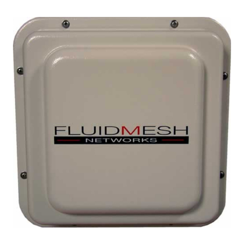
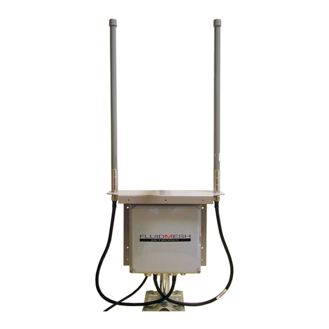
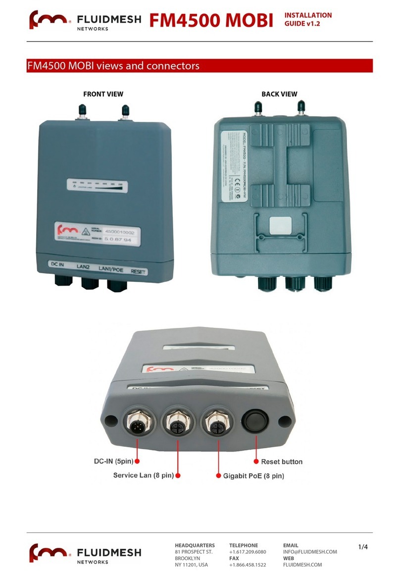
Fluidmesh Videomesh 2200 Series User manual

VideomeshTM 2200 Series
User’s manual
Firmware Version 1.4
VideomeshTM 2200 Series
Copyright 2005 Fluidmesh Networks, Inc.

WARNING
ONLY QUALIFIED PERSONNEL SHOULD INSTALL THIS UNIT AND THE
INSTALLATION SHOULD CONFORM TO ALL LOCAL CODES. IN SOME
COUNTRIES, A CERTIFIED ELECTRICIAN SHOULD INSTALL THIS UNIT.
CAUTION
When open, the apparatus should not be to dripping or splashing and no object
filled with liquid shall be placed on the apparatus.
NOTICE TO USERS
Copyright Fluidmesh Networks, Inc. All rights reserved. This manual or the
software described herein, in whole or in part, may not be reproduced, translated
or reduced to any machine-readable form without prior written approval from
Fluidmesh Networks, Inc.
FLUIDMESH NETWORKS, INC. PROVIDES NO WARRANTY WITH REGARD
TO THIS MANUAL. THE SOFTWARE OR OTHER INFORMATION
CONTAINED HEREIN AND HEREBY EXPRESSLY DISCLAIMS ANY IMPLIED
WARRANTIES OF MERCHANTABILITY OR FITNESS FOR ANY PARTICULAR
PURPOSE WITH REGARD TO THIS MANUAL, THE SOFTWARE OR SUCH
OTHER INFORMATION. IN NO EVENT SHALL FLUIDMESH NETWORKS, INC.
BE LIABLE FOR ANY INCIDENTAL, CONSEQUENTIAL OR SPECIAL
DAMAGES, WHETHER BASED ON TORT, CONTRACT, OR OTHERWISE,
ARISING OUT OF OR IN CONNECTION WITH THIS MANUAL, THE
SOFTWARE OR OTHER INFORMATION CONTAINED HEREIN OR THE USE
THEREOF.
Fluidmesh Networks, Inc. reserves the right to make any modification to this
manual or the information contained herein at any time without notice.
The software described herein may also be governed by the terms of a separate
user license agreement.
Fluidmesh, Videomesh are trademarks of Fluidmesh Networks, Inc.
Microsoft, Windows, Internet Explorer are registered trademarks of Microsoft
Corporation in the United States and/or other countries.
Ethernet is a registered trademark of Xerox Corporation.
All other brands and product names are trademarks or registered trademarks of
their respective owners.
2

TABLES OF CONTENTS
Manual Overview
Precautions
Getting Started
Introduction
Mesh Networking Basics
Addressing in a VideomeshTM Network
Software and Hardware Prerequisites
Hardware Set-up and Configuration
Proper Installation Procedures
Powering the Wireless Router
Connecting and Configuring IP cameras
Installing a Video-server in the Videomesh enclosure
Configuring a Video-server
Factory Default Hardware Reset
Graphical User Interface and Configuration
Logging into the web-based interface
Navigating the User Interface
Changing Country
General Settings: Mode and LAN
Wireless Settings
Router Statistics
Routing Table
Upgrading Videomesh Firmware
Advanced Settings
Wired LAN Configuration
Troubleshooting
I am unable to get the login screen
I am unable to login into the web-based interface
I forgot the administrator password
I am unable to get any video from the cameras
3

MANUAL OVERVIEW
This manual explains how to install and operate a VideomeshTM 2200 unit.
Note that the displays shown in this manual are explanatory examples. Some
displays may be different from the ones, which appear as you operate the
configuration software.
Depending on your system, certain displays or illustrations in this manual, when
printed out, may differ from those as portrayed on your screen.
PRECAUTIONS
This product is for professional use only.
This product has been designed with safety in mind. However, if not used
properly, electrical products can cause fires, which may lead to serious body
injuries. To avoid such accidents, make sure that you are properly qualified to
install this product and be sure to head the following.
In c se of bre kdown
In case of system breakdown, discontinue use and contact immediately your
authorized Fluidmesh Networks dealer or directly Fluidmesh Networks, Inc.
In c se of bnorm l oper tions
If the unit emits smokes or unusual smell
If water or other foreign object enter the enclosure
If your drop the unit or damage the enclosure
Disconnect the unit and contact your authorized Fluidmesh Networks dealer.
4

GETTING STARTED
This section will introduce you mesh networking architecture and the basic
operations using a Videomesh unit.
Mesh Networking B sics
Using VideomeshTM technology for your video-surveillance system allows you to
take advantage of the powerful wireless mesh networking architecture.
In a wireless mesh network, every VideomeshTM unit is connected to multiple
other units at the same time and it is able to transmit data packets using the
optimal path at any point in time. A VideomeshTM acts not only as a transmitter of
video streams coming from the cameras attached to it, but also as “intelligent”
relay, forwarding data packets coming from other VideomeshTM units.
A VideomeshTM has two modes of operations:
Camera/relay mode
Gateway mode
C mer /rel y mode: It is the default mode for every Videomesh unit. Every unit
that is not connected to the wired LAN but it only connected by radio to other
units must be set in camera/relay mode.
G tew y mode: In a mesh networks, a gateway is a unit that is connected at the
same time by radio with other units and with a cable to the wired LAN. The
gateway(s) allows interaction between the wireless mesh network and any
traditional IP-based wired network.
5

Addressing in Videomesh Wireless Network
Every VideomeshTM unit comes with a factory-set unique IP address for the
wireless interfaces in the flowing format:
5.a.b.c
The value of a, b and c are unique for every Videomesh Router manufactured
and they form the Videomesh primary serial number. This wireless IP cannot be
changed by the user and it is independent from the mode of operation: it does
not change if the unit is in camera/relay or gateway mode.
At the same time, every Videomesh has different IP addresses for the different
wired Ethernet interfaces. The way these addresses are assigned changes if the
router is in camera/relay or gateway mode.
C mer /rel y mode: In camera/relay mode, all the IP addresses are assigned
to the router. The IP address of the router cannot be changed. The IP addresses
of the cameras attached to the router can be changed in the advanced interface
settings. The default IP addresses are assigned according to the following
convention.
The first Ethernet interface gets the following network settings:
IP Address: 1.0.0.1
Netmask: 255.0.0.0
The second Ethernet interface gets the following network settings:
IP Address: 2.0.0.1
Netmask: 255.0.0.0
6

In order to work properly with a VideomeshTM unit in camera/relay mode, every IP
camera or video-server needs to be properly configured according to the
following scheme.
Any camera or video server attached to the first Ethernet interface must be
configured with the following LAN settings:
IP Address: 1.a.b.c
Netmask: 255.0.0.0
Default Gateway: 1.0.0.1
Where a, b and c are the unique values that form the primary serial number of
the VideomeshTM unit that the camera is attached to.
Any camera or video server attached to the second Ethernet interface must be
configured with the following LAN settings:
IP Address: 2.a.b.c
Netmask: 255.0.0.0
Default Gateway: 2.0.0.1
Where a, b and c are the unique values that form the primary serial number of
the VideomeshTM unit that the camera is attached to.
Softw re nd H rdw re Requirements
Every VideomeshTM unit can be configured through a web-based interface. To
perform the web-based configuration you need a PC with a web-browser, an
Ethernet LAN interface and a crossover Ethernet cable.
Suggested hardware
Cat5 Crossover Ethernet cable with RJ45 connectors
PC computer with the following characteristics:
−Windows XP or Windows 2000. In this manual, we are assuming
you are using Windows XP and every instruction or screenshot is
based on this assumption. Likely, a VideomeshTM can be
configured also using other OS, such as Linux or older version of
Windows. However, we have not tested these other OS with a
VideomeshTM.
−Microsoft Internet Explorer 6. Likely, a VideomeshTM can be
configured also using other browsers such as older versions of
Internet Explorer, Firefox or Safari but these browsers have not
been tested. In this manual, we assume that you are using
Microsoft Internet Explorer.
−Wired Ethernet Network C rd.
7

−Hardware requirements in terms of CPU, RAM, hard drive allowing
proper operations of Windows XP and Microsoft Internet Explorer
6.
8

VideomeshTM H rdw re Set-up
A VideomeshTM 2200 is a product designed for outdoor operations in harsh
environments. The waterproof enclosure contains a 35W transformer that is
used to power the VideomeshTM internal board and any other equipment that
needs to be installed inside the enclosure, such as one or more video-servers.
Proper Inst ll tion Procedures
The unit can be installed on a wall or it can be pole-mounted. Brackets to install
the unit on a wall are sold with the unit. Other types of mounting kits, such as
pole-mounting kits, can be bought separately from Fluidmesh Networks’ dealers.
Make sure to buy the proper mounting kit to safely install every VideomeshTM
unit.
In order to prevent excessive heating of the unit beyond the operational
temperature, Fluidmesh Networks manufactures and sells through its dealers a
Videomesh SunShield. In case any Videomesh unit must stay under direct solar
radiation for long periods of time, you are strongly encouraged to buy and install
a Videomesh SunShield for the unit to avoid overheating.
Powering the VideomeshTM
The unit comes with an internal 35W AC-to-DC transformer. The transformer is
used to power the VideomeshTM internal board and it can be used to power other
electrical equipment that needs to be installed inside the enclosure, such as a
video-servers. You are provided with a copy of the transformer specifications
within the VideomeshTM documentation. In case you want to use the transformer
9
35W AC-DC
tr nsformer
AC 100-240V
50/60Hz
power input
W ter-tight
gl nds for
Ethernet nd
co x c bles
Reset f ctory-
def ult
settings (keep
it pressed for
more th n 15
seconds)
12 V DC
outputs for up
to two video-
servers
Auxili ry AC
Power Output
Ethernet
Interf ce 0
Ethernet
Interf ce 1

to power other equipment such as a video server, make sure to understand the
technical details and to be qualified to perform the work. The VideomeshTM has a
power consumption up to 10W. Any electrical equipment that you attach to the
internal transformer needs to draw less than 25W (aggregate in case you install
more than one piece of equipment).
In order to guarantee that no water enter the enclosure, make sure that the
power cable that you are using though the watertight glands has a proper
diameter. The enclosure is equipped with two types of watertight glands that
guarantee water tightness. Data cables (Ethernet or coaxial cables) diameters
must be between 0.16 and 0.31 inches (4.1-7.9 mm) and the AC power cable
must be between 0.16 and 0.31 inches (4.1-7.9 mm).
Connecting nd Configuring IP c mer s
The unit has two Ethernet ports that can be used to connect directly up to 2 IP
cameras. Connect the cameras using an Ethernet crossover cable. Make sure to
use a cable manufactured for outdoor usage.
Make sure that every Videomesh with cameras directly attached are configured
in camera/relay mode.
In order to work properly within a Videomesh network, the IP cameras attached
to the Ethernet interfaces need to be configured with the following network
settings.
Camera attached to the first Ethernet interface:
IP Address: 1.a.b.c
Netmask: 255.0.0.0
Default Gateway: 1.0.0.1
Camera attached to the second Ethernet interface:
IP Address: 2.a.b.c
Netmask: 255.0.0.0
Default Gateway: 2.0.0.1
Where a, b and c are the unique values that form the primary serial number of
the Videomesh where the camera is attached.
Multicast Streaming
In case you want to use the IP cameras in multicast mode, you must configure
the multicast settings of the camera in the following way.
IP camera attached to the first Ethernet Interface:
Multicast Group: 224.a.b.c
10

TTL: Greater than 2
IP camera attached to the second Ethernet interface:
Multicast Group: 225.a.b.c
TTL: Greater than 2
Where a, b and c are the unique values that form the primary serial number of
the Videomesh where the camera is attached.
Inst lling Video-server in the VideomeshTM enclosure
One or more video-server can be directly installed in the Videomesh enclosure.
In order to install a video server in the enclosure you need to buy a Fluidmesh
Video-Server Kit from your Fluidmesh Networks dealer. The kit contains a
movable plate that can be installed in the enclosure. The movable plate can be
placed at different heights based on the dimension of the video server. You can
install and screw the video-server(s) on the moveable plate.
The transformer installed in the Videomesh is able to power one or more video
servers beyond the router board itself. The transformer installed provides 12 V
DC. Make sure that all the video servers you are using drain less that 20 W of
aggregate power under every possible condition.
The transformer detailed specifications are provided with the Videomesh
documentation. Before powering a video server with the provided transformer,
make sure to understand all the technical details involved and to be qualified to
perform the work.
Configuring Video-server
Make sure that every Videomesh with video-server directly attached are
configured in camera/relay mode.
In order to work properly within a Videomesh network, the video-servers attached
to the Ethernet interfaces must be set with the following network settings.
Video-server attached to the first Ethernet interface:
IP Address: 1.a.b.c
Netmask: 255.0.0.0
Default Gateway: 1.0.0.1
Video-server attached to the second Ethernet interface:
IP Address: 2.a.b.c
Netmask: 255.0.0.0
Default Gateway: 2.0.0.1
11

Where a, b and c are the unique values that form the primary serial number of
the Videomesh where the camera is attached.
Multicast Streaming
In case you want to use the IP cameras in multicast mode, you must configure
the multicast settings of the camera in the following way.
Video-server attached to the first Ethernet Interface:
Multicast Group: 224.a.b.c
TTL: Greater than 2
Video-server attached to the second Ethernet interface:
Multicast Group: 225.a.b.c
TTL: Greater than 2
Where a, b and c are the unique values that form the primary serial number of
the Videomesh where the camera is attached.
F ctory Def ult H rdw re Reset
The red button present inside the Videomesh enclosure allows resetting the
Videomesh to the factory default settings.
In case you want to reset the factory default settings, power the Videomesh and
keep the red button pressed for at least 30 seconds. The Videomesh will reset its
factory default settings and it will automatically reboot.
After resetting the factory default settings, the Videomesh will be back in
camera/relay mode and the administrator’s password will be reverted to:
Username: admin
Password: admin
Connecting the Antenn s
The Videomesh 2200 Series has two N-Female Bulkhead connectors for
antennas. Looking at the Videomesh 2200 from the front, the right-hand
connector is for the 5 GHz antenna and the left-hand connector is for the 2.4
GHz antenna.
The antennas need to be connected using an appropriate low-loss coaxial cable
with N-Male connector.
For outdoor usage, using a lighting protector is strongly encouraged. Make sure
to use a low-loss lighting protector with appropriate frequency range.
12

Your Fluidmesh Networks’ dealer can provide you appropriate lighting protectors,
pre-assembled low-loss coaxial cables and high-gain antennas.
13

Web-b sed Interf ce nd Configur tion
The Videomesh can be configured using a web-based graphical user interface
(GUI).
Initially every Videomesh is configured in camera/relay mode and it can be
configured attaching a computer to the VideomeshTM using an Ethernet
crossover cable.
Logging into the web-b sed interf ce
Attach an Ethernet crossover cable with RJ45 connectors between a computer
and the Videomesh that you want to configure using the first Ethernet port of the
Videomesh. If your computer is configured to receive the IP address from a
DHCP server, it should receive immediately an IP address.
In case your computer is not configured to receive an IP address automatically,
go to the troubleshooting section where you can learn how to perform a manual
IP configuration of your computer.
Disable the Access the Internet using proxy server function. To disable this
function, go to Control P nel > Internet Options > Connections > LAN
Settings and uncheck the enable box.
Open a web-browser such as Internet Explorer and type the following URL:
http //1.0.0.1
Make sure you do not omit the initial “http://”. Some browsers might not work is
you do not write “http://” in front of numeric addresses.
At this point you should get a login-form asking a user name and a password.
The default settings are the following:
Username: admin
Password: admin
14

To preserve the security of your system, make sure to change the default
password as soon as possible.
In case you are not getting the logging screen, look in the troubleshooting
section.
End-user license greement nd region of oper tion
After the login, the web-based user interface allows you to change the settings of
the Videomesh. The first time you log-in, you will be asked to accept the terms of
the end-user license agreement and to select the region where you plan to
operate the unit. You must accept the term of the license agreement in order to
activate the device. If you do not wish to accept the term of the license
agreement, please turn off the unit and return it to your Fluidmesh dealer.
Picking the wrong country/regulatory domain setting might make the Videomesh
operations illegal in your country.
15

N vig ting the web-b sed interf ce
The menu on the right allows you to navigate through the settings of the
Videomesh.
The first setting you should change is the country where you want to operate the
Videomesh. Different countries have different telecommunications regulations
and the country setting allows you to operate the Videomesh complying with
different national regulations.
The available frequencies and other settings related to the radios operation will
vary based on the selected country.
Picking the wrong country might make the Videomesh operations illegal in your
country.
In order to change the country, select “Wireless settings”
Gener l Settings: Mode nd LAN
Every Videomesh has two modes of operations:
C mer /rel y mode
G tew y mode
The factory default mode is the camera/relay mode.
To change the mode, click on the “General Settings” link on the right-hand menu.
The page will appear changes based on the selected mode.
In case you are currently in camera mode, the following page will appear:
16

No other option is given in terms of LAN settings if the router is in camera mode.
The settings of the two Ethernet interfaces are pre-determined and cannot be
changed by the user.
If you select gateway mode you will also need to input the LAN settings of the
wired network where you want to attach the router.
In the majority of cases, the DHCP client should be disabled.
In case you do not know the LAN setting you should use, contact the local
network administrator before changing the settings of the gateway.
Wireless Settings
The wireless settings concern the wireless network operation.
17

The shared passphrase is a secret that must be shared only among the
Videomesh forming a single network. Every Videomesh that does not have the
right passphrase will not be able to communicate with the routers of your
network. Different passphrase can also be used to create separate wireless
networks in same area and sharing the same frequencies.
The second setting is the country where you want to operate the Videomesh.
Different countries have different telecommunications regulations and the
country setting allows you to operate the Videomesh complying with different
national regulations.
The available frequencies and other settings related to the radios operation will
vary based on the selected country.
Picking the wrong country/regulatory domain setting might make the Videomesh
operations illegal in your country.
Pick the country where you want to operate the Videomesh and save the settings
before deciding which frequencies to use.
The last setting you can change regards the frequency band used by the two
radios. Every Videomesh 2200 Series is equipped with two radios, one operating
in the 2.4 GHz range and one operating in the 5 GHz range. Every radio
operates using a 20 MHz band. You change the frequency band in order to
minimize the interference with other wireless networks operating in the same
area.
The frequencies you can select are the carrier frequencies. Not all of them are
non-interfering because the frequency band used is 20 MHz wide and centered
at the carrier frequency.
Router St tistics
The Videomesh Statistics page allows you to check important statistics related to
the Videomesh.
18

Uptime. Time counter from last reboot.
MAC Address. The MAC address of the first Ethernet Interface. It might be
needed to properly configure the LAN attached to the gateway.
V lid Routes. The number of possible paths to reach the wired LAN through a
gateway.
Aver ge Medi n Hops. The number of transmission that the router performs to
reach the wired LAN. On average One hop means that the router is able to reach
the gateway without routing through any other router as relay. Two hops mean
that between this router and a gateway there is one other router that acts as a
relay.
Hops R nge. The maximum and minimum number of hops to reach the gateway
that has been experience by the router.
Routing T ble
Using this page, you can check the routing table currently in use by the
Videomesh.
19

The routing table shows the path that is currently used to reach every possible
destination unit.
The “Hops” value shows the number of routers that the packets go though before
reaching the destination unit. One hop meas that there is a direct connection
between the two Videomesh. Two hops means that there is one Videomesh unit
that acts as a relay in the middle.
The “destination IPs” marked with an asterisk (*) are Videomesh units in gateway
mode.
This page is particularly useful for network planning and troubleshooting.
Upgr de Videomesh Firmw re
Using this page you can upgrade the Videomesh Firmware to the most current
version available.
Download on you PC the firmware upgrade file from the Fluidmesh Networks
website. Select the file on your hard disk and upload it on the Videomesh unit.
This operation might take several minutes. The unit will automatically reboot at
the end of the upgrade process.
20
Table of contents
Other Fluidmesh Wireless Access Point manuals
Popular Wireless Access Point manuals by other brands
Ubiquiti
Ubiquiti PowerBeam AC GENZ quick start guide
Ruckus Wireless
Ruckus Wireless R730 Quick setup guide

TRENDnet
TRENDnet TEW-653AP Quick installation guide
Symbol
Symbol Spectrum24 AP-4100 Series Product reference guide
Atlantis Land
Atlantis Land A02-AP1-W54 manual
Extreme Networks
Extreme Networks WS-AP3801i quick reference
Lucent Technologies
Lucent Technologies WaveACCESS NET MDR232 installation guide
TP-Link
TP-Link TL-WA701ND user guide

EnGenius
EnGenius EWS330AP user manual
PROception
PROception PROAPW300L quick start guide
DragonWave
DragonWave Horizon Quantum Quick reference guide
ADS-tec
ADS-tec RAC2000 series quick start guide
