Fluidwell F197-A User manual

F197-A
SETPOINT GENERATOR
Signal input type A: (0)4-20mA
Signal outputs: (0)4-20mA or 0-10V control output and two alarm
outputs
Options: Intrinsically Safe, Modbus communication
F-Series - Field mounted indicators for safe and hazardous areas. More info: www.fluidwell.com/fseries

HF197AEN_v0501_04
Page 2
SAFETY INSTRUCTIONS
Any responsibility is lapsed if the instructions and procedures as described in this
manual are not followed.
LIFE SUPPORT APPLICATIONS: The F197-A is not designed for use in life support
appliances, devices, or systems where malfunction of the product can reasonably be
expected to result in a personal injury. Customers using or selling these products for use
in such applications do so at their own risk and agree to fully indemnify the manufacturer
and supplier for any damages resulting from such improper use or sale.
Electro static discharge does inflict irreparable damage to electronics! Before installing
or opening the unit, the installer has to discharge himself by touching a well-grounded
object.
This unit must be installed in accordance with the EMC guidelines (Electro Magnetic
Compatibility).
Do connect a proper grounding to the aluminum casing as indicated if the F197-A has
been supplied with the 115-230V AC power-supply type PM. The green / yellow wire
between the back-casing and removable terminal-block may never be removed.
Intrinsically Safe applications: follow the instructions as mentioned in Chapter 5 and
consult “Fluidwell F1..-..-XI - Documentation for Intrinsic Safety”.
DISPOSAL
At the end of its life this product should be disposed of according to local regulations regarding
waste electronic equipment. If a battery is present in this product it should be disposed of
separately. The separate collection and recycling of your waste equipment will help to conserve
natural resources and ensure that it is recycled in a manner that protects the environment.
SAFETY RULES AND PRECAUTIONARY MEASURES
The manufacturer accepts no responsibility whatsoever if the following safety rules and
precautions instructions and the procedures as described in this manual are not followed.
Modifications of the F197-A implemented without preceding written consent from the
manufacturer, will result in the immediate termination of product liability and warranty period.
Installation, use, maintenance and servicing of this equipment must be carried out by authorized
technicians.
Check the mains voltage and information on the manufacturer's plate before installing the unit.
Check all connections, settings and technical specifications of the various peripheral devices
with the F197-A supplied.
Open the casing only if all leads are free of potential.
Never touch the electronic components (ESD sensitivity).
Never expose the system to heavier conditions than allowed according to the casing
classification (see manufacture's plate and chapter 4.2.).
If the operator detects errors or dangers, or disagrees with the safety precautions taken, then
inform the owner or principal responsible.
The local labor and safety laws and regulations must be adhered to.
HF197AEN_v0501_04
Page 3
ABOUT THE OPERATION MANUAL
This operation manual is divided into two main sections:
The daily use of the unit is described in chapter 2 "Operation". These instructions are meant for
users.
The following chapters and appendices are exclusively meant for electricians/technicians. These
provide a detailed description of all software settings and hardware installation guidance.
This operation manual describes the standard unit as well as most of the options available. For
additional information, please contact your supplier.
A hazardous situation may occur if the F197-A is not used for the purpose it was designed for
or is used incorrectly. Please carefully note the information in this operating manual
indicated by the pictograms:
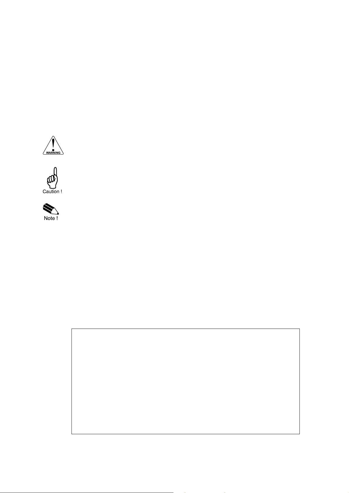
A "warning" indicates actions or procedures which, if not performed correctly, may lead to
personal injury, a safety hazard or damage of the F197-A or connected instruments.
A "caution" indicates actions or procedures which, if not performed correctly, may lead to
personal injury or incorrect functioning of the F197-A or connected instruments.
A "note" indicates actions or procedures which, if not performed correctly, may indirectly
affect operation or may lead to an instrument response which is not planned.
Hardware version : 02.01.xx
Software version : 02.05.xx
Manual : HF197AEN_v050_04
© Copyright 2011 : Fluidwell bv - The Netherlands.
Information in this manual is subject to change without prior notice. The
manufacturer is not responsible for mistakes in this material or for incidental
damage caused as a direct or indirect result of the delivery, performance or
use of this material.
© All rights reserved. No parts of this publication may be reproduced or used
in any form or by any means without written permission of your supplier.

HF197AEN_v0501_04
Page 4
CONTENTS MANUAL
Safety instructions ........................................................................................................................................... 2
Disposal .................................................................................................................................................... 2
Safety rules and precautionary measures ....................................................................................................... 2
About the operation manual ............................................................................................................................ 3
Contents manual.............................................................................................................................................. 4
1. Introduction ................................................................................................................................. 5
1.1. System description of the F197-A.......................................................................................... 5
2. Operational.................................................................................................................................. 7
2.1. General .................................................................................................................................. 7
2.2. Control panel.......................................................................................................................... 7
2.3. Operator information and functions ....................................................................................... 8
3. Configuration............................................................................................................................. 10
3.1. Introduction .......................................................................................................................... 10
3.2. Programming SETUP-level.................................................................................................. 10
3.2.1. General ................................................................................................................................ 10
3.2.2. Overview functions SETUP level ......................................................................................... 13
3.2.3. Explanation OF SETUP-functions........................................................................................ 14
1 - Sensor ....................................................................................................................... 14
2 - Output ........................................................................................................................ 15
3 - Alarm ......................................................................................................................... 15
4 - Power management .................................................................................................. 16
5 - Sensor ....................................................................................................................... 16
6 - Analog output............................................................................................................. 18
7 - Communication (optional).......................................................................................... 19
8 - Others ........................................................................................................................ 19
4. Installation ................................................................................................................................. 20
4.1. General directions................................................................................................................ 20
4.2. Installation / surrounding conditions .................................................................................... 20
4.3. Dimensions- Enclosure ........................................................................................................ 21
4.4. Installing the hardware......................................................................................................... 23
4.4.1. Introduction .......................................................................................................................... 23
4.4.2. Voltage selection sensor supply .......................................................................................... 24
4.4.3. Terminal connectors ............................................................................................................ 25
5. Intrinsically safe applications..................................................................................................... 31
5.1. General information and instructions ................................................................................... 31
5.2. Terminal connectors Intrinsically Safe applications ............................................................. 32
5.3. Configuration examples Intrinsically Safe applications........................................................ 34
5.4 Battery replacement instructions.......................................................................................... 36
6. Maintenance.............................................................................................................................. 37
6.1. General directions................................................................................................................ 37
Appendix A: Technical specification .............................................................................................................. 38
Appendix B: Problem solving......................................................................................................................... 41
Appendix C: Communication variables.......................................................................................................... 42
Index of this manual....................................................................................................................................... 43
List of figures in this manual .......................................................................................................................... 43

HF197AEN_v0501_04
Page 5
1. INTRODUCTION
1.1. SYSTEM DESCRIPTION OF THE F197-A
Functions and features
The setpoint generator model F197-A is a microprocessor driven instrument designed for manually
control of a device with a (0)4-20mA or 0-10V signal. Moreover, an input value can be displayed but
has no control link with the output value.
This product has been designed with a focus on:
ultra-low power consumption to allow long-life battery powered applications (type PB / PC),
intrinsic safety for use in hazardous applications (type XI),
several mounting possibilities with ABS or aluminum enclosures for harsh industrial
surroundings,
ability to process all types of sensor signals,
transmitting possibilities with two alarm and communication (option) outputs.
Sensor input
This manual describes the unit with a (0)4-20mA sensor input "-A version". Other versions are
available to process pulse or 0-10V signals.
One sensor with a (0)4-20mA output can be connected to the F197-A. To power the sensor, several
options are available.
Standard outputs
Linear (0)4-20mA or 0-10V control output with 10-bits resolution to control a device manually.
The setpoint as well as the minimum and maximum signal output can be tuned.
Two transistor or relay (option) outputs for high / low alarm, relatedto the input value.
Fig. 1: Typical application for the F197-A.
Overview typical application F197
RS232/RS485
Modbus (option)
manual
(0)4-20mA / 0-10V
output
hot
cold
high
alarm output
low
alarm output

HF197AEN_v0501_04
Page 6
Configuration of the unit
The F197-A was designed to be implemented in many types of applications. For that reason, a
SETUP-level is available to configure your F197-A according to your specific requirements.
SETUP includes several important features, such as Span, measurement units, signal selection etc.
All setting are stored in EEPROM memory and will not be lost in the event of power failure or a
drained battery.
To extend the battery-life time (option), please make use of the power-management functions as
described in chapter 3.2.3.
Display information
The unit has a large transflective LCD with all kinds of symbols and digits to display measuring units,
status information, trend-indication and key-word messages.
Options
The following options are available: isolated or active 4-20mA / 0-10V / 0-20mA analog output, full
Modbus communication RS232/485 (also battery powered), intrinsic safety, mechanical relay or
active outputs, power- and sensor-supply options, panel-mount, wall-mount and weather-proof
enclosures, flame proof enclosure.

HF197AEN_v0501_04
Page 7
2. OPERATIONAL
2.1. GENERAL
The F197-A may only be operated by personnel who are authorized and trained by the
operator of the facility. All instructions in this manual are to be observed.
Take careful notice of the " Safety rules, instructions and precautionary measures " in
the front of this manual.
This chapter describes the daily use of the F197-A. This instruction is meant for users / operators.
2.2. CONTROL PANEL
The following keys are available:
Fig. 2: Control Panel.
Functions of the keys
This key is used to program and save new values or settings.
It is also used to gain access to SETUP-level; please read chapter 3.
This key is used to SELECT the alarm values.
The arrow-key is used to increase a value after PROG has been pressed
or to configure the unit; please read chapter 3.
The arrow-key is used to select a digit after PROG has been pressed or to
decrease a value or to configure the unit; please read chapter 3.

HF197AEN_v0501_04
Page 8
2.3. OPERATOR INFORMATION AND FUNCTIONS
In general, the F197-A will always function at Operator level. The information displayed is dependant
upon the SETUP-settings. If available, a sensor can be connected to the F197 to display the actual
value. However, there is NO control relationship between the output value and the sensor input
value. The signal generated by the connected sensor is measured by the F197-A in the background,
whichever screen refresh rate setting is chosen. After pressing a key, the display will be updated
very quickly during a 30 second period, after which it will slow-down again.
To enter a setpoint / preset value
Related to the configuration of the F197, a setpoint value can be entered as a value or by
using the center button to increase a value and the left button to decrease the value.
The value to be entered is an absolute or mA value or a percentage.
To enter the value, following procedure must be followed:
1) press PROG: the word "PROGRAM" will be flashing,
2) use to select the digits and to increase that value. A negative value (e.g.
-40°F) can be entered by pressing the middle and right button simultaneously.
3) set the new PRESET-value by pressing ENTER.
Fig. 3: Example display information during entering preset value.
When data is altered but ENTER has not been pressed yet, then the alteration can still be
cancelled by waiting for 20 seconds or by pressing ENTER during three seconds: the former
value will be reinstated.
Please note: alterations will only be set after ENTER has been pressed!
To increase / decrease the value, following procedure must be followed:
1) press PROG: the word "PROGRAM" will be flashing,
2) use to increase the value and to decrease the value. The longer the key is
pressed, the faster it will increase or decrease.
3) set the new PRESET-value by pressing ENTER.
Please note: related to the configuration of the F197, it might be that the new value
is active inmediately or first after pressing ENTER.
The new value must however ALWAYS be confirmed by pressing ENTER, else the
former value will be re-installed.
Fig. 4: Example display information during increasing / decreasing preset value.
PROGRAM
PROGRAM

HF197AEN_v0501_04
Page 9
Programming the alarm values
Note: This function might not be available or accessible due to a configuration setting.
When the SELECT-key is pressed a few times, the values are displayed. These values are related
to the input value of the sensor:
1) low alarm: enter here 830 °C for example.
2) high alarm: enter here 1200 °C for example.
To change the alarm value, the following procedure must be executed:
1) press PROG: the word "PROGRAM" will flash or a pass code will be requested,
2) use to select the digits and to increase that value,
3) confirm the new alarm value by pressing ENTER.
Fig. 4: Example of display information during programming low alarm value.
When data is altered but ENTER has not been pressed yet, then the alteration can still be
cancelled by waiting for 20 seconds or by pressing ENTER during three seconds: the former
value will be reinstated.
High or low alarm
When the actual sensor value is outside the allowed range, an alarm message will be
displayed indicating the type of alarm: "LO ALARM" or "HI ALARM". An alarm might first be
initiated after a certain period of time due to configuration settings.
The alarm is terminated automatically as soon as the value is within its range again.
Low-battery alarm
When the battery voltage drops, it must be replaced. At first "low-battery" will flash, but as
soon as it is displayed continuously, the battery MUST be replaced shortly after!
Only official batteries may be used, or else the guarantee will be terminated. The remaining
lifetime after the first moment of indication is generally several days up to some weeks.
Fig. 5: Example of low-battery alarm.
Alarm 01-03
When "alarm" is displayed, please consult Appendix B: problem solving.
HF197AEN_v0501_04
Page 10
3. CONFIGURATION
3.1. INTRODUCTION
This and the following chapters are exclusively meant for electricians and non-operators. In these,
an extensive description of all software settings and hardware connections are provided.
Mounting, electrical installation, start-up and maintenance of the instrument may only
be carried out by trained personnel authorized by the operator of the facility. Personnel
must read and understand this Operating Manual before carrying out its instructions.
The F197-A may only be operated by personnel who are authorized and trained by the
operator of the facility. All instructions in this manual are to be observed.
Ensure that the measuring system is correctly wired up according to the wiring
diagrams. The housing may only be opened by trained personnel.
Take careful notice of the " Safety rules, instructions and precautionary measures " in
the front of this manual.
3.2. PROGRAMMING SETUP-LEVEL
3.2.1. GENERAL
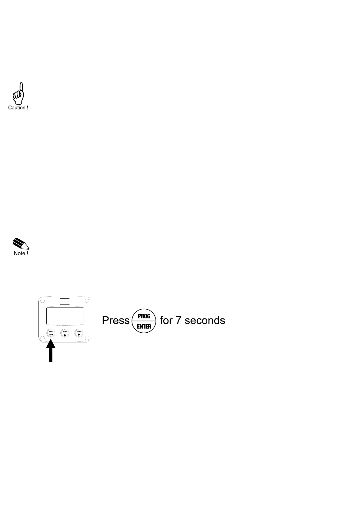
Configuration of the F197-A is done at SETUP-level. SETUP-level is reached by pressing the
PROG/ENTER key for 7 seconds; at which time, both arrows will be displayed. In order to return
to the operator level, PROG will have to be pressed for three seconds. Alternatively, if no keys are
pressed for 2 minutes, the unit will exit SETUP automatically.
SETUP can be reached at all times while the F197-A remains fully operational.
Note: A pass code may be required to enter SETUP. Without this pass code access to SETUP is
denied.
To enter SETUP-level:

HF197AEN_v0501_04
Page 11
Matrix structure SETUP-level:
SCROLLING THROUGH SETUP-LEVEL
Selection of function-group and function:
SETUP is divided into several function groups and functions.
Each function has a unique number, which is displayed below the word "SETUP" at the bottom of
the display. The number is a combination of two figures. The first figure indicates the function-group
and the second figure the sub-function. Additionally, each function is expressed with a keyword.
After selecting a sub-function, the next main function is selected by scrolling through all "active" sub-
functions (e.g. 1, 11, 12, 13, 14, 1, 2, 3, 31 etc.).

HF197AEN_v0501_04
Page 12
To change or select a value:
To change a value, use to select the digits and to increase that value.
To select a setting, both and can be used.
If the new value is invalid, the increase signor decrease-signwill be displayed while you are
programming.
When data is altered but ENTER is not pressed, then the alteration can still be cancelled by waiting
for 20 seconds or by pressing ENTER for three seconds: the PROG-procedure will be left
automatically and the former value reinstated.
Note: alterations will only be set after ENTER has been pressed!
To return to OPERATOR-level:
In order to return to the operator level, PROG will have to be pressed for three seconds. Also, when
no keys are pressed for 2 minutes, SETUP will be left automatically.

HF197AEN_v0501_04
Page 13
3.2.2. OVERVIEW FUNCTIONS SETUP LEVEL
SETUP FUNCTIONS AND VARIABLES
1 INPUT
11 SENSOR VALUE disable - enable
12 UNIT no unit - mm - cm - m - meter - mil - in - ft - yd - fath - sqft
- ml - l -nl - al - m3 - nm3 - am3 - gal - usgal - igal - bbl -
cuft - mg - g - kg - ton - oz - lb - st - qr - cwt - psi - psig -
mbar - mbarg - bar - barg - pa - pag - kpa - kpag - mmh2o
- mh2o - inh20 - mmhg - inhg - °C - °F - K - p - rpm - % -
ppm.
13 TIME UNIT sec - min - hour - day - off
14 DECIMALS 0 - 1 - 2 - 3 (Ref: displayed value)
15 SPAN 0.000001 - 9,999,999 unit
16 DECIMALS SPAN 0 - 6
17 OFFSET -999,999 - +999,999 units
2 OUTPUT
21 PRESET SET enter - setup - scroll - edit
22 UNIT input - mA - %
25 PRESET -999,999 - +999,999 units
3 ALARM
31 ALARM SET operate - setup - disable
32 OFFSET ignore - default - no relay
33 ALARM LO -999,999 - +999,999 units
34 ALARM HI -999,999 - +999,999 units
35 DELAY ALARM LO 0.1 - 999.9 seconds
36 DELAY ALARM HI 0.1 - 999.9 seconds
4 POWERMANAGEMENT
41 LCD UPDATE fast - 1 sec - 3 sec - 15 sec - 30 sec - off
42 BATTERY MODE operational - shelf
5 SENSOR
51 FORMULA interpolation, square root
52 FILTER 00 - 99
53 CUT-OFF 0.0 - 99.9%
54 CALIBRATE LOW (0)4mA
55 CALIBRATE HIGH 20mA
6 ANALOG
61 OUTPUT disable - enable
62 OUTPUT MINIMUM -999,999 - +999,999 units
63 OUTPUT MAXIMUM -999,999 - +999,999 units
64 CUT-OFF 0.0 - 9.9%
65 TUNE MIN - (0)4mA / 0V 0 - 9,999
66 TUNE MAX- 20mA / 10V 0 - 9,999
67 FILTER 00 - 99
7 COMMUNICATION
71 SPEED / BAUDRATE 1200 - 2400 - 4800 - 9600
72 ADDRESS 1 - 255
73 MODE rtu - off
8 OTHERS
81 TYPE / MODEL F197–A / F197–U
82 SOFTWARE VERSION xx.xx.xx
83 SERIAL NO. xxxxxxx
84 PASSWORD 0000 - 9999
85 TAGNUMBER 0000000 - 9999999

HF197AEN_v0501_04
Page 14
3.2.3. EXPLANATION OF SETUP-FUNCTIONS
1 - SENSOR
The settings for sensor do not influence the output signal directly. The input signal is just used to
display and monitor a value at the operator level, which is likely influence by the setpoint generator.
The display update time for this value is one second or more.
Note: some of these settings also influence other settings.
SENSOR VALUE
11
If a sensor is available to display the actual value, do select enable to
make this function available for the operator. Else select disable.
MEASUREMENT UNIT
12
SETUP - 12 determines the measurement unit:
The following units can be selected:
no unit - mm - cm - m - meter - mil - in - ft - yd - fath - sqft - ml - l -
nl - al - m3 - nm3 - am3 - gal - usgal - igal - bbl - cuft - mg - g - kg
- ton - oz - lb - st - qr - cwt - psi - psig - mbar - mbarg - bar - barg -
pa - pag - kpa - kpag - mmh2o - mh2o - inh20 - mmhg - inhg - °C -
°F - K - p - rpm - % - ppm.
Alteration of the measurement unit will have consequences for operator
and SETUP-level values.
Please note that the Span has to be adapted as well; the calculation is not
done automatically.
TIME UNIT
13
The unit can be displayed as a rate, e.g. L/min. The rate can be displayed
per second (SEC), minute (MIN), hour (HR) or day (DAY).
DECIMALS
14
This setting determines for the number of digits following the decimal
point. The following can be selected:
00000 - 1111.1 - 222.22 - 333.333
SPAN
15
With the span, the sensor signal is converted to the selected units (setup
12 and 13).
The span is determined on the basis of the selected measurement unit
and time unit at 20mA.
Enter the span in whole numbers (decimals are set with SETUP 16).
The more accurate the span, the more accurate the functioning of the
system will be.
Example 1 Calculating the span for flowrate
Let us assume that the sensor generates 20mA at a
flowrate of 2,481.3 Liters/minute, the selected unit is
"Liters" and time unit "minute".
The span is 2481.3 Enter for SETUP15: "248130" and for
SETUP16 - decimals span "2".
Example 2 Calculating the span for level
Let us assume that the sensor generates 20mA at a level
of 652.31 USGAL, the selected unit is USG and the offset
value is 200 (setup 17).
The span is 652.31-200=452.31. Enter for SETUP 14:
"452.31 and for SETUP 15 "2" and SETUP 16 “200”.
DECIMALS SPAN
16
This setting determines the number of decimals for Span
(SETUP 15). The following can be selected:
0 - 1 - 2 - 3 - 4 - 5 - 6
Please note that this SETUP - influences the accuracy of the Span
indirectly.
This setting has NO influence on the displayed number of digits for
(SETUP 14)!
OFF SET
17
Enter here the "not measured" value which is below the sensor, in case a
pressure transducer e.g. is used to measure the level.
Also, a negative offset can be entered: do press the middle and left button
simultaneously - e.g. for -85°F.
HF197AEN_v0501_04
Page 15
2 - OUTPUT
PRESET SET
21
With this function it is determined how the opertor has to enter a new
setpoint value. The following can be selected:
enter: the digits have to be selected and each digit is increased
individually.
setup: as enter, but the value can NOT be chganged by the operator,
only at setup level (setup 23)
scroll: the value will increase by pressing the center button or decrease
by pressing the left button. The value is inmediatly valid.
edit: as scroll, but the value is first valid after pressing ENTER.
UNIT
22
This function determines the measurement unit for the setpoint.
The following units can be selected:
unit: the measuring unit as selected with setup 12 will be displayed.
Consequently, the setpoint range will be 6 digits (incl. max three decimals
- setup 14)
mA: the setpoint value will be mA.
Consequently, the setpoint range will be 4 digits (incl. one decimal)..
%: the setpoint value will be %.
Consequently, the setpoint range will be 4 digits (incl. one decimal).
PRESET
23
With this setting a setpoint (preset value) can be entered. As this value is
at opertor level, it can be password protected (setup 84 and 21).
3 - ALARM
If setup 11 is enabled, the sensor value can be monitored with these alarm settings.
Consequently, the low and high alarm outputs will be switched in case of an alarm.
Please be aware that the alarm levels can be programmed at operator level as well. Moreover, the
function be locked out (setup 31).
ALARM SET
31
This function determines following:
operate: the alarm values can be set at both Operator level and SETUP-
level.
setup: the alarm values can be set at SETUP-level only, but are still
visible for the operetor
disable: the monitoring function is switched-off and not visible for the
operator.
OFFSET
32
When the signal is the minimum value, then it is possible to ignore or
disable the monitoring function. The following settings can be selected:
default: in case of a low-alarm and minimum signal value, it will switch
the alarm output and indicate the alarm on the display.
no relay: in case of a low-alarm and minimum signal value, it won't switch
the alarm output but will indicate the alarm on the display only.
ignore: in case of a low-alarm and minimum signal value, it won't switch
the alarm output and nothing will be indicated on the display.
ALARM VALUE
LOW
33
The low alarm is set with this setting. An alarm will be generated as long
as the value is lower as this value.
A negative offset can be entered: do press the middle and left button
simultaneously.
ALARM VALUE
HIGH
34
The high alarm is set with this setting. An alarm will be generated as long
as the value is higher as this value.
DELAY TIME ALARM
LOW
35
An alarm generated by SETUP 33 “low” can be ignored during X-time
period. If the actual value is still incorrect after this delay time, then an
alarm will be generated.
DELAY TIME ALARM
HIGH
36
An alarm generated by SETUP 34 “high” can be ignored during X-time
period. If the actual value is still incorrect after this delay time, then an
alarm will be generated.

HF197AEN_v0501_04
Page 16
4 - POWER MANAGEMENT
When used with the internal battery (type PB / PC), the user can expect reliable measurement over
a long period of time. The F197-A has several smart power management functions to extend the
battery life time significantly. Two of these functions can be set:
LCD NEW
41
The calculation of the display-information influences the power
consumption significantly. When the application does not require a fast
display update, it is strongly advised to select a slow refresh rate.
Please understand that NO information will be lost; the input signal will be
processed and the output signals will be generated in the normal way.
The following can be selected:
Fast - 1 sec - 3 sec - 15 sec - 30 sec - off.
Example 3: Battery life-time
battery life-time with a FAST update: about 3 years.
battery life-time with a 1 sec update: about 7 years.
Note: after a button has been pressed by the operator - the display
refresh rate will always switch to FAST for 30 seconds. When "OFF" is
selected, the display will be switched off after 30 seconds and will be
switched on as soon as a button has been pressed.
BATTERY-MODE
42
The unit has two modes: operational or shelf.
After "shelf" has been selected, the unit can be stored for several years; it
will not count pulses, the display is switched off but all settings are stored.
In this mode, power consumption is extremely low.
To wake up the unit again, press the SELECT-key twice.
5 - SENSOR
f setup 11 has been enabled, following functions are used to scale the senor signaI.
SIGNAL
51
The F197-A can process the 4-20mA signal in two ways:
Interpolation: the signal is processed linear
V = S x I
Square root: for differential pressure
V = S √I
where:
V = Value: the calculated value
S = Span: the maximum value at 20mA. The span is programmed
with setting 15.
I = Input: the scaled analog value; in these formulas value 0 (zero)
for (0)4mA and value 1 (one) for 20mA.
Continued next page >>>

HF197AEN_v0501_04
Page 17
5 - SENSOR (CONTINUED)
FILTER
52
The analog output signal of a sensor does mirror the actual value. This
signal is measured several times a second by the F197-A. The value
measured is a "snap-shot" of the real value as it will be fluctuating. With
the help of this digital filter a stable and accurate reading can be obtained
while the filter level can be set to a desired value.
The filter principal is based on three input values: the filter level (01-99),
the last measured analog value and the last average value. The higher
the filter level, the longer the response time on a value change will be.
Below, several filter levels with there response times are indicated:
FILTER VALUE RESPONSE TIME ON STEP CHANGE OF ANALOG VALUE.
TIME IN SECONDS
50%INFLUENCE 75%INFLUENCE 90%INFLUENCE 99% INFLUENCE
01 filter disabled filter disabled filter disabled filter disabled
02 0.3 seconds 0.5 seconds 1.0 seconds 1.8 seconds
05 1.0 seconds 1.8 seconds 2.8 seconds 5.3 seconds
10 1.8 seconds 3.5 seconds 5.6 seconds 11 seconds
20 3.5 seconds 7.0 seconds 11 seconds 23 seconds
50 8.8 seconds 17 seconds 29 seconds 57 seconds
99 17 seconds 34 seconds 57 seconds 114 seconds
CUT-OFF
53
To ignore e.g. vibration, a low-level cut-off can be set as percentage over
the full range of 16mA (or 20mA / 10V). When the analog value is less
then required with this setting, the signal will be ignored.
The cut-off value can be programmed is the range 0.0 - 99.9%.
Example:
SPAN
(setup 15) REQUIRED
CUT-OFF CUT-OFF
(setup 53) REQUIRED OUTPUT
450 L 25 L 25/450 x 100%=5.5% 16mA x 5.5% + 4mA = 4.88mA
TUNE MIN / 4MA
54
With this setting it is possible to calibrate the input value for (0)4mA as the
signal from the sensor might not be exact 4.0 mA (or 0.0 mA) at value
zero. This function will measure the real output value at level zero.
Warning: be very sure that the offered signal is correct
before the calibration is executed as this function has major
influences on the accuracy of the system!
After pressing PROG, three settings can be selected:
CALIBRATE: with this setting, the input will be calibrated with the
actual "(0)4mA" value. After pressing enter, CAL SET will be
displayed as soon as the calibration is completed. From that moment,
the analog value must be more than the calibrated value before the
signal will be processed.
DEFAULT: with this setting, the manufactures value is re-installed.
CAL SET: to select the last calibrated value.
TUNE MAX / 20MA
54
With this setting it is possible to calibrate the input value for 20mA as the
signal from the sensor might not be exact 20.0 mA at maximum value.
This function will measure the real output value at maximum level.
Warning: be very sure that the offered signal is correct
before the calibration is executed as this function has major
influences on the accuracy of the system!
After pressing PROG, three settings can be selected:
CALIBRATE: with this setting, the input will be calibrated with the
actual "20mA" value. After pressing enter, CAL SET will be displayed
as soon as the calibration is completed. From that moment, the
analog value must be less than the calibrated value.
DEFAULT: with this setting, the manufactures value is re-installed.
CAL SET: to select the last calibrated value.

HF197AEN_v0501_04
Page 18
6 - ANALOG OUTPUT
A linear 4-20mA signal (type AB: 0-20mA or type AU: 0-10V) output signal is generated according to
the setpoint with a 10 bits resolution. The settings for “OUTPUT” (SETUP - 2) directly influence the
analog output.
When a power supply is available but the output is disabled, a 3.5mA signal will be generated.
OUTPUT
61
With this function, the setpoint function can be switched-off for e.g. safety
or service reasons. Do select disable or enable.
MINIMUM OUTPUT
62
Enter here the value at which the setpoint should generate a 4mA signal
(or 0mA / 0V) - in most applications at value "zero".
The measuring unit is according to SETUP 22 (and 12, 13 and 14 if
“unit” has been selected) but are not displayed.
The number of decimals for percentage and mA is one; for unit it is
according to SETUP 13.
A negative value can be entered: do press the middle and left button
simultaneously
Example mA: do enter 4.0 here.
Example %: do enter 0.0 here.
Example value: do enter -50.00 °F here.
MAXIMUM OUTPUT
63
Enter here the value at which the setpoint should generate a 20mA (or
10V) - in most applications at maximum value.
Example mA: do enter 20.0 here.
Example %: do enter 100.0 here.
Example value: do enter 375.00 °F here.
CUT-OFF
64
A low value cut-off can be set as a percentage of the full range of 16mA
(or 20mA / 10V). When the value is less than the required value, the
current will be 4mA. (less suitable function for the F197).
Examples:
4MA
(SETUP 62) 20MA
(SETUP 63) CUT-OFF
(SETUP 64) REQUIRED RATE OUTPUT
0 L/min 100 L/min 2% (100-0)*2% = 2.0 L/min 4+(16*2%) = 4.32mA
20 L/min 800 L/min 3.5% (800-20)*3.5%= 27.3 L/min 4+(16*3.5%)=4.56mA
TUNE MIN / 4MA
65
The initial minimum analog output value is 4mA (or 0mA / 0V). However,
this value might differ slightly due to external influences such as
temperature for example. The 4mA value (or 0mA / 0V) can be tuned
precisely with this setting.
Before tuning the signal, be sure that the analog signal is not
being used for any application!
After pressing PROG, the current will be about 4mA (or 0mA / 0V). The
current can be increased/decreased with the arrow-keys and is directly
active.
Press ENTER to store the new value.
TUNE MAX / 20MA
66
The initial maximum analog output value is 20mA (or 10V). However, this
value might differ slightly due to external influences such as temperature
for example. The 20mA value (or 10V) can be tuned precisely with this
setting.
Before tuning the signal, be sure that the analog signal is not
being used for any application!
After pressing PROG, the current will be about 20mA. The current can be
increased/decreased with the arrow-keys and is directly active. Press
ENTER to store the new value.
Continued next page >>>

HF197AEN_v0501_04
Page 19
6 - ANALOG OUTPUT (CONTINUED)
FILTER
67
This function is used to stabilize the analog output signal.
The output value is updated every 0.1 second. With the help of this digital
filter a more stable but less precise reading can be obtained.
The filter principal is based on three input values: the filter level (01-99),
the last analog output value and the last average value. The higher the
filter level, the longer the response time on a value change will be.
Below, several filter levels with their response times are indicated:
FILTER VALUE RESPONSE TIME ON STEP CHANGE OF ANALOG VALUE.
TIME IN SECONDS
50%INFLUENCE 75%INFLUENCE 90%INFLUENCE 99% INFLUENCE
01 filter disabled filter disabled filter disabled filter disabled
02 0.1 second 0.2 second 0.4 second 0.7 second
05 0.4 second 0.7 second 1.1 seconds 2.1 seconds
10 0.7 second 1.4 seconds 2.2 seconds 4.4 seconds
20 1.4 seconds 2.8 seconds 4.5 seconds 9.0 seconds
30 2.1 seconds 4 seconds 7 seconds 14 seconds
50 3.5 seconds 7 seconds 11 seconds 23 seconds
75 5.2 seconds 10 seconds 17 seconds 34 seconds
99 6.9 seconds 14 seconds 23 seconds 45 seconds
7 - COMMUNICATION (OPTIONAL)
The functions described below deal with hardware that is not part of the standard delivery.
Programming of these functions does not have any effect if this hardware has not been installed.
Consult Appendix C and the Modbus communication protocol description for a detailed explanation.
BAUDRATE
71
For external control, the following communication speeds can be selected:
1200 - 2400 - 4800 - 9600 baud
BUS ADDRESS
72
For communication purposes, a unique identity can be attributed to every
F197-A. This address can vary from 1-255.
MODE
73
The communication protocol is Modbus RTU mode.
Select OFF, to disable this communication function.
8 - OTHERS
TYPE OF MODEL
81
For support and maintenance it is important to have information about the
characteristics of the F197-A.
Your supplier will ask for this information in the case of a serious
breakdown or to assess the suitability of your model for upgrade
considerations.
VERSION SOFTWARE
82
For support and maintenance it is important to have information about the
characteristics of the F197-A.
Your supplier will ask for this information in the case of a serious
breakdown or to assess the suitability of your model for upgrade
considerations.
SERIAL NUMBER
83
For support and maintenance it is important to have information about the
characteristics of the F197-A.
Your supplier will ask for this information in the case of a serious
breakdown or to assess the suitability of your model for upgrade
considerations.
PASS CODE
84
All SETUP-values can be pass code protected.
This protection is disabled with value 0000 (zero).
Up to and including 4 digits can be programmed, for example 1234.
TAGNUMBER
85
For identification of the unit and communication purposes, a unique tag
number of maximum 7 digits can be entered.
HF197AEN_v0501_04
Page 20
4. INSTALLATION
4.1. GENERAL DIRECTIONS
Mounting, electrical installation, start-up and maintenance of this instrument may only be carried
out by trained personnel authorized by the operator of the facility. Personnel must read and
understand this Operating Manual before carrying out its instructions.
The F197-A may only be operated by personnel who are authorized and trained by the operator
of the facility. All instructions in this manual are to be observed.
Ensure that the measuring system is correctly wired up according to the wiring diagrams.
Protection against accidental contact is no longer assured when the housing cover is removed
or the panel cabinet has been opened (danger from electrical shock). The housing may only be
opened by trained personnel.
Take careful notice of the " Safety rules, instructions and precautionary measures " at the front
of this manual.
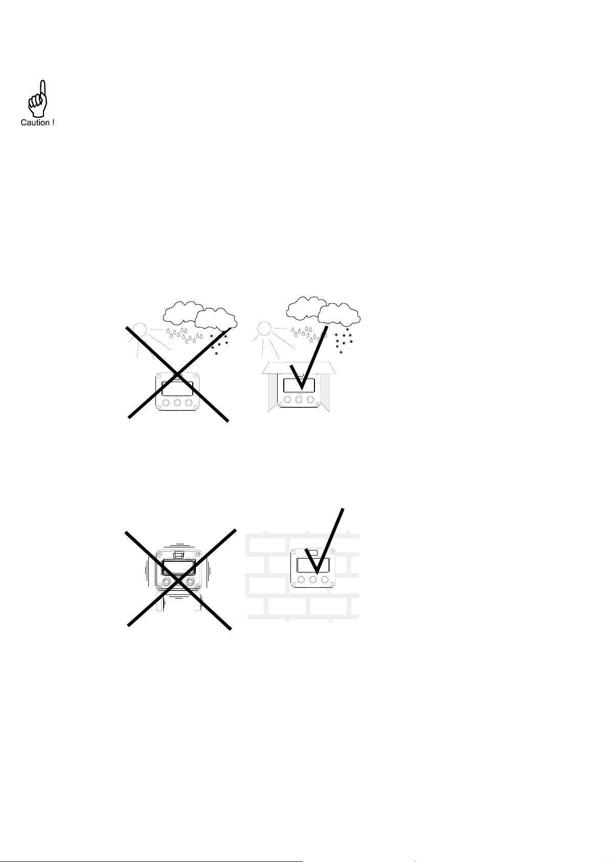
4.2. INSTALLATION / SURROUNDING CONDITIONS
Take the relevant IP classification of the casing into account (see manufactures plate). Even an IP67
(NEMA 4X) casing should NEVER be exposed to strongly varying (weather) conditions.
When panel-mounted, the unit is IP65 (NEMA 4X)!
When used in very cold surroundings or varying climatic conditions, take the necessary precautions
against moisture by placing a dry sachet of silica gel, for example, inside the instrument case.
Mount the F197-A on a solid structure to avoid vibrations.
Table of contents
Popular Inverter manuals by other brands


Victron energy
Victron energy Quattro 12/5000/220-100|100-230V manual

Tsun
Tsun TSOL-ACU3.0K user manual

Generac Power Systems
Generac Power Systems 00802-3 Installation and owner's manual

Sungrow
Sungrow SG50KTL-M installation guide

Thinkpower
Thinkpower EPH4KTL user manual

Hoppecke
Hoppecke AquaGen Instructions for use