manuals.online logo
Brands
  1. Home
  2. •
  3. Brands
  4. •
  5. Goodwe
  6. •
  7. Inverter
  8. •
  9. Goodwe DS SERIES User manual

Goodwe DS SERIES User manual

User Manual
GOODWE DS SERIES
Ver 01
Table of Contents
1 Symbols . . . . . . . . . . . . . . . . . . . . . . . . . . . . . . . . . . . . . 01
2 Safety . . . . . . . . . . . . . . . . . . . . . . . . . . . . . . . . . . . . . . . 02
3 Installation . . . . . . . . . . . . . . . . . . . . . . . . . . . . . . . . . . . 04
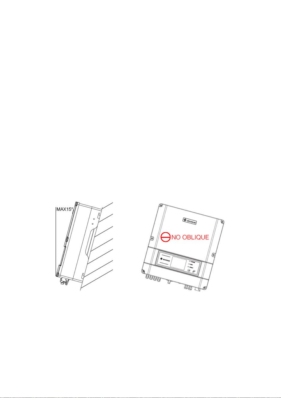
3.1 Mounting Instruction . . . . . . . . . . . . . . . . . . . . . . . . . 04
3.2 Unpacking . . . . . . . . . . . . . . . . . . . . . . . . . . . . . . . . . 04
3.3 Equipment Installation . . . . . . . . . . . . . . . . . . . . . . . . 06
3.4 Electrical Connection . . . . . . . . . . . . . . . . . . . . . . . . . 10
3.5 Troubleshooting . . . . . . . . . . . . . . . . . . . . . . . . . . . . . 24
4 System Operation . . . . . . . . . . . . . . . . . . . . . . . . . . . . . . 27
4.1 Display . . . . . . . . . . . . . . . . . . . . . . . . . . . . . . . . . . . 27
4.2 Indicator Lights . . . . . . . . . . . . . . . . . . . . . . . . . . . . . 27
4.3 LCD display . . . . . . . . . . . . . . . . . . . . . . . . . . . . . . . 28
4.4 Error Message . . . . . . . . . . . . . . . . . . . . . . . . . . . . . . 36
4.5 ID Reset . . . . . . . . . . . . . . . . . . . . . . . . . . . . . . . . . . . 38
5 Technical Parameters . . . . . . . . . . . . . . . . . . . . . . . . . . . 39
GW3600-DS GW4200-DS GW4600-DS . . . . . . . . . . . . . 39
GW3600D-DK/UK . . . . . . . . . . . . . . . . . . . . . . . . . . . . . . 42
6 Certificates . . . . . . . . . . . . . . . . . . . . . . . . . . . . . . . . . . . 45
7 Warranty . . . . . . . . . . . . . . . . . . . . . . . . . . . . . . . . . . . . 46
7.1 Warranty Period . . . . . . . . . . . . . . . . . . . . . . . . . . . . . 46
7.2 Warranty Card . . . . . . . . . . . . . . . . . . . . . . . . . . . . . . 46
7.3 Warranty Conditions . . . . . . . . . . . . . . . . . . . . . . . . . 46
7.4 Scope of Warranty . . . . . . . . . . . . . . . . . . . . . . . . . . . 47
8 Contact . . . . . . . . . . . . . . . . . . . . . . . . . . . . . . . . . . . . . . 48
Notes:
The pictures in this manual are for reference only, please
be subject to the real product.
- 1 -
1 Symbols
Caution! - Failure to observe a warning indicated in this
manual may result in minor or moderate injury
Danger of high voltage and electric shock!
Danger of hot surface!
Product should not be disposed as normal household
waste.
This side up- The package must always be transported,
handled and stored in such a way that the arrows always
point upwards.
Components of the product can be recycled.
Fragile-The package/product should be handled carefully
and never be tipped over or slung.
Stack limitation 6 units of identical packages that may be
stacked in maximum.
Keep dry – The package/product must be protected from
excessive humidity and must accordingly be stored under
cover.
CE Mark
Residual voltage exists in the inverter; the inverter cannot
be maintained within 5 minutes until the capacitor is fully
discharged
- 2 -
Units:
2 Safety
DS series inverter of Jiangsu GoodWe Power Supply Technology
Co.,Ltd. ( hereinafter referred to as GoodWe ) strictly conforms to
related safety rules in design and test. As electric and electronic
equipment, Safety Regulation shall be followed during installation
and maintenance. Improper operation may bring severe damage to
the operator, the third party and other properties.
`The installation and maintenance of the inverters must be
performed by qualified personnel only in compliance with
national and local standards and regulations.
`Before installation and maintenance, DC input and AC output of
the inverter should be cut off beforehand and the inverter cannot
be touched within 10 minutes after power cut-off in case of
electric shock.
`Partial temperature of the inverter may exceed 60Ԩduring
- 3 -
operation, please do not touch in case of scalding.
`All electric installation should conform to local electric standard
and permission has to be obtained from local power supply
department before synchronization by qualified personnel.
`Children must be kept away from inverters.
`Please do not open the front cover of inverter. Apart from wiring
terminal, touching or changing components without
authorization may cause damage to people and inverters.
GoodWe may deny the obligation of warranty service
accordingly.
`Static electricity may damage electronic components and proper
measures shall be adopted to avoid static electricity.
`The output voltage of proposed PV array should be lower than
the inverter maximum rated input voltage; otherwise, GoodWe
will not undertake any obligations and warranty services.
- 4 -
3 Installation
3.1 Mounting Instruction
A In order to achieve optimal performance, the ambient
temperature should be lower than 45 °C.
B For the convenience of checking the LCD display and
possible maintenance activities, please install the inverter at
eye level.
C Inverters should NOT be installed near inflammable and
explosive items. Any electro-magnetic equipment should be
kept away from installation site.
D Product label and warning symbol shall be clear to read after
installation.
3.2 Unpacking
When you receive GoodWe inverter, please check if there is any
visible external damage on the inverter or any accessories. Please
also check if there is anything missing according to the list below.
Inverter . . . . . . . . . . . . . . . . . . . . . . . . . . . . . . . . . . . . 1
Wall-mounted bracket . . . . . . . . . . . . . . . . . . . . . . . . . 1
Lock Plate . . . . . . . . . . . . . . . . . . . . . . . . . . . . . . . . . . 1
Positive DC Plug . . . . . . . . . . . . . . . . . . . . . . . . . . . . . 4
Negative DC Plug . . . . . . . . . . . . . . . . . . . . . . . . . . . . . 4
AC Plug . . . . . . . . . . . . . . . . . . . . . . . . . . . . . . . . . . . 1
USB Data Cable . . . . . . . . . . . . . . . . . . . . . . . . . . . . . 1
- 5 -
Expansion Bolt . . . . . . . . . . . . . . . . . . . . . . . . . . . . . . 7
Flat Head Screw for Lock Plate and RS485 Cover. . . . . . 5
User Manual . . . . . . . . . . . . . . . . . . . . . . . . . . . . . . . . 1
Warranty Card . . . . . . . . . . . . . . . . . . . . . . . . . . . . . . . 1
Wall-mounted
Bracket Positive DC Plug Negative DC Plug
Lock Plate
AC Plug
USB Data Cable
Expansion Bolt
Inverter
Flat Head Screw User Manual
Warranty Card
- 6 -
3.3 Equipment Installation
3.3.1 Selecting the installation position
Installation position should be selected based on the following
aspects:
`The installation method and mounting location must be suitable
for the inverter's weight and dimensions.
`Mount on a solid surface.
`Select a well ventilated place sheltered from direct sun radiation.
`Install vertically or tilted backward by max 15°. The device
cannot be installed with a sideways tilt. The connection area
must point downwards.
Figure 3.3.1-1
- 7 -
`In consideration of heat dissipation and convenient
dismantlement, the minimum clearances around the inverter
should be no less than the following value:
Upward . . . . . . . . . . . . . . . . . . . . . . . . . . . . . . . 300mm
Downward . . . . . . . . . . . . . . . . . . . . . . . . . . . . 500mm
Front . . . . . . . . . . . . . . . . . . . . . . . . . . . . . . . . 300mm
Both sides . . . . . . . . . . . . . . . . . . . . . . . . . . . . . 200mm
Figure 3.3.1-2
3.3.2 Mounting Procedure
AUse the wall-mounted bracket as a template and drill 7 holes
on the wall, 10 mm in diameter and 80 mm deep.
- 8 -
Figure 3.3.2-1
BFix the wall mounting bracket on the wall with the expansion
bolts in accessory bag.
CCarry the inverter by holding the groove on the heat sink.
Figure 3.3.2-2
DPlace the inverter on the wall-mounted bracket (as illustrated
below).
- 9 -
Figure 3.3.2-3 Figure 3.3.2-4
Figure 3.3.2-5
E Insert lock plate into two holes in the heat-sink, then fix the
inverter with a padlock and screw M3x8
Figure 3.3.2-6
- 10 -
3.4 Electrical Connection
You must comply with the connection requirement of local
regulations.
The inverter is integrate with an RCMU according to VDE0126-
1-1/A1. It monitors residual current from the solar module to grid
side of inverter. The inverter can automatically differentiate
between fault current and normal capacitive leakage currents.
3.4.1 Connection to grid (AC side Connection)
ACheck the grid (utility) voltage and frequency at the
connection point of the inverter. It should be 230VAC (or
220VAC), 50/60Hz, and single phase.
BDisconnect the breaker or fuse between PV-Inverter and utility.
CConnect the inverter to the grid as follows:
`Switch off the AC Breaker.
`Disassemble female connector of the AC wire connector
and connectAC wires to connection socket as indicated.
Figure 3.4.1-1
- 11 -
`Insert Line wire to Pin 1, Neutral wire to Pin 2 and Ground
wire to Pin
Figure 3.4.1-2
`After fastening all screws, reassemble the female
connector of the AC wire connector.
`Connect the female connector of the AC wire connector to
the Male connector on the inverter.
DSpecifications of the AC wires:
Figure 3.4.1-3
- 12 -
Depiction Size
A External diameter of the wire 12mm-25mm
B Sectional area of conducting materials Max.6mm2
C Length of bare wire Approx.10mm
E AC output connection diagram
Please tighten the screw with a screw driver until the head of the
screw is inside the connector. Otherwise the wire could be loose.
Figure 3.4.1-4
3.4.2 DC side connection
AMake sure the maximum open circuit voltage (Voc) of each PV
string does not exceed the inverter input voltage Vmax under
any condition.
BUse Phoenix contact or Multi-contact connectors for PV array
terminals.
CConnect the positive and negative terminals of the PV panel to
corresponding terminals on the Inverter. The DC terminal on
each Inverter can bear 20A DC current.
- 13 -
If use Phoenix contact connectors for PV array terminals,
installation as follows.
Female side connector (PV+) Male side connector (PV-)
Both types of connectors must be equipped in pair strictly
according to above graphs
Figure 3.4.2-1
Figure 3.4.2-2
1. Insert the stripped PV conductor
- 14 -
Figure 3.4.2-3
2. Press down on the spring and snap in
Figure 3.4.2-4
3.Tighten the screw connection then the terminal can be connected
to the inverter side
- 15 -
Figure 3.4.2-5
Can only be released using a screwdriver
If use Multi-contact connectors for PV array terminals, installation
as follows.
Female side connector (PV+) Male side connector (PV-)
Both types of connectors must be equipped in pair strictly
according to above graphs
- 16 -
- 17 -
Figure 3.4.2-6
Tighten the screw connection then the terminal can be connected to
the inverter side
Figure 3.4.2-7
Compress the two snap-in springs by hand and release
Regarding the inverter equiped with DC switch, please ensure the
switch is in "OFF" position before connecting the inverter with PV
panels. Then switch to "ON" when connecting job is done.

- 18 -
`Before connecting the PV panels, please ensure the plug
connectors have the correct polarity. Incorrect polarity
connection could permanently damage the unit.
`Checks short-circuit current of the PV string. The total short-
circuit current of the PV string cannot exceed the inverter’s
maximum DC current.
`High voltage exists when the PV panel is exposed to the sun.
Please secure the terminal connection, and do NOT touch any
exposed components in case of electric shock.
3.4.3 RS485 Communication
RS485 interface is used for multipoint communication. EzLogger
can monitor and communicate with 50 inverters at the same time.
But the maximum length of the cable should not exceed 1000 m.
All the inverters, which communicate through one cable, should
use provided RS485 interface (a piece of 10# cable is recommend
to be connected for waterproofing without RS485 cable
connection). The typical inverter connection graph through RS485
is shown below.

This manual suits for next models

5

Other Goodwe Inverter manuals

Goodwe GW5000-MS-30 User manual

Goodwe

Goodwe GW5000-MS-30 User manual

Goodwe GW8KAU-DT User manual

Goodwe

Goodwe GW8KAU-DT User manual

Goodwe GW9900-MS-30 User manual

Goodwe

Goodwe GW9900-MS-30 User manual

Goodwe SCB2000 User manual

Goodwe

Goodwe SCB2000 User manual

Goodwe SBP SERIES User manual

Goodwe

Goodwe SBP SERIES User manual

Goodwe XS Series User manual

Goodwe

Goodwe XS Series User manual

Goodwe A-BP Series User manual

Goodwe

Goodwe A-BP Series User manual

Goodwe GW9.9KAU-DT User manual

Goodwe

Goodwe GW9.9KAU-DT User manual

Goodwe SDT SERIES User manual

Goodwe

Goodwe SDT SERIES User manual

Goodwe DNS Series User manual

Goodwe

Goodwe DNS Series User manual

Goodwe ES Series User manual

Goodwe

Goodwe ES Series User manual

Goodwe HT 73-136kW Series User manual

Goodwe

Goodwe HT 73-136kW Series User manual

Goodwe SDT G2 Series User manual

Goodwe

Goodwe SDT G2 Series User manual

Goodwe ETC Series User manual

Goodwe

Goodwe ETC Series User manual

Goodwe ES Series User manual

Goodwe

Goodwe ES Series User manual

Goodwe UT Series User manual

Goodwe

Goodwe UT Series User manual

Goodwe XS Series User manual

Goodwe

Goodwe XS Series User manual

Goodwe MT series User manual

Goodwe

Goodwe MT series User manual

Goodwe EH Series User manual

Goodwe

Goodwe EH Series User manual

Goodwe ES Series User manual

Goodwe

Goodwe ES Series User manual

Goodwe GW3648D-ES User manual

Goodwe

Goodwe GW3648D-ES User manual

Goodwe ETC Series User manual

Goodwe

Goodwe ETC Series User manual

Goodwe GW5048-ESA User manual

Goodwe

Goodwe GW5048-ESA User manual

Goodwe EH Series User manual

Goodwe

Goodwe EH Series User manual

Popular Inverter manuals by other brands

Dass Soleaf DSP-123JB-OD Operation and installation

Dass

Dass Soleaf DSP-123JB-OD Operation and installation

GÜDE GIS 160 WIG/HF Translation of the original instructions

GÜDE

GÜDE GIS 160 WIG/HF Translation of the original instructions

ABB UNO-DM-1.2-TL-PLUS-Q Quick installation guide

ABB

ABB UNO-DM-1.2-TL-PLUS-Q Quick installation guide

Fuji Electric FRENIC-Multi Starting guide

Fuji Electric

Fuji Electric FRENIC-Multi Starting guide

Mecc Alte ECO-ECP 4 Operating and maintenance instructions

Mecc Alte

Mecc Alte ECO-ECP 4 Operating and maintenance instructions

ANDELI TIG-250PL ACDC Operator's manual

ANDELI

ANDELI TIG-250PL ACDC Operator's manual

Magnum MMG25FHI operating manual

Magnum

Magnum MMG25FHI operating manual

Guardian QuietSource 005336-1 owner's manual

Guardian

Guardian QuietSource 005336-1 owner's manual

HERKULES SE 5500 SF operating instructions

HERKULES

HERKULES SE 5500 SF operating instructions

Mastervolt WHISPER 16 ULTRA user manual

Mastervolt

Mastervolt WHISPER 16 ULTRA user manual

AIMS Power PICOGLF6W12V120V user manual

AIMS Power

AIMS Power PICOGLF6W12V120V user manual

Airwell AW-YHDM012-H91 Service manual

Airwell

Airwell AW-YHDM012-H91 Service manual

Ideal Clima COMFOSPLIT IKARO User's and installer's manual

Ideal Clima

Ideal Clima COMFOSPLIT IKARO User's and installer's manual

Westerbeke 15.0BTD60-HERTZ Operator's manual

Westerbeke

Westerbeke 15.0BTD60-HERTZ Operator's manual

SMA SUNNY BOY STORAGE 2.5 Quick reference guide

SMA

SMA SUNNY BOY STORAGE 2.5 Quick reference guide

Mitsubishi Electric FR-HEL-C75K instruction manual

Mitsubishi Electric

Mitsubishi Electric FR-HEL-C75K instruction manual

Power Electronics SD700FL Series Hardware and installation manual

Power Electronics

Power Electronics SD700FL Series Hardware and installation manual

SMA SHP 100-20 operating manual

SMA

SMA SHP 100-20 operating manual

manuals.online logo
manuals.online logoBrands
  • About & Mission
  • Contact us
  • Privacy Policy
  • Terms and Conditions

Copyright 2025 Manuals.Online. All Rights Reserved.