manuals.online logo
Brands
  1. Home
  2. •
  3. Brands
  4. •
  5. Fluidwell
  6. •
  7. Measuring Instrument
  8. •
  9. Fluidwell B Series User manual

Fluidwell B Series User manual

B-ALERT
Flowrate monitor / totalizer
Quick Reference Guide
B-Series - Basic with a capital B
More info: www.fluidwell.com
1. INTRODUCTION
The B-Series are intended for use in safe areas (ordinary locations)
and designed and constructed for measurement purposes in
industrial processes. A hazardous situation may occur if the B-
Series is not used for the purpose it was designed for or is used
incorrectly.
2. DESCRIPTION
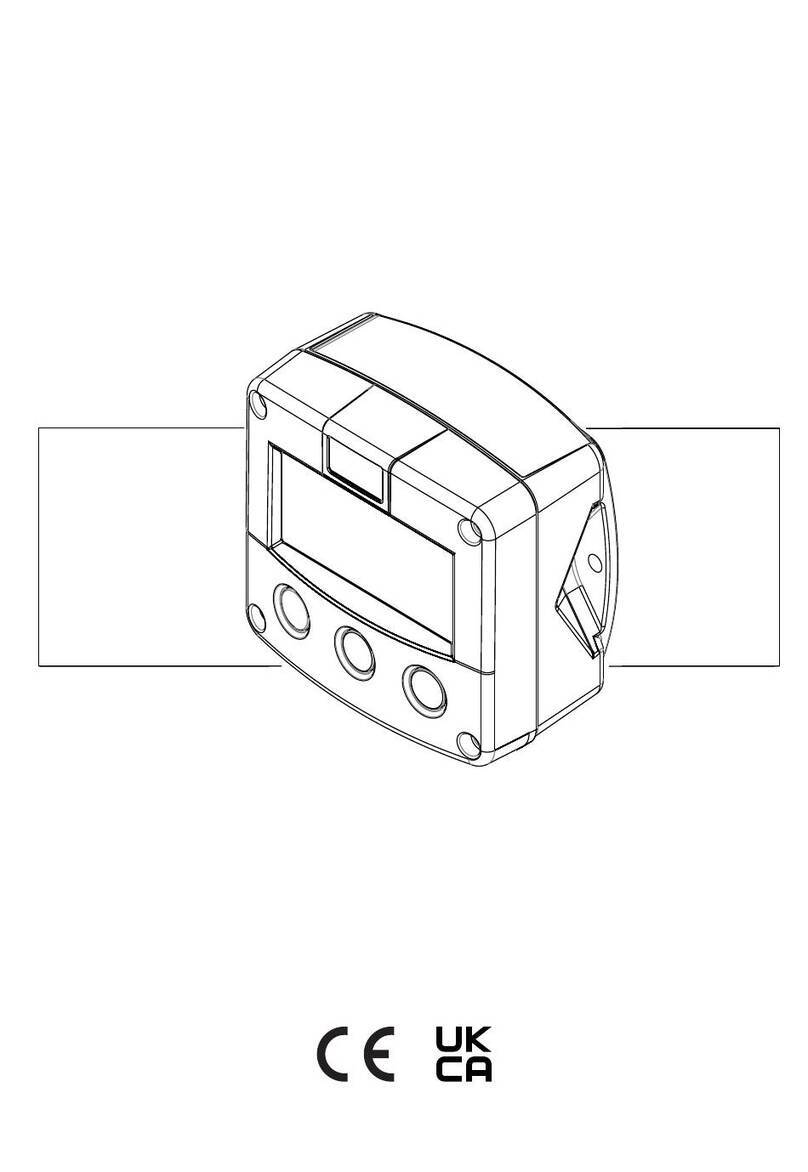
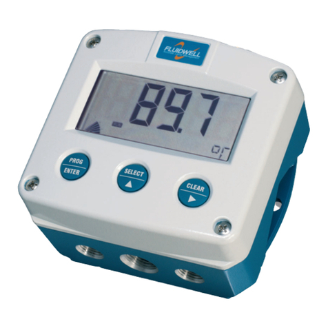
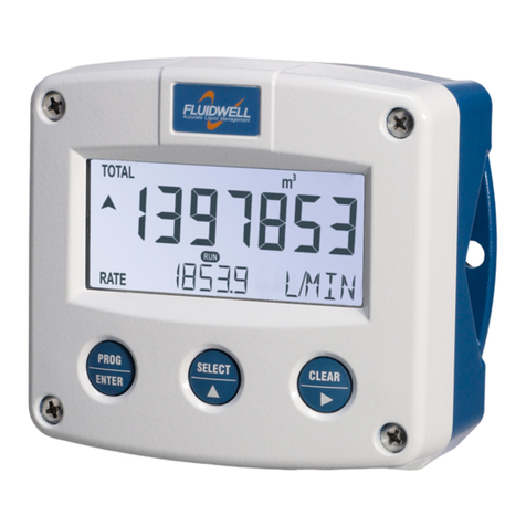
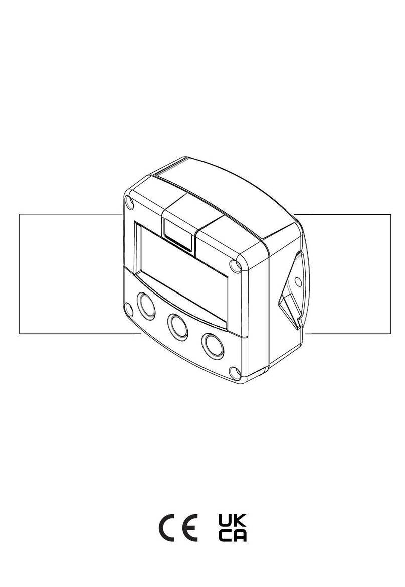
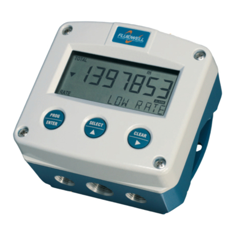
The B-Alert is used as a flowrate monitor and indicator / totalizer
and has one flowmeter input and two alarm or scaled pulse outputs.
B-Series components:
•the front cover (3) with the display (5) and the control keys (4);
•the body (1) with knockouts for the cable glands (2).
4. NAVIGATION IN SETUP MENU
The setup menu has menus (e.g. 1, 2 and 3) and sub-menus
(e.g. 2.1, 2.2 etc.) to configure the B-Series.
Enter / leave setup: press and hold SELECT 7 seconds
Select a menu: press CLEAR
Select a sub-menu: press SELECT
Change selection:
➢simultaneously, press SELECT + CLEAR.
➢press SELECT to increase value en RESET to
select the digit or change the selection.
Confirm change: simultaneously press SELECT + CLEAR
MORE INFORMATION
Downloads:
•Detailed user-manual
•EU Declaration of Conformity (DoC),
by scanning the QR-code:
or visit our website:
www.fluidwell.com/bseries.
Fluidwell bv
Voltaweg 23
5466 AZ Veghel - The
Netherlands
www.fluidwell.com
Doc: B-Alert_QRG_02.docx
This publication is subject to change without prior notice.
3. OPERATION
SELECT-key
to view the Flowrate, Total, Accumulated total, alarm
value low and high flowrate.
CLEAR-key
when in the Total screen, to reset (clear) the Total.
Programming flowrate alarm value:
1. Press the SELECT key to view the ALARM screen.
2. Simultaneously, press SELECT + CLEAR.
3. Press SELECT to increase value and CLEAR to select digit.
4. Confirm change: simultaneously press SELECT + CLEAR
You can reset (clear) the Total:
1. Press the SELECT key to view the Total screen.
2. Press the CLEAR key two times.
Examples display information:
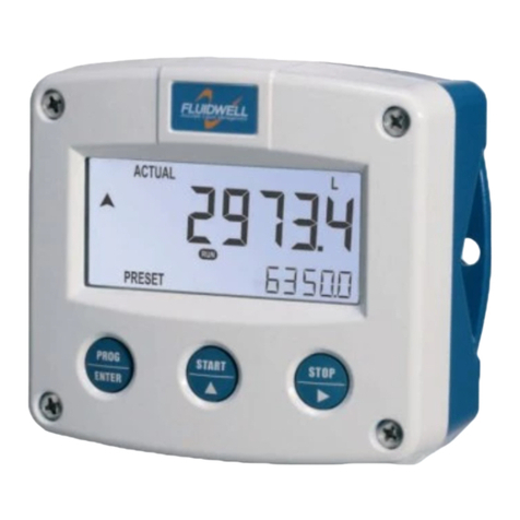
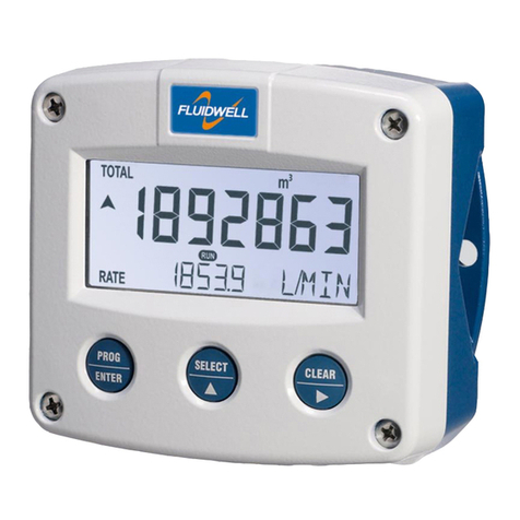
Flowrate
Programming low flowrate alarm
5. SETUP MENU STRUCTURE
1.
1.1
1.2
1.3
1.4
2.
2.1
2.2
2.3
2.4
2.5
2.6
3.
3.1
3.2
3.3
4.
4.1
TOTAL
Unit
Decimals
K-Factor
K-Factor decimals
RATE
Unit
Time unit
Decimals
K-Factor
K-Factor decimals
Measurement
ALARM
Zero
Low alarm
High Alarm
METER
Signal
5.
5.1
5.2
5.3
5.4
5.5
6.
6.1
6.2
6.3
6.4
6.5
DIGITAL OUT
Output 1
output 2
Mode
Decimals
Amount
OTHER
Model
Software version
Serial number
Pin code
Backlight
GENERAL SAFETY INFORMATION
This safety information is meant for guidance. Consult the full
user-manual for all detailed safety instructions, safety rules and
precautionary measures. The employer's and the plant owner’s
safety instructions shall always prevail.
•It is the responsibility of the installer to install the B-Series in
accordance with the (inter)national Rules and Regulations.
The manufacturer accepts no responsibility whatsoever if the
instructions as described in this publication are not followed.
•Only qualified and well-trained persons are allowed to install,
operate, maintain and service the B-Series.
•Read this publication and take note of the technical
specifications of the B-Series and related peripheral devices.
•Do not touch the electronics. Electro Static Discharge (ESD)
can cause serious damage to the electronics! Take the
ESD-precautionary measures before you open the B-Series.
•It is not allowed to modify or change the B-Series without a
written authorization from the manufacturer.
•The B-Series must be installed in accordance with the
(inter)national Rules and Regulations. Make sure, the
connections and settings are made correctly.
Before doing any work: make sure all leads are de-energized.
7. GENERAL TECHNICAL SPECIFICATIONS
Sensor: Coil (30mVpp); Reed; NPN; PNP; NAMUR
Rating: IP65
Ambient: -20°C to +60°C (-4°F to +140°F)
Note: Protect against severe weather and direct sunlight!
Humidity: 90%, no condensation allowed
Wire gauge: stranded 0.25-1 mm2, solid 0.14-1.5 mm2, AWG 26-16
Terminal, Torque: M2, 0.22 - 0.25 Nm
Material: GRP enclosure, Polyester window
Weight: 200g
BATTERY SAFETY INSTRUCTION
The batteries are used to store electrical energy. The battery is
a high power battery which must be treated carefully. When
the battery is mistreated or damaged, there is a risk of a fire,
an explosion and serious burns.
•Only use a battery which is applicable for the intended use.
•Mind that you cannot switch off a battery.
•Make sure, it is safe to work on the battery system.
•Handle the battery with the utmost care to prevent a short
circuit and damage.
•Do not recharge, crush, disassemble, incinerate, heat above
its rated temperature or expose to water.
•Dispose of the battery in accordance with the (inter)national
and the plant owner’s standards and regulations.
BATTERY SPECIFICATION
Primary, non-rechargeable, Lithium metal Thionyl Chloride
(Li/SOCl2), 1x3.6V/2.4Ah, AA size (IEC-R6, ANSI size15).
6. INSTALLATION
1.Install the body with the screws to the wall.
2.Make sure, the O-ring is installed correctly.
3.Install the wiring as applicable.
4.Connect the wiring according the terminal layout.
5.If applicable, install the battery.
6.Mind the O-ring! Install the cover with the bolts.
The rear-enclosure part can be rotated in steps of 90°, enabling
cable entry from any side.
8. TERMINAL CONNECTIONS
1, 2
Pulse signal from flowmeter
3
No real sensor supply, low power only! Imax: 100µA
4
8.2V DC sensor supply; Imax: 10mA.
5, 6
Passive transistor output; max. 300mA - 30V
7, 8
Passive transistor output; max. 300mA - 30V
9, 10
External power supply, max. consumption 735mW
9. CHANGE THE BATTERY
a.Obey the battery safety instruction.
b.Open the B-Series, remove and keep the bolts (1).
c.Hold the cover (2) and carefully remove the battery (3).
d.Inspect the battery holder (4) for signs of deterioration.
e.Mind the polarity! Install a new battery (3) in the holder (4).
f. Make sure, the display comes on.
g.Install the cover (2) with the bolts (1).
F: 52mm (2.05”)
G: 72mm (2.83”)
H: 19mm (0.75”)
J: 38mm (1.49”)
A/B: 92mm (3.62”)
C/A:60mm (2.36”)
D/E: 14mm (0.55”)
Note: Input, outputs & power supply
use a common ground.
This manual suits for next models

1

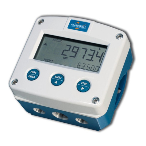
Other Fluidwell Measuring Instrument manuals

Fluidwell F013-A User manual

Fluidwell

Fluidwell F013-A User manual

Fluidwell F115-P User manual

Fluidwell

Fluidwell F115-P User manual

Fluidwell F115-P User manual

Fluidwell

Fluidwell F115-P User manual

Fluidwell F110-A User manual

Fluidwell

Fluidwell F110-A User manual

Fluidwell F040-U User manual

Fluidwell

Fluidwell F040-U User manual

Fluidwell D Series User manual

Fluidwell

Fluidwell D Series User manual

Fluidwell F Series User manual

Fluidwell

Fluidwell F Series User manual

Fluidwell D090-A-PL User manual

Fluidwell

Fluidwell D090-A-PL User manual

Fluidwell F110-A User manual

Fluidwell

Fluidwell F110-A User manual

Fluidwell F Series User manual

Fluidwell

Fluidwell F Series User manual

Fluidwell F126-P-EG-TP User manual

Fluidwell

Fluidwell F126-P-EG-TP User manual

Fluidwell E Series Operation instructions

Fluidwell

Fluidwell E Series Operation instructions

Fluidwell F Series User manual

Fluidwell

Fluidwell F Series User manual

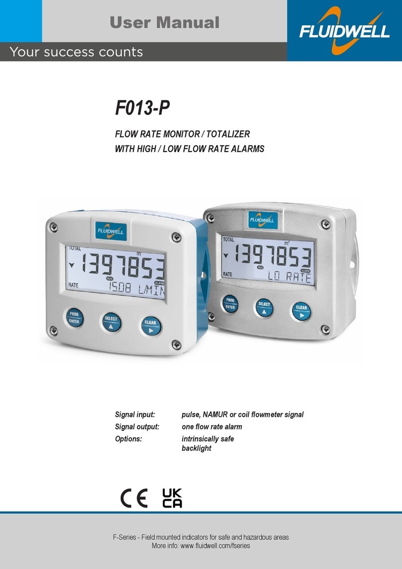
Fluidwell F013-P User manual

Fluidwell

Fluidwell F013-P User manual

Fluidwell F053-A User manual

Fluidwell

Fluidwell F053-A User manual

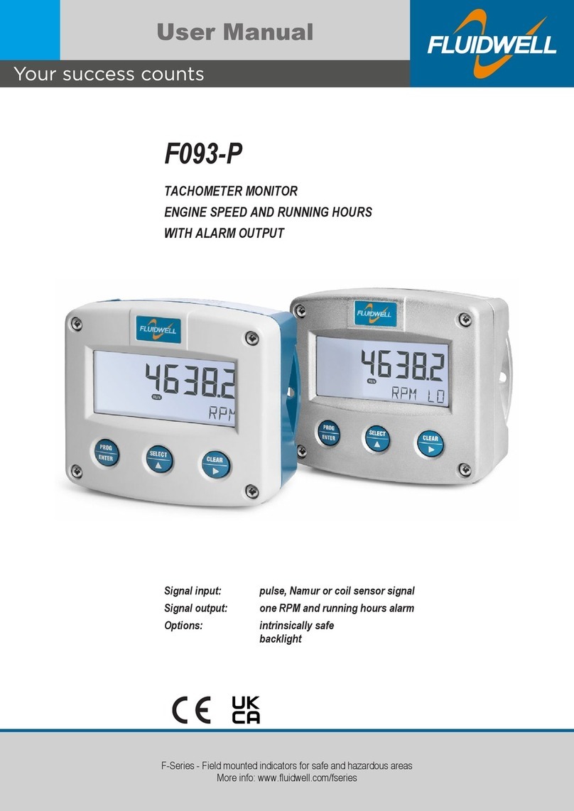
Fluidwell F093-P User manual

Fluidwell

Fluidwell F093-P User manual

Fluidwell F Series User manual

Fluidwell

Fluidwell F Series User manual

Fluidwell F127-P-EL-TP User manual

Fluidwell

Fluidwell F127-P-EL-TP User manual

Fluidwell F053-U User manual

Fluidwell

Fluidwell F053-U User manual

Fluidwell F118-A User manual

Fluidwell

Fluidwell F118-A User manual

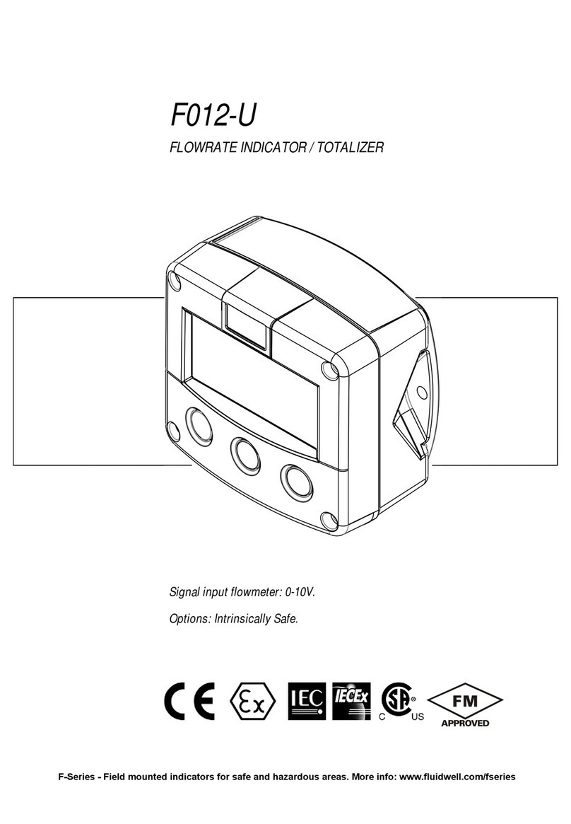
Fluidwell F012-U User manual

Fluidwell

Fluidwell F012-U User manual

Fluidwell F115-P User manual

Fluidwell

Fluidwell F115-P User manual

Fluidwell F127-P-EL-TA User manual

Fluidwell

Fluidwell F127-P-EL-TA User manual

Fluidwell F1-A-PD-OS Series User manual

Fluidwell

Fluidwell F1-A-PD-OS Series User manual

Popular Measuring Instrument manuals by other brands

SMA STRING-MONITOR SSM-U-2410 technical information

SMA

SMA STRING-MONITOR SSM-U-2410 technical information

THORLABS MCLS Series operating manual

THORLABS

THORLABS MCLS Series operating manual

RIDGID micro LM-100 manual

RIDGID

RIDGID micro LM-100 manual

Polytec OFV-3001 user manual

Polytec

Polytec OFV-3001 user manual

PCB Piezotronics ICP 337A31 Installation and operating manual

PCB Piezotronics

PCB Piezotronics ICP 337A31 Installation and operating manual

IFM SM6x04 operating instructions

IFM

IFM SM6x04 operating instructions

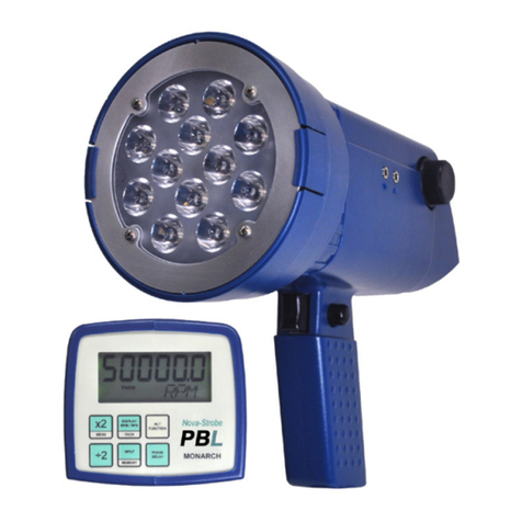
MONARCH INSTRUMENT Nova-Strobe PBL instruction manual

MONARCH INSTRUMENT

MONARCH INSTRUMENT Nova-Strobe PBL instruction manual

wtw inoLab Oxi Level 2 operating manual

wtw

wtw inoLab Oxi Level 2 operating manual

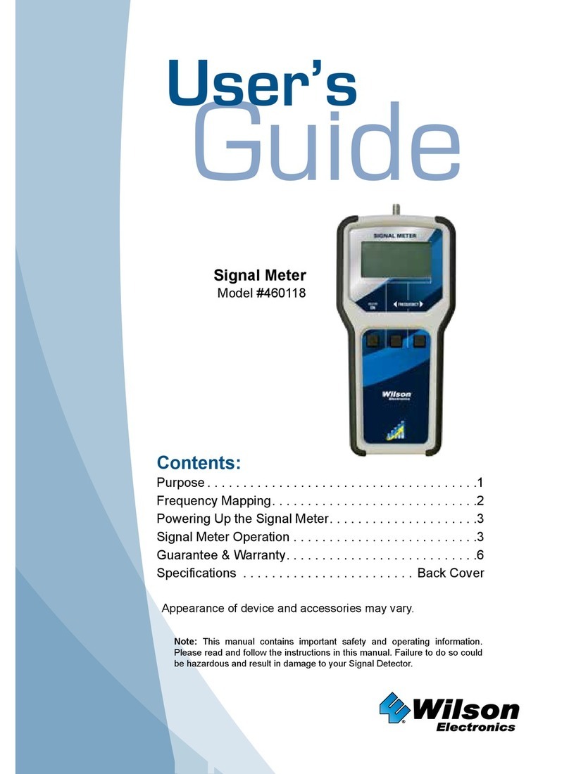
Wilson Electronics 460118 user guide

Wilson Electronics

Wilson Electronics 460118 user guide

HunterLab Vista Supplemental manual

HunterLab

HunterLab Vista Supplemental manual

PCB Piezotronics 1102-05A Installation and operating manual

PCB Piezotronics

PCB Piezotronics 1102-05A Installation and operating manual

NI PXIe-5624R CALIBRATION PROCEDURE

NI

NI PXIe-5624R CALIBRATION PROCEDURE

SUPMEA SUP-5000C user manual

SUPMEA

SUPMEA SUP-5000C user manual

Elma 1350C user manual

Elma

Elma 1350C user manual

EKO Instruments MS-212W instruction manual

EKO Instruments

EKO Instruments MS-212W instruction manual

HP 8555A Operating and service manual

HP

HP 8555A Operating and service manual

Laserworld Ecoline Series manual

Laserworld

Laserworld Ecoline Series manual

AEMC 500 user manual

AEMC

AEMC 500 user manual

manuals.online logo
manuals.online logoBrands
  • About & Mission
  • Contact us
  • Privacy Policy
  • Terms and Conditions

Copyright 2025 Manuals.Online. All Rights Reserved.