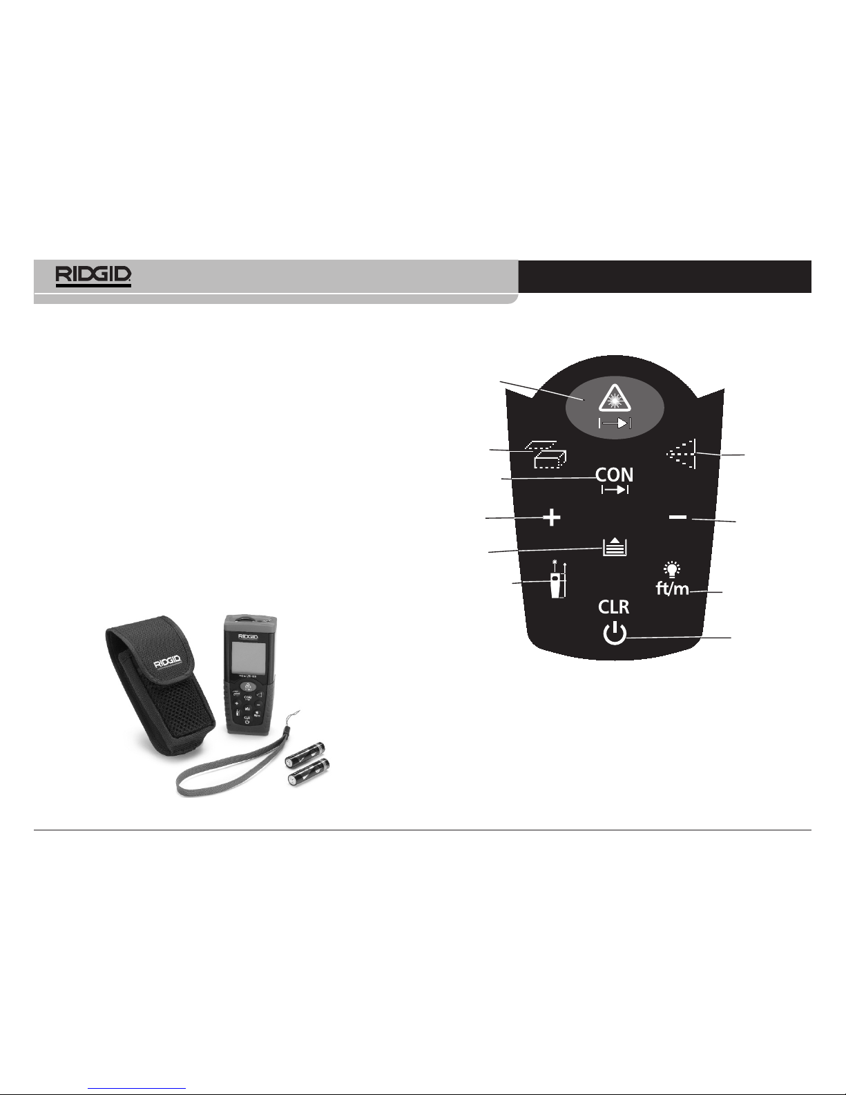
micro LM-100 Laser Distance Meter
Ridge Tool Company
4
•Use personal protective equipment. Always wear eye protec-
tion. Protective equipment such as dust mask, non-skid safety
shoes, hard hat, or hearing protection used for appropriate con-
ditions will reduce personal injuries.
•
Do not overreach. Keep proper footing and balance at all
times. This enables better control of the power tool in unexpected
situations.
Equ pment Use and Care
•Do not force equipment. Use the correct equipment for your
application. The correct equipment will do the job better and
safer at the rate for which it is designed
•Do not use equipment if the switch does not turn it O and
OFF. Any tool that cannot be controlled with the switch is danger-
ous and must be repaired.
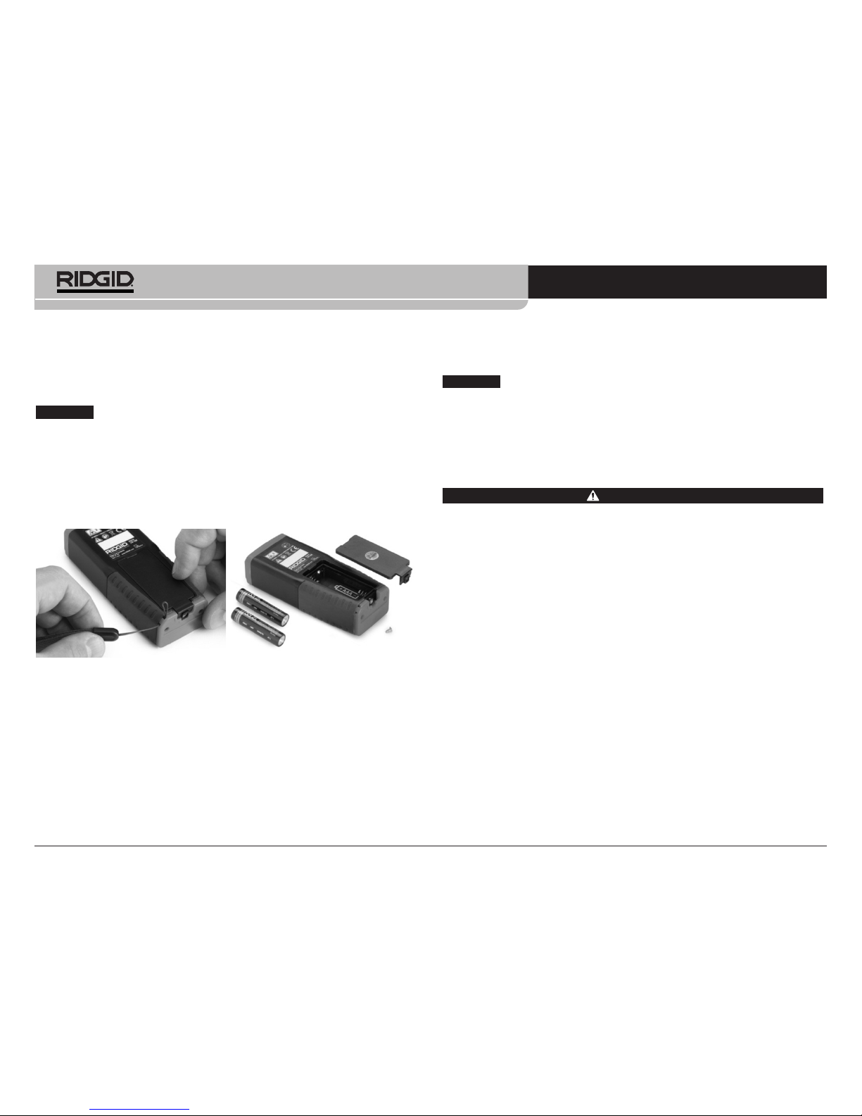
•Disconnect the batteries from the equipment before making
any adjustments, changing accessories, or storing. Such
preventive safety measures reduce the risk of injury.
•Store idle equipment out of the reach of children and do not
allow persons unfamiliar with the equipment or these in-
structions to operate the equipment. Equipment can be dan-
gerous in the hands of untrained users.
•Maintain equipment. Check for misalignment or binding of mov-
ing parts, missing parts, breakage of parts and any other condi-
tion that may affect the equipment’s operation. If damaged, have
the equipment repaired before use. Many accidents are caused
by poorly maintained equipment
•Use the equipment and accessories in accordance with
these instructions, taking into account the working condi-
tions and the work to be performed. Use of the equipment for
operations different from those intended could result in a haz-
ardous situation
General Safety Rules
WARNING
Read all safety warn ngs and nstruct ons. Fa lure to follow the
warn ngs and nstruct ons may result n electr c shock, f re
and/or ser ous njury.
SAVE THESE INSTRUCTIONS!
The CE declaration of comformity (890-011-320) will accompany
this manual as a separate booklet when required.
Work Area Safety
•Keep your work area clean and well lit. Cluttered or dark areas
invite accidents.
•Do not operate equipment in explosive atmospheres, such
as in the presence of flammable liquids, gases, or dust.
Equipment can create sparks which may ignite the dust or fumes
•Keep children and by-standers away while operating equip-
ment. Distractions can cause you to lose control.
Electr cal Safety
•
Avoid body contact with earthed or grounded surfaces such as
pipes, radiators, ranges and refrigerators. There is an increased
risk of electrical shock if your body is earthed or grounded.
•Do not expose equipment to rain or wet conditions. Water
entering equipment will increase the risk of electrical shock.
Personal Safety
•Stay alert, watch what you are doing and use common
sense when operating equipment. Do not use equipment
while you are tired or under the influence of drugs, alcohol
or medication. A moment of inattention while operating equip-
ment may result in serious personal injury.