Polytec OFV-3001 User manual

Title
User Manual
Laser Doppler Vibrometer
Controller OFV-3001
Sensor Heads OFV-303/-353
OFV-511/-512
Advanced Test Equipment Rentals
www.atecorp.com 800-404-ATEC (2832)
®
E
s
t
a
b
l
i
s
h
e
d
1
9
8
1

Warranty and Service
The warranty for this equipment complies with the regulations in our general terms and
conditions in their respective valid version.
This is conditional on the equipment being used as it is intended and as described in this
manual.
The warranty does not apply to damage caused by incorrect usage, external mechanical
influences or by not keeping to the operating conditions. The warranty also is invalidated in the
case of the equipment being tampered with or modified without authorization.
To return the equipment always use the original packaging. Otherwise we reserve the right to
check the equipment for transport damage. Please mark the package as fragile and sensitive to
frost. Include an explanation of the reason for returning it as well as an exact description of the
fault. You can find advice on fault diagnosis in chapter 6.
Trademarks
Brand and product names mentioned in this manual could be trademarks or registered
trademarks of their respective companies or organizations.
Identification Labels
Controller Sensor Head

i
Contents
Contents
1 Safety Information 1-1
1.1 Laser Safety ....................................................................................................................... 1-1
1.2 Laser Warning Labels......................................................................................................... 1-2
1.2.1 EC Countries ............................................................................................................ 1-2
1.3 Laser Warning Labels......................................................................................................... 1-4
1.3.1 Non-EC Countries..................................................................................................... 1-4
1.4 Electrical Safety.................................................................................................................. 1-6
2 Introduction 2-1
2.1 System Overview................................................................................................................ 2-1
2.2 Component Summary ......................................................................................................... 2-2
3 First Steps 3-1
3.1 Operating and Maintenance Requirements ......................................................................... 3-1
3.2 Unpacking and Inspection...................................................................................................3-2
3.3 Control Elements of the Vibrometer ....................................................................................3-3
3.3.1 Controller.................................................................................................................. 3-3
3.3.2 Sensor Head OFV-303.............................................................................................. 3-7
3.3.3 Sensor Head OFV-353.............................................................................................. 3-8
3.3.4 Sensor Head OFV-511.............................................................................................. 3-9
3.3.5 Sensor Head OFV-512.............................................................................................3-11
3.4 Installation and Functional Test......................................................................................... 3-13
3.4.1 Vibrometer with Sensor Head OFV-303/-353........................................................... 3-13
3.4.2 Vibrometer with Sensor Head OFV-511/-512........................................................... 3-14
4 Making Measurements 4-1
4.1 Start-up............................................................................................................................... 4-1
4.1.1 Vibrometer with Sensor Head OFV-303/-353............................................................. 4-1
4.1.2 Vibrometer with Sensor Head OFV-511/-512............................................................. 4-2
4.1.3 Displaying the Output Signals ................................................................................... 4-3
4.2 Selecting Suitable Settings ................................................................................................. 4-4
4.2.1 Velocity or Displacement Measurement? .................................................................. 4-4
4.2.2 Settings for Velocity Measurement............................................................................4-5
4.2.3 Settings for Displacement Measurement (optional) ................................................. 4-10
4.2.4 Optimal Stand-Off Distances for the Sensor Heads ................................................. 4-14

ii
Contents
5 Operating the Vibrometer 5-1
5.1 Switching On and Off...........................................................................................................5-1
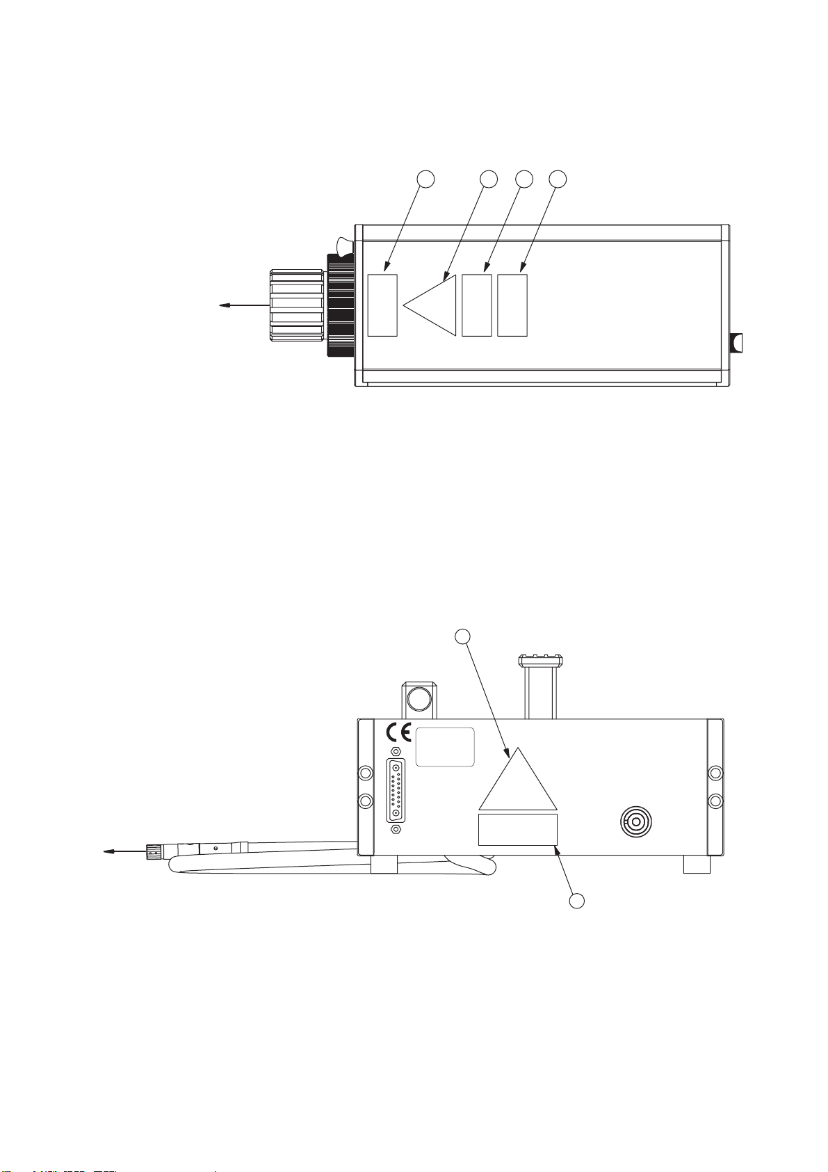
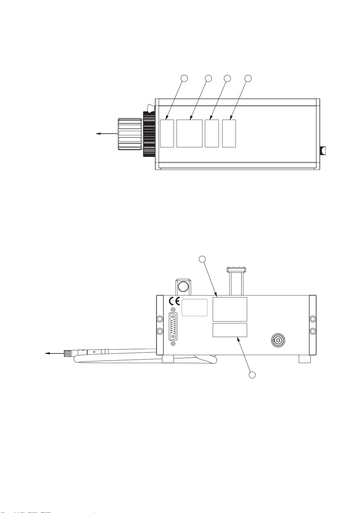
5.2 Beam Shutter and Emission Indicator..................................................................................5-1
5.3 Signal Level Display ............................................................................................................5-2
5.4 Focusing the Laser Beam....................................................................................................5-2
5.5 Exchanging the Front Lens..................................................................................................5-4
5.6 Making Single Point Measurements with the Sensor Head OFV-512 ...................................5-5
5.7 Fixing the Focus (only OFV-353) .........................................................................................5-5
5.8 Transport Safety Mechanism (only OFV-511/-512)...............................................................5-6
5.9 Operating the Vibrometer via the Display of the Controller...................................................5-7
5.9.1 Operating Philosophy.................................................................................................5-7
5.9.2 Organization of the Menus.........................................................................................5-8
5.9.3 The Individual Menus.................................................................................................5-9
5.10 Setting Measurement Ranges and Filters ........................................................................5-11
5.11 Displaying the Configuration of the Controller ..................................................................5-11
5.12 Configuring the Interfaces................................................................................................5-11
6 Fault Diagnosis 6-1
6.1 General Tests ......................................................................................................................6-1
6.2 No Laser Beam....................................................................................................................6-2
6.3 No Measurement Signal ......................................................................................................6-3
6.4 Checklist for Fault Diagnosis ...............................................................................................6-5
6.4.1 Controller OFV-3001 with the Sensor Head OFV-303/-353 ........................................6-5
6.4.2 Controller OFV-3001 with the Sensor Head OFV-511/-512.........................................6-6
7 Technical Specifications 7-1
7.1 Controller OFV-3001............................................................................................................7-1
7.1.1 General Data .............................................................................................................7-1
7.1.2 Interfaces...................................................................................................................7-1
7.1.3 Low Pass Filter..........................................................................................................7-2
7.1.4 Signal Voltage Output VELOCITY OUTPUT...............................................................7-2
7.1.5 Signal Voltage Output DISPLACEMENT OUTPUT (optional) .....................................7-5
7.2 Sensor Head OFV-303/-353 ................................................................................................7-6
7.2.1 General Data .............................................................................................................7-6
7.2.2 Optics........................................................................................................................7-6
7.3 Sensor Head OFV-511/-512.................................................................................................7-8
7.3.1 General Data .............................................................................................................7-8
7.3.2 Optics........................................................................................................................7-8
Appendix A: Optional Accessories for the Sensor Head OFV-303/-353
Appendix B: Optional Accessories for the Sensor Head OFV-511/-512
Appendix C: Basics of the Measurement Procedure
Appendix D: Functional Description of the Controller
Appendix E: Interface Operation RS-232 and IEEE-488/GPIB

1-1
1 Safety Information
1.1 Laser Safety
The light source of the vibrometer is a helium neon laser. It is important to
understand that laser light has different properties than ordinary light sources.
Laser radiation is generally extremely intense due to the beam's low
divergence and great care should be taken when handling laser instruments
that the direct or reflected beam does not enter the eye. To ensure this, the
following precautions have been taken:
•
In general, Polytec equipment complies with the standards
EN 60825-1
(DIN VDE 0837) and
CFR 1040.10
(US).
•
The optical output of the laser is less than 1mW for the sensor heads
OFV-303/-353
and
OFV-511
providing the equipment is used in the
manner for which it was intended. This means that the vibrometer
conforms with
laser class 2 (II)
and is generally very safe. Even when
optimally focused, the laser radiation is not intense enough to harm the
skin.
•
The optical output of the laser is less than 5mW (
<
1mW per fibre) for the
sensor head
OFV-512
providing the equipment is used in the manner for
which it was intended. This means that the vibrometer conforms with
laser class 3R
(IIIa)
and is generally very safe. Even when optimally
focused, the laser radiation is not intense enough to harm the skin.
•
The sensor head has been equipped with a
beam shutter
which can be
used to block the laser beam during the warm-up phase or when the
vibrometer is not in use, although switched on.
•
The
emission indicator
on the sensor head indicates the activity of the
laser and thus potential harm caused by emitted laser beams.
•
The beam shutter is always
less then 2m away
from the aperture of the
laser beam. Special editions of the fiber optical sensor heads with fiber
lengths of 3m are fitted with an additional emission indicator which is
integrated in the fibers.
•
The laser is switched on via a
key switch
on the controller. The key can
only be removed when the controller is switched off.
•
It is
not necessary to open
the housing of the sensor head when using
the vibrometer as intended. Opening the housing will invalidate the
warranty.
Please pay attention
to the following
safety precautions
when using the
vibrometer:
•
Never look directly into the laser beam with the naked eye or with the aid
of mirrors or optical instruments!
•
Only switch the beam shutter to the ON position when you are making
measurements!
•
To position the sensor head, switch the beam shutter to the OFF position.
Only when the sensor head is roughly in place and has been fixed in a
stable position, switch the beam shutter to ON.
•
Do not use any reflective tools, watches etc. when you are working in the
path of the laser beam!

1-2
1 Safety Information
1.2 Laser Warning Labels
1.2.1 EC Countries
Warning
labels
The laser warning labels for the sensor heads in EC countries are shown in
figure 1.1. Label
2
,
3
and
4
are affixed or enclosed in the language of the
customer’s country. Their position on the sensor head OFV-303/-353 is shown
in figure 1.2 and on the sensor head OFV-511 resp. OFV-512 in figure 1.3.
Laser class 2 for
OFV-303/-353 and OFV-511 Laser class 3R for
OFV-512
Figure 1.1: Laser warning labels for the vibrometer in EC countries
1
2
3
4

1-3
1 Safety Information
Position
The position of the laser warning labels in EC countries on the sensor head
OFV-303/-353 is shown in figure 1.2.
The position of the laser warning labels in EC countries on the sensor head
OFV-511 resp. OFV-512 is shown in figure 1.3.
For the sensor head OFV-511, label
3
is affixed inside.
For the sensor head OFV-512, label
4
is affixed inside and label
3
is enclosed
with the sensor head as it is not possible to affix it on the mini sensor due to
its size. Please affix this label clearly visible near the mounted mini sensor or
fiber head.
Figure 1.2: Position of the laser warning labels on the sensor head OFV-303/-353 in EC
countries
1
2 4
B e a m
3
Figure 1.3: Position of the laser warning labels on the sensor head OFV-511/-512 in EC countries
S I G N A L
P R O C E S S O R
A C H T U N G !
B i t t e v o r d e m T r a n s p o r t
d i e T r a n s p o r t s i c h e r n g b e t ä t i g e n
C A U T I O N !
P l e a s e s e c r e t r a n s p o r t m e c h a n i s m
b e f o r e s h i p m e n t
M E A S U R E M E N T T R A N S P O R T
B e a m
1
2

1-4
1 Safety Information
1.3 Laser Warning Labels
1.3.1 Non-EC Countries
Warning labels
The laser warning labels for the sensor heads in non-EC countries are shown
in figure 1.4. Their position on the sensor head OFV-303/-353 is shown in
figure 1.5 and on the sensor head OFV-511 resp. OFV-512 in figure 1.6.
Laser class II for
OFV-303/-353 and OFV-511
Laser class IIIa for
OFV-512
Figure 1.4: Laser warning
labels for the vibrometer in non-EC
countries

1-5
1 Safety Information
Position
The position of the laser warning labels in non-EC countries on the sensor
head OFV-303/-353 is shown in figure 1.5.
The position of the laser warning labels in non-EC countries on the sensor
head OFV-511 resp. OFV-512 is shown in figure 1.6.
Label
4
is affixed inside. Label
3
is enclosed with the sensor head as it is not
possible to affix it on the mini sensor due to its size. Please affix this label
clearly visible near the mounted mini sensor or fiber head.
Figure 1.5: Position of the laser warning labels on the sensor head OFV-303/-353 in non-EC
countries
1 4 2
3
B e a m
Figure 1.6: Position of the laser warning labels on the sensor ead OFV-511/-512 in non-EC countries
S I G N A L
P R O C E S S O R
A C H T U N G !
B i t t e v o r d e m T r a n s p o r t
d i e T r a n s p o r t s i c h e r n g b e t ä t i g e n
C A U T I O N !
P l e a s e s e c r e t r a n s p o r t m e c h a n i s m
b e f o r e s h i p m e n t
M E A S U R E M E N T T R A N S P O R T
B e a m
1
2

1-6
1 Safety Information
1.4 Electrical Safety
The vibrometer complies with the electrical safety class I. Electrical shock
protection is achieved by a fully metallic housing connected to protective
ground. Please pay attention to the following safety precautions when using
the vibrometer:
•
The vibrometer should only be connected via a three pin mains cable to
an AC mains supply 50/60Hz with a grounded protective conductor with a
nominal voltage which corresponds to the voltage set on the voltage
selector.
•
Defective mains fuses may only be replaced by fuses of the same kind
with their rating given on the back of the controller.
•
None of the equipment may be used with open housing. As a general rule,
before removing parts of the housing, the mains cable has to be
unplugged.
•
Air inlets and outlets must always be kept uncovered to ensure effective
cooling. If the cooling fan stops working, the vibrometer is to be switched
off immediately.

2-1
2 Introduction
2 Introduction
2.1 System Overview
Polytec vibrometers are instruments for non-contact measurement of surface
vibrations based on laser interferometry. The vibrometer consists of the
controller OFV-3001 and the sensor head OFV-303/-353 or OFV-511/-512.
The signal paths in the vibrometer are shown schematically in figure 2.1.
The beam of a helium neon laser is focused on the object under investigation,
scattered back from there and coupled back into the interferometer in the
sensor head. The interferometer compares the phase
ϕ
mod
and frequency f
mod
of the object beam with those of the internal reference beam
ϕ
0
and f
0
. The
frequency difference is proportional to the instantaneous velocity and the
phase difference is proportional to the instantaneous position of the object.
In the controller, the resulting signal is decoded using the velocity decoder
and optionally the displacement decoder. Two voltage signals are generated
which are respectively proportional to the instantaneous VELOCITY and to
the instantaneous position (DISPLACEMENT) of the object. Both signals are
available at the front of the controller as an analog voltage and can be
processed further externally. Additional functions such as filters and signal
level display raise the level of comfort for the vibrometer user. The settings of
the vibrometer are selected via the display of the controller or via PC
interfaces.
To display and analyze measurement results on a workstation, the Polytec
Vibrometer Software (VibSoft) is available optionally. The software is
described in a separate manual.
Figure 2.1: Signals in the vibrometer
S e n s o r h e a d
f0
j0
fm o d
j
m o d
F r e q u e n c y
P h a s e
Df
V e l o c i t y
d e c o d e r
V
D i s p l a c e m e n t
d e c o d e r ( o p t i o n a l
D j
V
v ( t )
x ( t )
O b j e c t
x ( t
v ( t = d x / d t

2-2
2 Introduction
2.2 Component Summary
Polytec assembles the vibrometer on the modular principle thus permitting a
user-specific configuration. The combination of the controller OFV-3001 with
the most useful decoders as well as a suitable sensor head provide the
solution to a multitude of measurement tasks. Thus a manageable number of
components cover a wide range of applications. A summary of the
components is shown in figure 2.2.
The modularity is achieved initially through strict separation of optics and
electronics. Every decoder can be combined with every sensor head.
The controller is equipped with one of the two available velocity decoders as
standard. A maximum of two velocity decoders can be installed. The velocity
decoders are described in section D.4.1.
As an option, the controller can be fitted with one of the four available
displacement decoders as well as be supplemented by a PC-based
displacement decoder (refer to section D.5.2).
The various standard and fiber optical sensor heads comply with the different
requirements of the vibrometer’s optics. For every sensor head a selection of
lenses covers a wide range of stand-off distances.
Figure 2.2: Compatibility of the controller OFV-3001 with sensor heads and decoders
O F V - 3 0 0 1
O V D - 1 0
O V D - 2 0
O V D - 3 0
O V D - 4 0
O V D - 0 1
O V D - 0 2
O F V - 3 0 3
O F V - 3 5 3
O F V - 5 1 1
O F V - 5 1 2
F i b e r o p t i c a l
s e n s o r h e a d s
S t a n d a r d
s e n s o r h e a d s
V e l o c i t y d e c o d e r s D i s p l a c e m e n t d e c o d e r s

3-1
3 First Steps
3 First Steps
3.1 Operating and Maintenance Requirements
Operating
environment
The vibrometer can be operated in dry rooms under normal climate conditions
(refer to chapter 7). In particular the optical components in the sensor head
are sensitive to moisture, high temperatures, jolting and dirt. When the
vibrometer is taken into operation after being stored somewhere cool, a
sufficient acclimatization period should be allowed for before switching it on.
Avoid condensation on the optical components caused by a rapid change in
temperature.
Mains
connection
Before taking the vibrometer into operation, please ensure that the supply
voltage set with the voltage selector corresponds with the local mains voltage.
Only replace defective fuses by fuses of the same kind and equal rating.
Warming-up
The helium neon laser in the sensor head requires a certain period of time to
reach optimum stability. The vibrometer should thus be switched on 20
minutes before the first measurements are made to ensure that it is in thermal
equilibrium with the surroundings.
Assembly
The sensor head OFV-303 should not be positioned provisionally but
mounted properly on a stable tripod using the threads provided.
Transport
The sensor head OFV-511/-512 is equipped with a transport safety
mechanism which always has to be activated before moving the sensor head
(refer to section 5.8).
Connecting
cables
As a general rule the vibrometer must not be switched on until all cables are
connected. Make sure that all jacks are connected properly and firmly. Protect
the cables from mechanical damage and from high temperatures.
Cleaning
The housing surfaces of the instrument can be cleaned with mild detergent
solutions. Organic solvents must not be used.
Optical
components
Handle all optical components with great care. Dirt may only be removed very
carefully with a soft, dry cloth, an optics brush and bellow.
Cooling
It is very important to ensure that there is sufficient air circulation to keep the
controller and the sensor head cool. The air vents of the sensor head must
never be covered up and the back panel of the controller must be at least
50mm away from the wall.
Opening up
the equipment
Opening up of the equipment without authorization is not necessary for its
operation and will invalidate the warranty.

3-2
3 First Steps
3.2 Unpacking and Inspection
The vibrometer consists of the following components:
•
controller OFV-3001
•
sensor head OFV-303/-353 or OFV-511/-512
•
connecting cable from the controller to the sensor head (length 5m)
•
earthed mains cable
Please pay attention to the following steps when unpacking:
1. After unpacking, check all components for external damage (scratches,
loose screws, damaged lens etc.).
2. Check the packaging for signs of unsuitable handling during transport.
3. In the case of a wrong delivery, damage or missing parts, inform your local
Polytec representative immediately and give them the serial number of the
sensor head and the controller. The identification labels can be found on
the back of the instruments and also on the inside cover of this manual.
4. Carefully retain the original packaging in case you have to return the
instrument.
5. Install the vibrometer and carry out a first functional test as described in
section 3.4.1 (sensor head OFV-303/-353) or section 3.4.2 (sensor head
OFV-511/-512).
Caution!
Protect the unpacked sensor head from hard jolts as these can lead to misalignment of the
interferometer!
Caution!
Handle the front lens of the sensor head with great care! Dirt may only be removed very
carefully with a soft, dry cloth, an optics brush and bellow!

3-3
3 First Steps
3.3 Control Elements of the Vibrometer
3.3.1 Controller
The front panel of the controller is shown in figure 3.1.
1
POWER
- L
ED
The L
ED
lights up when the key switch on the controller is turned to
position I and indicates that the controller is ready to operate.
2
Mains Switch
This key switch disconnects the vibrometer from the mains (position O)
and is used to switch it off in the case of danger.
3
Liquid Crystal Display (LCD)
with background lighting
This display shows the configuration and the settings of the vibrometer.
The organization of the display and how to use it to operate the
vibrometer are described in detail in section 5.9.
4
FUNCTION
- keys
Using these keys the cursor is moved vertically up (
↑)
or down (
↓
) on the
display. This is used to select parameters or to change between menus
(refer to section 5.9.1).
5
SETTING
- keys
Using these keys the settings are changed to higher (
+
) or lower (
−
)
values (refer to section 5.9.1).
Figure 3.1: Front view of the controller
O
P O W E R
O F V 3 0 0 1
V I B R O M E T E R C O N T R O L L E R
3
2 1 3 1 2 1 1 1 0
LLO R E M O T E R E S E T
F U N C T I O N S E T T I N G
4 5 6 7
+
-
O V E R O U T P U T
V E L O C I T Y
D I S P L A C E M E N T
C L E A R
O U T P U T
9 8
I
1
Caution!
Always connect the connecting cable to the sensor head before switching the controller
on!

3-4
3 First Steps
6
OVER
- indicator for the velocity
The L
ED
lights up when the output voltage exceeds either of the positive
or negative full scale of the velocity measurement range. If it lights up
permanently, the next highest velocity measurement range must be
selected (refer also to section 4.2.2).
7
Analog
voltage
OUTPUT
for the
VELOCITY
signal (BNC jack)
The voltage at this output is proportional to the instantaneous vibration
velocity of the object under investigation. The voltage is positive when the
object is moving towards the sensor head.
8
CLEAR
- input for the displacement decoder (BNC jack)
This input is only active, if a displacement decoder is installed. It allows
synchronized resetting of the displacement decoder. This can be used to
remove a DC component which is superimposed on a periodic vibration
(refer to section 4.2.3).
9
Analog voltage
OUTPUT
for the
DISPLACEMENT
signal (BNC jack)
This output is only active, if a displacement decoder is installed. The
voltage at this jack is proportional to the instantaneous displacement of
the object to be measured. The voltage increases when the object is
moving towards the sensor head.
10
CLEAR
- key for the displacement decoder
This key is only active, if a displacement decoder is installed. Using this
key the displacement decoder can be reset manually (refer to
section 4.2.3).
11
RESET
- key
Using this key the controller processor can be reset. The setting of the
controller is subsequently the same as it was straight after switching on
the mains.
12
REMOTE
- L
ED
The L
ED
is lit when the controller is being operated remotely via one of the
PC interfaces (refer to appendix E). Manual operation with the keys
↑
,
↓
,
+, - is also still possible (as oppose to the status Local Lock Out).
13
LLO
- L
ED
This L
ED
is lit when the status
L
ocal
L
ock
O
ut has been activated via one
of the PC interfaces (refer to appendix E). The keys
↑
,
↓
,
+
,
−
are then
deactivated and the controller can only be operated via the PC interfaces.

3-5
3 First Steps
The back panel of the controller is shown in figure 3.2.
1
INTERFEROMETER
- connector (Sub-D jack)
Jack for the connecting cable to the sensor head
2
Mains connection combination
Socket for standard power cord with built-in fuses and mains voltage
selector (refer to section 3.1)
3
EXT
ernal
DEC
oder - interface
Interface for an external PC-based displacement decoder (refer to
section D.5.2)
4
REMOTE FOCUS
- interface
Interface for the optional hand terminal OFV-310 to focus the laser beam
(refer to section A.1)
5
SIGNAL
- output (BNC jack)
The DC voltage at this output is proportional to the logarithm of the optical
signal level.
6
GPIB/IEEE-488
- interface
Jack for the IEEE-488/GPIB cable (refer to appendix E)
Figure 3.2: Rear view of the controller
I N T E R F E R O M E T E R
R S 2 3 2
E X T . D E C .
S I G N A L R E M O T E F O C U S
G P I B / I E E E - 4 8 8
6 7 8 1 2
5 4 3
Warning!
Always disconnect from the mains before checking the fuses!
Caution!
Always check the setting of the voltage selector as well as the fuses before installing the
controller!

3-7
3 First Steps
3.3.2 Sensor Head OFV-303
The back panel and the front panel of the sensor head OFV-303 are shown in
figure 3.3.
1
Beam shutter
In position OFF the laser beam is blocked.
2
CONTROLLER
- connector (Sub-D jack)
Jack for the connecting cable to the controller
3
Signal level display
The length of the bar is a measure of the amount of light scattered back
from the surface of the object.
4
LASER
- L
ED
The L
ED
lights up when the laser is switched on (key switch on the
controller in position I) i.e. even if the beam shutter is closed (refer to
section 5.2).
5
Switch
AUTO/MAN
This knob is used to switch between remote-controlled and manual
focusing (refer to section 5.4).
6
Front lens
Exchange of the front lens is described in section 5.5.
7
Focusing ring
Focusing ring for manual focusing of the laser beam (refer to section 5.4)
Figure 3.3: Rear view and front view of the sensor head OFV-303
C O N T R O L L E R
O F F
O N
E M I S S I O N
L A S E R
S
I
G
N
A
L
123567
4
A U T O M A N
&
Warning!
Only switch the beam shutter to position ON when you are making measurements!

3-8
3 First Steps
3.3.3 Sensor Head OFV-353
The back panel and the front panel of the sensor head OFV-353 are shown in
figure 3.4.
1
Beam shutter
In position OFF the laser beam is blocked.
2
CONTROLLER
- connector (Sub-D jack)
Jack for the connecting cable to the controller
3
Signal level display
The length of the bar is a measure of the amount of light scattered back
from the surface of the object.
4
LASER
- L
ED
The L
ED
lights up when the laser is switched on (key switch on the
controller in position I) i.e. even if the beam shutter is closed (refer to
section 5.2).
5
Switch
BRAKE ON/OFF
This knob is used to fix the focus (refer to section 5.7).
6
Front lens
Exchange of the front lens is described in section 5.5.
7
Focusing ring
Focusing ring for focusing of the laser beam (refer to section 5.4)
Figure 3.4: Rear view and front view of the sensor head OFV-353
O N O F F
BRAKE
&
567
3
2
1
4
E M I S S I O N
O F F
O N
C O N T R O L L E R
L A S E R
S
I
G
N
A
L
Warning!
Only switch the beam shutter to position ON when you are making measurements!
Other manuals for OFV-3001
1
This manual suits for next models
4
Table of contents
Other Polytec Measuring Instrument manuals

Polytec
Polytec MSA-600 User manual

Polytec
Polytec PSV-500-3D User manual

Polytec
Polytec PSV-500 User manual

Polytec
Polytec OFV-3001 User manual

Polytec
Polytec PDV-100 User manual

Polytec
Polytec TMS-500 TopMap Pro.Surf User manual

Polytec
Polytec PSV 300 User manual

Polytec
Polytec TMS-350 TopMap In.Line User manual
Popular Measuring Instrument manuals by other brands

Sper scientific
Sper scientific 801038 instruction manual

Minipa
Minipa MFA-840 instruction manual

PCE Health and Fitness
PCE Health and Fitness PCE-TG 75 user manual

Triner Scale
Triner Scale TS-700 MS user guide

Rigol
Rigol DS1000E Series, DS1000D Series Programming guide

Badger Basket
Badger Basket 3000+ manual