Operation
Normal Operation and Use
1) Locate unit on a solid, dry working surface, or mount in a 19” equipment rack.
2) Select the operating voltage range (115VAC or 230VAC) by setting the Line Select Switch, located on the rear panel,
to the appropriate setting. Please refer to “Setting the AC Line Voltage and Installing Fuses”.
3) Connect the line cord provided with the unit (US units only) to the receptacle on the rear panel, then connect the line
cord to a properly grounded power source.
4) If you wish to use the remote interlock feature connect a suitable interlock switch to the Interlock connector on the rear
panel (refer to “Making the Safety Interlock Connection” in this manual). Otherwise use the shorting device provided
with the unit. In all cases however, the Interlock connector must have a short circuit across its terminals in order to
enable the lasers.
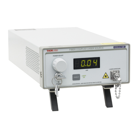
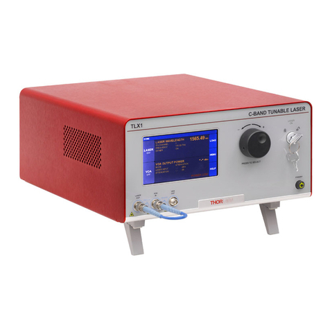
5) Turn the unit On by turning the key lock power switch on the front panel in a clockwise direction. The green indicator
below the switch will turn on.
6) Connect single mode FC/PC terminated optical fibers to each of the output apertures. This will require unscrewing
the aperture caps. NOTE: For best results always clean the ferrules of the mating fiber connector before inserting it
into the aperture. Keep all unused apertures capped.
Enabling the Outputs
Each output channel can be turned on in one of two sequences:
a) Press the Master Enable switch on the front panel, then press the individual output controls to enable selected
channels…
b) Press the individual output controls of up to four channels, then press the Master Enable switch to cause all
selected channels to turn on at the same time.
In either case, both the Master Enable indicator and the individual channel indicator must be ON, indicating that
particular channel is outputting light.
Note: The turn on rise-time will vary depending on whether method “a” or method “b” is used, with method “a”
providing the faster rise-time.
Adjusting the Output Power of each Channel
The Output power of each channel can be controlled by one of a number of methods:
a) Turning the front panel Power Adjust knob clockwise will cause the output of all four channels to increase
simultaneously.
b) Applying a 0 – 5 VDC signal to the respective Modulation Input connector on the rear panel will allow controlling
each channel individually. 0 volts corresponding to 0 power and 5 VDC corresponding to full power.
c) Applying a 0 – 5 VAC sinusoidal signal to the respective Modulation Input connector on the rear panel will allow
modulating each channel individually at frequencies up to 30KHz*.
d) Using the front panel Power Adjust knob in conjunction with a Modulation Input (DC to 30KHz) will add a DC
offset to the Modulation signal. However, no combination of the two controls can cause the power to exceed the
maximum for the unit.
6374-D02 Rev. D 8/15/05 Page 5 of 9
