Fluke Biomedical ESA612 User manual

FBC-0031
March 2009 | Rev. 3, 3/22
© 2009-2022 Fluke Corporation. All rights reserved. Specifications are subject to change without notice.
All product names are trademarks of their respective companies.
ESA612
Electrical Safety Analyzer
User Manual

Warranty and Product Support
Fluke Biomedical warrants this instrument against defects in materials and workmanship for one year from the date of
original purchase OR two years if at the end of your first year you send the instrument to a Fluke Biomedical service center
for calibration. You will be charged our customary fee for such calibration. During the warranty period, we will repair or at our
option replace, at no charge, a product that proves to be defective, provided you return the product, shipping prepaid, to
Fluke Biomedical. This warranty covers the original purchaser only and is not transferable. The warranty does not apply if the
product has been damaged by accident or misuse or has been serviced or modified by anyone other than an authorized
Fluke Biomedical service facility. NO OTHER WARRANTIES, SUCH AS FITNESS FOR A PARTICULAR PURPOSE, ARE
EXPRESSED OR IMPLIED. FLUKE SHALL NOT BE LIABLE FOR ANY SPECIAL, INDIRECT, INCIDENTAL OR
CONSEQUENTIAL DAMAGES OR LOSSES, INCLUDING LOSS OF DATA, ARISING FROM ANY CAUSE OR THEORY.
This warranty covers only serialized products and their accessory items that bear a distinct serial number tag. Recalibration
of instruments is not covered under the warranty.
This warranty gives you specific legal rights and you may also have other rights that vary in different jurisdictions. Since
some jurisdictions do not allow the exclusion or limitation of an implied warranty or of incidental or consequential damages,
this limitation of liability may not apply to you. If any provision of this warranty is held invalid or unenforceable by a court or
other decision-maker of competent jurisdiction, such holding will not affect the validity or enforceability of any other provision.
7/07

Notices
All Rights Reserved
Copyright 2008-2022, Fluke Biomedical. No part of this publication may be reproduced, transmitted, transcribed, stored in a retrieval
system, or translated into any language without the written permission of Fluke Biomedical.
Copyright Release
Fluke Biomedical agrees to a limited copyright release that allows you to reproduce manuals and other printed materials for use in service
training programs and other technical publications. If you would like other reproductions or distributions, submit a written request to Fluke
Biomedical.
Unpacking and Inspection
Follow standard receiving practices upon receipt of the instrument. Check the shipping carton for damage. If damage is found, stop unpacking
the instrument. Notify the carrier and ask for an agent to be present while the instrument is unpacked. There are no special unpacking
instructions, but be careful not to damage the instrument when unpacking it. Inspect the instrument for physical damage such as bent or
broken parts, dents, or scratches.
Technical Support
For application support or answers to technical questions, either email techservic[email protected] or call 1-800- 850-4608 or 1-425-
446-6945.
Claims
Our routine method of shipment is via common carrier, FOB origin. Upon delivery, if physical damage is found, retain all packing materials in
their original condition and contact the carrier immediately to file a claim. If the instrument is delivered in good physical condition but does not
operate within specifications, or if there are any other problems not caused by shipping damage, please contact Fluke Biomedical or your local
sales representative.

Standard Terms and Conditions
Refunds and Credits
Please note that only serialized products and their accessory items (i.e., products and items bearing a distinct serial number tag) are
eligible for partial refund and/or credit. Non-serialized parts and accessory items (e.g., cables, carrying cases, auxiliary modules,
etc.) are not eligible for return or refund. Only products returned within 90 days from the date of original purchase are eligible for
refund/credit. In order to receive a partial refund/credit of a product purchase price on a serialized product, the product must not have been
damaged by the customer or by the carrier chosen by the customer to return the goods, and the product must be returned complete (meaning
with all manuals, cables, accessories, etc.) and in “as new” and resalable condition. Products not returned within 90 days of purchase, or
products which are not in “as new” and resalable condition, are not eligible for credit return and will be returned to the customer. The Return
Procedure (see below) must be followed to assure prompt refund/credit.
Restocking Charges
Products returned within 30 days of original purchase are subject to a minimum restocking fee of 15 %. Products returned in excess
of 30 days after purchase, but prior to 90 days, are subject to a minimum restocking fee of 20 %. Additional charges for damage and/or
missing parts and accessories will be applied to all returns.
Return Procedure
All items being returned (including all warranty-claim shipments) must be sent freight-prepaid to our factory location. When you return an
instrument to Fluke Biomedical, we recommend using United Parcel Service, Federal Express, or Air Parcel Post. We also recommend that
you insure your shipment for its actual replacement cost. Fluke Biomedical will not be responsible for lost shipments or instruments that are
received in damaged condition due to improper packaging or handling.
Use the original carton and packaging material for shipment. If they are not available, we recommend the following guide for repackaging:
Use a double–walled carton of sufficient strength for the weight being shipped.
Use heavy paper or cardboard to protect all instrument surfaces. Use nonabrasive material around all projecting parts.
Use at least four inches of tightly packed, industry-approved, shock-absorbent material around the instrument.

Returns for partial refund/credit:
Every product returned for refund/credit must be accompanied by a Return Material Authorization (RMA) number, obtained from our Order
Entry Group at 1-800-648-7952 or 1-425-446-6945.
Repair and calibration:
To find the nearest service center, go to www.flukebiomedical.com/service.
For customers based in the U.S.A., please contact Fluke Electronics at [email protected], or call 1-833-296-9420.
All other customers, please go to www.flukebiomedical.com/service to find the nearest service center.
Certification
This instrument was thoroughly tested and inspected. It was found to meet Fluke Biomedical’s manufacturing specifications when it was
shipped from the factory. Calibration measurements are traceable to the National Institute of Standards and Technology (NIST). Devices for
which there are no NIST calibration standards are measured against in-house performance standards using accepted test procedures.
WARNING
Unauthorized user modifications or application beyond the published specifications may result in electrical shock hazards or improper
operation. Fluke Biomedical will not be responsible for any injuries sustained due to unauthorized equipment modifications.
Restrictions and Liabilities
Information in this document is subject to change and does not represent a commitment by Fluke Biomedical. Changes made to the
information in this document will be incorporated in new editions of the publication. No responsibility is assumed by Fluke Biomedical
for the use or reliability of software or equipment that is not supplied by Fluke Biomedical, or by its affiliated dealers.
Manufacturing Location
The ESA612 Electrical Safety Analyzer is manufactured at Fluke Biomedical, 6920 Seaway Blvd., Everett, WA, U.S.A.


i
Table of Contents
Title Page
Introduction ....................................................................................................................1
Safety Information ..........................................................................................................3
Intended Use ..................................................................................................................4
Unpacking the Analyzer .................................................................................................5
Instrument Familiarization ..............................................................................................6
How to Hold the Product ................................................................................................10
Connecting to Line Power ..............................................................................................10
Connecting a DUT to the Analyzer .................................................................................11
Turning the Analyzer On ................................................................................................11
Accessing the Analyzer’s Functions ...............................................................................13
Setting Up the Analyzer..................................................................................................14
Setting the GFCI Limit ...............................................................................................14
Setting the Display Contrast ......................................................................................15
Setting up the Beeper................................................................................................16

ESA612
Users Manual
ii
Viewing Instrument Information................................................................................. 16
Viewing Memory ....................................................................................................... 16
Setting the GFCI Limit............................................................................................... 16
Performing Electrical Safety Tests................................................................................. 17
Setting the Test Standard ......................................................................................... 17
Performing Mains Voltage Testing ............................................................................ 17
Performing a Ground Wire (Protective Earth) Resistance Test................................. 18
Performing an Insulation Resistance Test ................................................................ 23
Performing a Current Consumption Test .................................................................. 29
Performing Leakage Current Tests ........................................................................... 29
Measuring Earth Leakage Current ....................................................................... 30
Performing a Chassis (Enclosure) Leakage Test ................................................. 33
Performing a Lead-to-Ground (Patient) Leakage Test ......................................... 35
Performing Lead-to-Lead (Patient Auxiliary) Leakage Tests................................ 37
Performing a Lead Isolation (Mains on Applied Part) Leakage Test ......................... 39
Performing an Alternative Equipment Leakage Test................................................. 42
Performing an Alternative Applied Part Leakage Test .............................................. 43
Performing a Direct Equipment Leakage Test .......................................................... 45
Performing a Direct Applied Part Leakage Test ........................................................ 48
Performing a Differential Leakage Current Test........................................................ 51
Using the 1-to-10 Adapter.............................................................................................. 53
Making Point-To-Point Measurements........................................................................... 57
Measuring Voltage .................................................................................................... 57
Measuring Resistance .............................................................................................. 57
Measuring Current .................................................................................................... 58
Simulating ECG Waveforms .......................................................................................... 58
Using Memory ............................................................................................................... 61
Storing Data into Memory ......................................................................................... 61
Viewing Memory Data............................................................................................... 62

Contents (continued)
iii
Deleting Data from Memory.......................................................................................63
Controlling the Analyzer Remotely .................................................................................63
Maintenance...................................................................................................................64
Testing and Replacing the Fuses ...................................................................................64
Cleaning the Analyzer ....................................................................................................66
Replaceable Parts ..........................................................................................................67
Accessories....................................................................................................................69
Specifications .................................................................................................................70
Detailed Specifications ...................................................................................................71

ESA612
Users Manual
iv

v
List of Tables
Table Title Page
1. Symbols................................................................................................................................. 2
2. Top-Panel Controls and Connections.................................................................................... 6
3. Side and Top-Panel Connections.......................................................................................... 9
4. Schematic Abbreviations ....................................................................................................... 21
5. Test Names Based on Selected Standard............................................................................. 29
6. Replaceable Parts ................................................................................................................. 68
7. Accessories ........................................................................................................................... 70

ESA612
Users Manual
vi

vii
List of Figures
Figure Title Page
1. Front-Panel Controls and Connections ................................................................................. 6
2. Side and Top-Panel Connections.......................................................................................... 8
3. Product Handle...................................................................................................................... 10
4. Analyzer Ready for Operation ............................................................................................... 11
5. DUT Connections to the Analyzer ......................................................................................... 12
6. Leakage Current Menu.......................................................................................................... 13
7. Setup Menu ........................................................................................................................... 14
8. Mains Voltage Test Menu...................................................................................................... 17
9. DUT Ground Resistance Measurement................................................................................. 18
10. Ground Wire (Protective Earth) Resistance Measurement Connections............................... 20
11. Ground Wire (Protective Earth) Resistance Measurement Schematic .................................. 22
12. Insulation Resistance Measurement ..................................................................................... 23
13. Mains to Protective-Earth Insulation Resistance Test Schematic.......................................... 24
14. Applied Parts to Protective-Earth Insulation Test Schematic................................................. 25
15. Mains to Applied Parts Insulation Test Schematic................................................................. 26

ESA612
Users Manual
viii
16. Mains to Non-Earth Accessible Conductive Points Schematic ............................................. 27
17. Applied Parts to Non-Earth Conductive Points Schematic.................................................... 28
18. Leakage Current Main Menu ................................................................................................ 30
19. Earth Leakage Current Test Schematic ................................................................................ 32
20. Enclosure Leakage Current Test Schematic......................................................................... 34
21. Lead-to-Ground (Patient) Leakage Current Test Schematic................................................. 36
22. Applied Parts Connection Posts Display............................................................................... 37
23. Lead-to-Lead (Patient Auxiliary) Leakage Current Test Schematic ...................................... 39
24. Lead Isolation (Mains On Applied Parts) Leakage Test Schematic ...................................... 42
25. Alternative Equipment Leakage Current Test Schematic...................................................... 45
26. Alternative Applied Part Leakage Test Schematic ................................................................ 48
27. Direct Equipment Leakage Test Schematic .......................................................................... 50
28. Direct Applied Parts Leakage Current Test Schematic ......................................................... 51
29. Differential Leakage Current Test Schematic ....................................................................... 53
30. 1-to-10 Adapter Connections ................................................................................................ 55
31. ECG Lead Connection with 1-to-10 Adapter......................................................................... 57
32. Point-To-Point Function Menu .............................................................................................. 58
33. ECG Waveform Simulation Menu ......................................................................................... 59
34. ECG Monitor Connections .................................................................................................... 61
35. Test Record ID Entry Screen ................................................................................................ 63
36. Fuse Access ......................................................................................................................... 66

1
Electrical Safety Analyzer
Introduction
The Fluke Biomedical ESA612 Electrical Safety Analyzer
(hereafter the Analyzer) is a full-featured, compact,
portable analyzer, designed to verify the electrical safety
of medical devices. The Analyzer tests to domestic
(ANSI/AAMI ES1, NFPA 99) and international (IEC62353,
AN/NZS 3551, and parts of IEC 60601-1) electrical-safety
standards. The integrated ANSI/AAMI ES1 and
IEC60601-1 patient loads are easily selectable.
The Analyzer performs the following tests:
•Line (Mains) voltage
•Ground Wire (or Protective Earth) Resistance
•Equipment current
•Insulation resistance
•Ground (Earth) leakage
•Chassis (Enclosure) leakage
•Lead to Ground (Patient) and Lead to Lead (Patient
Auxiliary) leakage
•Lead isolation (Mains on applied parts leakage)
•Differential leakage
•Direct equipment leakage
•Direct applied part leakage
•Alternative equipment leakage
•Alternative applied part patient leakage
•Point to point leakage, voltage, and resistance
•ECG simulation and performance waveforms

ESA612
Users Manual
2
Table 1. Symbols
Symbol Description
Important information; refer to manual.
Hazardous voltage
� Consult user documentation
Conforms to European Union directives
This product complies with the WEEE Directive (2002/96/EC) marking requirements. The affixed label
indicates that you must not discard this electrical/electronic product in domestic household waste. Product
Category: With reference to the equipment types in the WEEE Directive Annex I, this product is classed as
category 9 "Monitoring and Control Instrumentation" product. Do not dispose of this product as unsorted
municipal waste. Go to Fluke’s website for recycling information.
CAT II
Measurement Category II is applicable to test and measuring circuits connected directly to utilization points
(socket outlets and similar points) of the low-voltage mains installation.
Accessible Functional Earth Terminal

Electrical Safety Analyzer
Safety Information
3
Safety Information
In this manual, a Warningidentifies hazardous conditions
and actions that could cause bodily harm or death. A
Caution identifies conditions and actions that could
damage the Analyzer, the equipment under test, or cause
permanent loss of data.
Warning
To avoid possible electrical shock or
personal injury, follow these guidelines:
•Use this Analyzer only in the manner
specified by the manufacturer or the
protection provided may be impaired.
•Read the Users Manual before operating
the Analyzer.
•Do not connect the Analyzer to a patient or
equipment connected to a patient. The
Analyzer is intended for equipment
evaluation only and should never be used
in diagnostics, treatment or in any other
capacity where the Analyzer would come
in contact with a patient.
•Do not use the product in wet or damp
locations, around explosive gases or dust.
•Inspect the Analyzer before using it. Do
not use the Analyzer if abnormal
conditions of any sort are noted (such as a
faulty display, broken case, etc.)
•Inspect the test leads for damaged
insulation or exposed metal. Check test
lead continuity. Replace damaged leads
before using the Analyzer.
•When testing, always be sure to keep your
fingers behind the safety barriers on the
test leads.
•Never open the Analyzer's case.
Dangerous voltages are present. There are
no user replaceable parts in the Analyzer.
•Have the Analyzer serviced only by
qualified personnel.

ESA612
Users Manual
4
•The Analyzer must be properly earthed.
Only use a supply socket that has a
protective earth contact. If there is any
doubt as to the effectiveness of the supply
socket earth, do not connect the Analyzer.
Do not use a two-conductor adapter or
extension cord; this will break the
protective ground connection.
•Do not use the 15-20 A adapter to power
devices rated in excess of 15 A. Doing so
may overload the installation.
•Use extreme caution when working with
voltages above 30 V.
•Use the proper terminals, functions and
ranges for the test being performed.
•Do not touch metal parts of the device
under test (DUT) during analysis. The DUT
should be considered an electrical shock
hazard when connected to the Analyzer as
some tests involve high voltages, high
currents, and/or the removal of DUT earth
bond.
Intended Use
The Product is an electronic signal source and
measurement device for verifying the electrical safety of
medical devices. The Product also provides ECG
simulation and performance waveforms to verify patient
monitors are performing within their operating
specifications.
The Product provides the following function categories:
•ECG Functions
•ECG-Performance Testing

Electrical Safety Analyzer
Unpacking the Analyzer
5
The intended user is a trained biomedical equipment
technician who performs periodic preventative
maintenance checks on patient monitors in service. Users
can be associated with hospitals, clinics, original
equipment manufacturers and independent service
companies that repair and service medical equipment.
The end user is an individual, trained in medical
instrumentation technology.
This Product is intended to be used in the laboratory
environment, outside of the patient care area, and is not
intended for use on patients, or to test devices while
connected to patients. This Product is not intended to be
used to calibrate medical equipment. It is intended for
over-the-counter use.
Unpacking the Analyzer
Carefully unpack all items from the box and check that
you have the following items:
•ESA612
•Getting Started Manual
•Users Manual CD
•Carrying case
•Power cord
•15 – 20 A Adapter (USA only)
•ESA USA Accessory Kit (USA, Australia, and Israel
only)
•ESA EUR Accessory Kit
•Ansur demo CD
•Null Post Adapter
•5-to-5 Banana to ECG Adapter (BJ2ECG)
•Transfer cable
ESA612
Users Manual
6
Instrument Familiarization
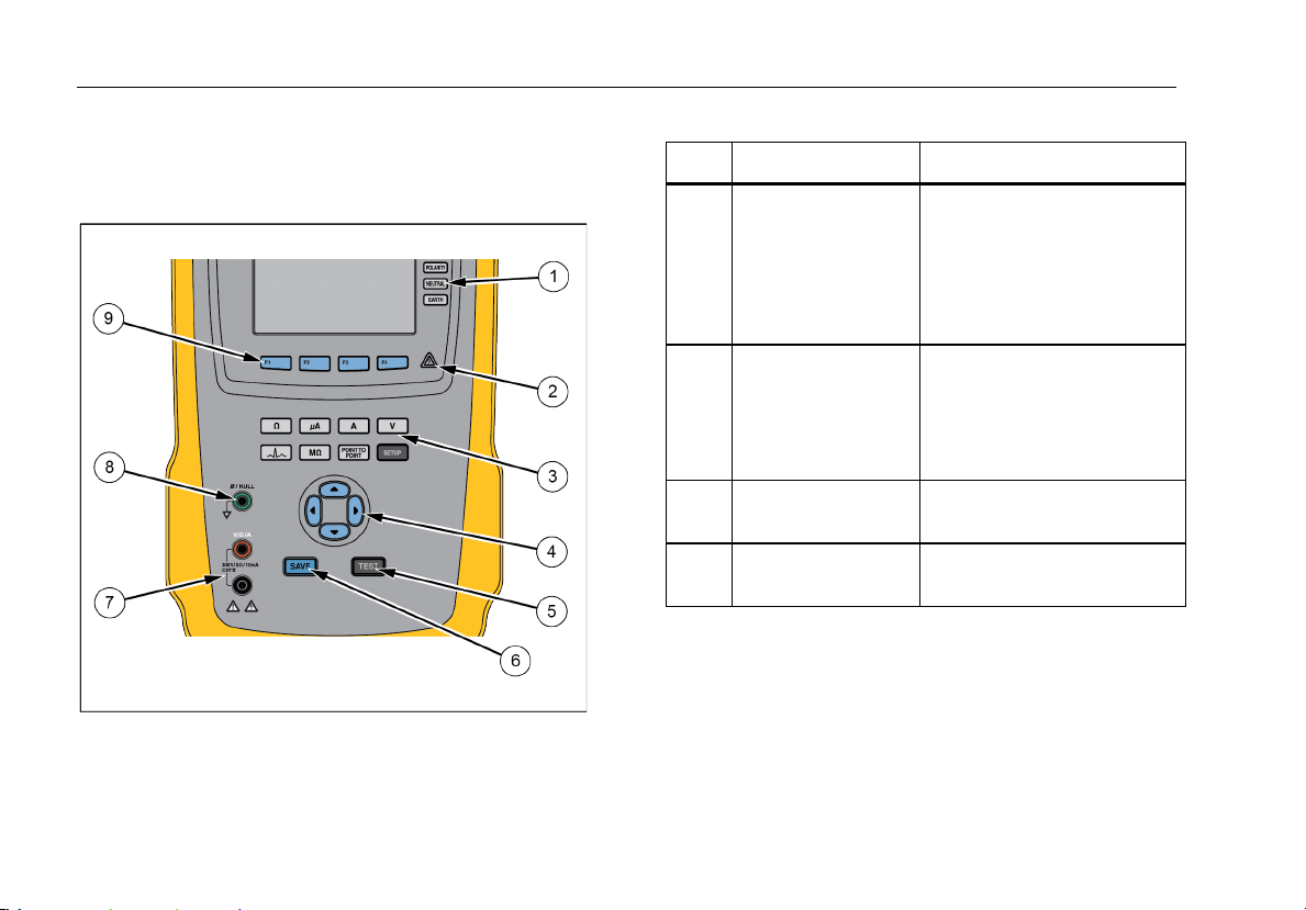
Figure 1 and Table 2 describes the front-panel controls
and connections of the Analyzer.
fis116.png
Figure 1. Front-Panel Controls and Connections
Table 2. Top-Panel Controls and Connections
Item Name Description
1
Equipment Outlet
Configuration
Buttons
Controls the configuration of
the equipment outlet. Opens
and closes the neutral and
ground connection and
reverses the polarity of the
neutral and hot connection.
2 High Voltage
Indicator
Indicates when high voltage
is applied to the
ECG/Applied Parts posts or
L1 and L2 of the Test
Receptacle.
3 Test Function
Buttons
Selects the various Analyzer
test functions.
4 Navigation Buttons Cursor control buttons for
navigating menus and lists.
Other manuals for ESA612
1
Table of contents
Other Fluke Biomedical Test Equipment manuals


