CryptOn EB30 User manual
EB30/EC30/630 Upgrade Page 1
Commercial Vehicle Roller Brake Tester.
EB30/EC30/630 Upgrade
OPERATING INSTRUCTIONS TES1343/A
July 2001

EB30/EC30/630 Upgrade Page 2
IMPORTANT
Every reasonable effort has been made to ensure that information within these Operating Instructions is correct
at the time of release, but Crypton cannot accept-responsibility for any errors that may occur.
The information in these Operating Instructions is subject to change without notice, and does not represent a
commitment on the part of Crypton.
Service & Warranty
The reliability of this equipment is fully supported by our service agent.
Please refer to the page at the end of this manual for full details.
Note:
Your attention is drawn to our Terms & Conditions of Sale, particularly paragraph 2. If a service engineer is
called out. under service warranty where, upon inspection and test the equipment is found to be in full working
order and no fault found, the user is liable to be charged the cost incurred for this call out. Before calling out
an engineer, ensure your equipment is faulty by checking its operation, particularly mains supply and fault
codes/self test if applicable.
WARNING:
Do not attempt to operate this equipment unless you have read and understood these
instructions.

EB30/EC30/630 Upgrade Page 3
Index:
Safety procedures for brake testing procedures 2
Description 3
Functions and Facilities 6
PC Brake Diagnostic Program 9
The Theory of Brake Testing 12
Preparing for a Brake Test 14
Automatic Test Procedure (NOT MOT) 15
Manual Brake Test Procedure for Commercial Vehicles (MOT) 17
Manual Brake Test Procedure for Class IV and Class VII (MOT) 23
Maintenance 28
Trouble shooting 31
Terms and conditions of sale 32
After sales service 35
Notes 35

EB30/EC30/630 Upgrade Page 4
Safety procedures for brake testing
! Notice the location of the emergency stop. The switch is located in the
immediate vicinity of the brake tester.
! Read this user’s manual thoroughly before attempting to operate the brake
tester.
! Keep this user’s manual in an easily accessible place.
! Never touch the rollers when the tester is in operation.
! Do not press the third roller down with your hand, foot or any kind of tool.
! Unless authorised, do not remove or make any alteration to any part of the
tester. Contact the supplier.
! Do not use the brake tester for any other purpose than for which it is intended.
! The brake tester must not be used in environments susceptible to explosions.
! Keep unauthorised persons away from the rollers and the wheels of the vehicle
during operation of the tester.
! During service and repair of the tester: Switch the tester off and lock the switch.
! The brake tester will always stop when pressing STOP.
After having pressed STOP, the brake tester can only be restarted by pressing
START or by driving a wheel set onto the roller unit.
! Pressing the emergency stop will stop the brake tester immediately. To restart:
pull the emergency stop back and press the reset key.
! For brake testers fitted with emergency light beam circuit breaker in the pit:
Braking the light beam will stop the brake tester. Reset by pressing the reset key.
EB30/EC30/630 Upgrade Page 5
Description
Main components
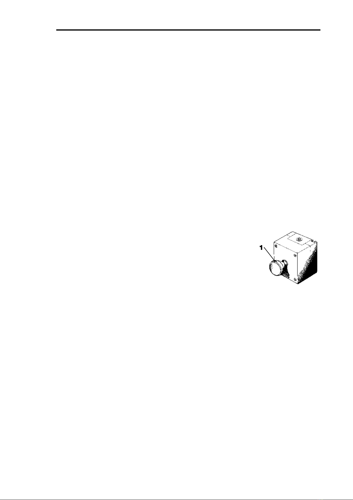
1. Emergency stop
2. Display console.
3. High voltage control unit.
4. Roller unit.
5. PC with brake diagnose program
6. Printer
7. Remote control
Accessories:
Base station for wireless air pressure transducers
Air pressure transducers - wireless
Air pressure transducers - cable connected
1. Emergency stop
Press for emergency stop.
Note: Notice the location of the emergency stop before
starting the brake tester. The emergency stop is not
necessarily positioned in the same place at every installation,
however it will always be installed in the immediate vicinity of
the brake tester.

EB30/EC30/630 Upgrade Page 6
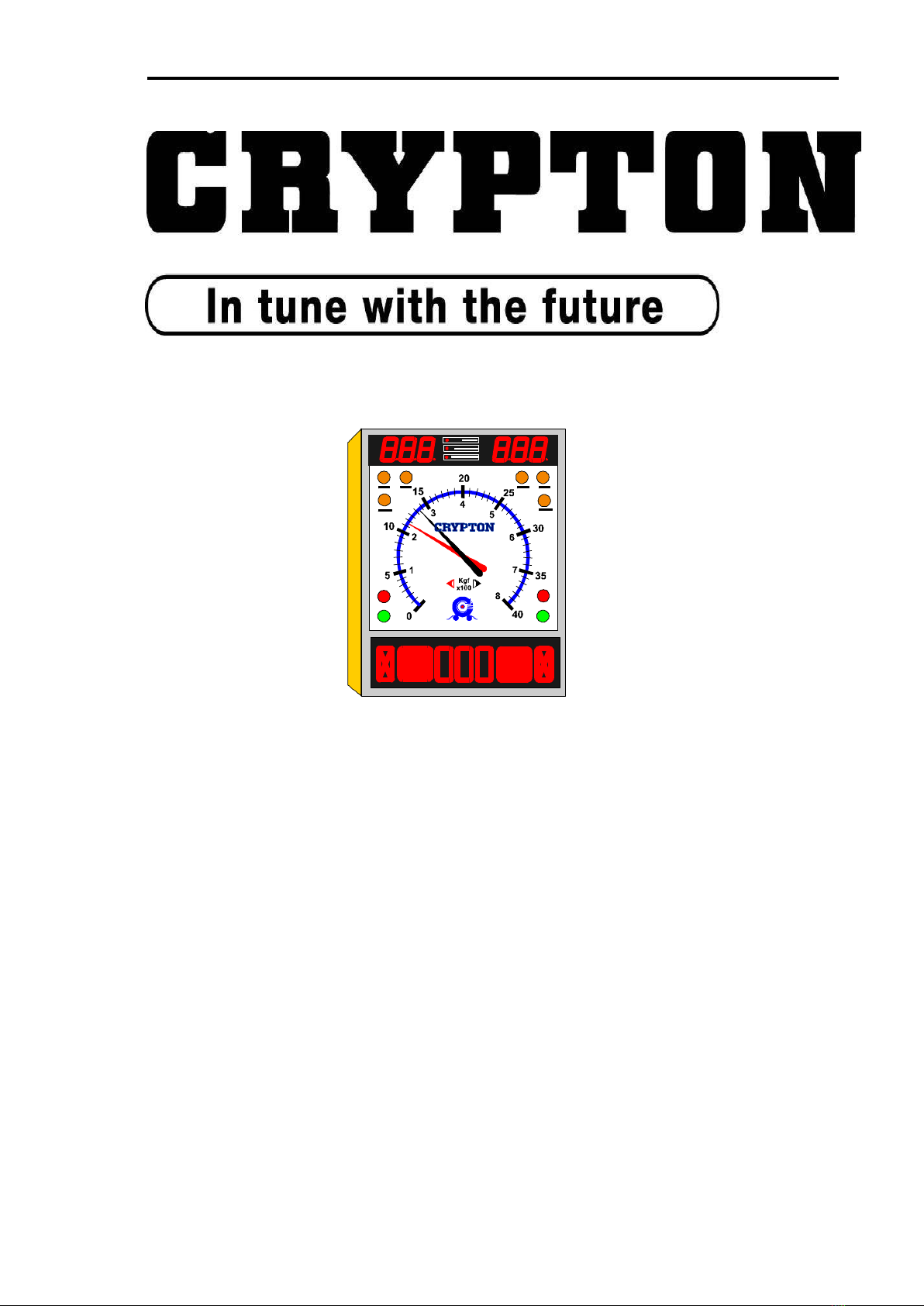
2. Display console
1. Top digital display - air pressure, ovality and weight
2. Indicator showing type of information on top display
3. Indicator light - 4WD (accessory)
4. Indicator light - automatic operation
5. Indicator light - manual operation
6. Indicator light - scale range or 0-800 Kgf)
7. Indicator light - scale range 0-4000 Kgf)
8. Scale showing brake force
9. Pointers; red = left, black = right
10. Amber light - zeroing and fault indicator
11. Red lights - wheel locking
12. Green lights - ready for testing
13. Bottom digital display - imbalance, ovality, pressure and weight

EB30/EC30/630 Upgrade Page 7
3. High voltage control.
1. Keyboard.
2. RESET button (resetting of safety relay).
3. Main switch (power supply circuit breaker).
4. Roller unit.
1. Rollers
2. 3rd roller
Fitted with:
Strain gauge transducer.
Speed sensor on third roller.
Speed sensor on gear box
Proximity sensor on third roller assembly
5. PC with diagnostic program
1. On/off switch
2. PC keyboard
3. Monitor
6. Printer
1. On/off switch
2. Paper tray
3. Cover
7. Remote control
1. Keyboard
2. Battery cover
3. Infrared transmitter window

EB30/EC30/630 Upgrade Page 8
Functions & Facilities
The functions and facilities of the brake tester in alphabetical order.
Automatic operation (not for UK MOT use)
In automatic operational mode, the brake tester will start automatically when a
wheel set is driven onto the rollers and stop either when the wheels lock, when stop
is pressed or when driving out of the rollers.
When the brake tester is turned on it is in automatic mode.
It changes to manual mode when registering a vehicle on the PC.
It returns to automatic operational mode after having concluded a test
or after having pressed PRINT.
If STOP has been pressed so that the AUT and MAN lights are lit.
The brake tester will not start up automatically when driving a wheel
set onto the rollers. Then press STOP again before driving onto the
rollers.
Imbalance
In manual operational mode: Press DAFF after having started the rollers. The
difference of braking effect between the left and right wheel is indicated by the
positions of the pointers. The result is shown at the bottom display (as %).
In automatic operational mode: The imbalance is shown when the brake force
exceeds 40 kgf.
You toggle between imbalance and air pressure by pressing AIR and DAFF.
One-wheel operation (accessory).
In one-wheel operation one wheel is rotating whilst the other is stationary.
Press TEST and START. Choose the wheel by using UP for the left wheel and
DOWN for the right one. The display shows which one has been chosen. Press
START to start the chosen wheel.
One wheel operation is used for MOT testing and to test damaged vehicles.
Four-wheel operation. (accessory).
The brake tester can be fitted with a facility to test four-wheel drive vehicles. This
makes it possible to test one wheel whilst the other wheel on the same axle is
reversing to avoid that the torque is transmitted to other axles during the test.
Brake force is measured only on the non-reversing wheel.
Press 4WD. Drive the first set of wheels onto the rollers and press START. The
green light lights up on the side of the wheel to be tested and the relevant pointer
shows the brake force. Press OK to store the result. Press START to test the other
wheel and press OK to store the result.

EB30/EC30/630 Upgrade Page 9
Choose which wheel to be tested first before starting the test: Press 4WD once to
choose the left wheel (indicated by the left light). Press 4WD again to choose the
right wheel to be tested first. Press a third time to return to normal operation.
Parking brake.
The parking brake is tested in the same way as the foot brake. It is therefore not
necessary to make special concessions for testing the parking brake.
However in manual mode it is necessary to indicate when the parking brake is to
be tested. The reason is that special calculations are used for the parking brakes.
With a wheel set on the rollers press START and choose the transducer using the
UP and DOWN keys. Press START again to start the rollers. Press PARK to
indicate the test of the parking brake.
The bottom display shows momentarily the number of the relevant parking brake,
for example P1. Then the bottom display shows the pressure PM. The top display
shows the chosen pressure Pc.
Printed report.
A report can be printed after a test in manual operational mode. Press the PRINT
key after the last axle has been tested and accepted.
The report shows all relevant calculations both of each individual axle and of the
whole vehicle. The report can also contain relevant graphs.
The content and layout of the report is set up in the program on the PC.
Holding the result on the display.
In both manual and automatic mode the pointers and the LED displays will remain
showing the results after locking the wheels until either restarting the tester,
pressing OK or after 5 minutes have elapsed.
EB30/EC30/630 Upgrade Page 10
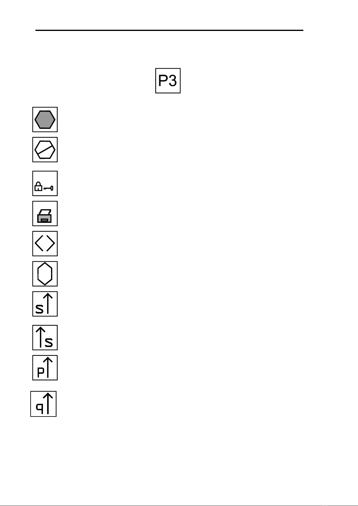
Symbols.
The following symbols will appear on the LED display:
Parking brake and number.
Accept of signal from remote control
Emergency stop activated
The brake tester is locked and does not communicate with PC
The brake tester transmits signal to printer
Imbalance in %
Ovality in %
Testing left secondary brake.
Testing right secondary brake
Testing left parking brake.
Testing right parking brake
This manual suits for next models
2
Table of contents
Other CryptOn Test Equipment manuals


