Fluke COMARK RF500A User manual

RF500A Gateway
Service Manual
Issue 1.0
17 November 2011

Comark RF500A/AP Service Manual
Copyright
Copyrig t © 2011 by Comark Instruments. All rig ts reserved. No part of t is publication may be reproduced,
transmitted, transcribed, stored in a retrieval system, or translated into any language or computer language in any form
or by any means, electronic, mec anical, magnetic, optical, c emical, manual or ot erwise wit out t e prior written
permission of Comark Instruments.
Disclaimer
T e information in t is guide is subject to c ange wit out notice.
Comark Instruments makes no representations or warranties, eit er expressed or implied, wit respect to t e contents
ereof and specifically disclaims any warranties of merc antability or fitness for any particular purpose. Any Comark
Instruments software described in t is manual is licensed “as is”. S ould t e programs prove defective following t eir
acquisition t e user (and not Comark Instruments) assumes t e entire cost of all necessary servicing, repair and any
incidental or consequential damages resulting from any defect in t e software.
17 November 2011 Page 2 of 65

Comark RF500A/AP Service Manual
Contents
Introduction..........................................................................................................................................................................6
Related Documentation...................................................................................................................................................6
Safety Information................................................................................................................................................................7
Warnings.........................................................................................................................................................................7
WEEE..............................................................................................................................................................................7
Specification.........................................................................................................................................................................8
System Block Diagram.........................................................................................................................................................9
Visual Tour..........................................................................................................................................................................10
Front View.....................................................................................................................................................................10
Bottom View.................................................................................................................................................................11
Side View (USB Connector).........................................................................................................................................11
Side View (Serial Number Label).................................................................................................................................12
Top View.......................................................................................................................................................................12
Software Utilities................................................................................................................................................................13
RF500A Config Utility.................................................................................................................................................13
Driver Update Software................................................................................................................................................14
Tftpd32 Software.....................................................................................................................................................14
Hyper-terminal..............................................................................................................................................................15
Hyper-terminal Settings..........................................................................................................................................15
Disassembly........................................................................................................................................................................16
Tools..............................................................................................................................................................................16
Prerequisites..................................................................................................................................................................16
Exploded View..............................................................................................................................................................17
Remove μSDHC Cards.................................................................................................................................................18
Remove Case Front.......................................................................................................................................................19
Remove RF S ield........................................................................................................................................................20
Remove t e PC Module................................................................................................................................................20
Remove t e main PCB from base plate........................................................................................................................21
Remove RF PCB from main PCB.................................................................................................................................22
Fully Disassembled Replaceable Parts.........................................................................................................................23
Reassembly.........................................................................................................................................................................24
Replace Case Front.......................................................................................................................................................24
Tier 1: RF500A Functional Testing....................................................................................................................................25
Operator Tec nical Competency...................................................................................................................................25
Functional Test Equipment Required............................................................................................................................25
Initial Observation.........................................................................................................................................................25
Status Indicators......................................................................................................................................................25
Startup Sequence...........................................................................................................................................................26
Battery Test...................................................................................................................................................................27
Power Over Et ernet (PoE) Testing..............................................................................................................................27
Network Test.................................................................................................................................................................28
Alarm Output Test.........................................................................................................................................................28
Alarm LED Test............................................................................................................................................................29
Radio Module Test........................................................................................................................................................29
Audit Trail & System Software Test ............................................................................................................................29
S utdown Test...............................................................................................................................................................29
Software...................................................................................................................................................................29
Hardware.................................................................................................................................................................29
Tier 2: RF500A Module Replacements..............................................................................................................................30
Operator Tec nical Competency...................................................................................................................................30
Test Equipment Required..............................................................................................................................................30
Initial Observation.........................................................................................................................................................30
Status Indicators......................................................................................................................................................30
Replace t e Battery Pack..............................................................................................................................................31
Replace RF Module......................................................................................................................................................32
Replace PC Module......................................................................................................................................................33
Upload latest drivers................................................................................................................................................33
17 November 2011 Page 3 of 65

Comark RF500A/AP Service Manual
Procedure.................................................................................................................................................................33
Replace μSDHC Cards..................................................................................................................................................35
Replace μSDHC Card 1..........................................................................................................................................35
Replace μSDHC Card 2..........................................................................................................................................36
Replacement of bot μSDHC Cards.............................................................................................................................36
Tier 3: RF500A Component Level Repair..........................................................................................................................37
Operator Tec nical Competency...................................................................................................................................37
Functional Test Equipment Required............................................................................................................................37
Initial Observation.........................................................................................................................................................37
Status Indicators......................................................................................................................................................37
Circuit Diagrams.....................................................................................................................................................37
Circuit Description........................................................................................................................................................38
Power Supply..........................................................................................................................................................38
External Mains Power.............................................................................................................................................38
Power Over Et ernet (PoE).....................................................................................................................................38
Battery.....................................................................................................................................................................38
Main 5V Rail...........................................................................................................................................................38
Permanent 3.3V Rail...............................................................................................................................................38
Control MPU Circuit...............................................................................................................................................38
PC Module...............................................................................................................................................................38
USB.........................................................................................................................................................................39
RF Module...............................................................................................................................................................39
Real Time Clock (RTC)...........................................................................................................................................39
In Circuit Testing...........................................................................................................................................................40
Common Power Rail (Pwr).....................................................................................................................................41
5V Rail....................................................................................................................................................................41
3VM Rail.................................................................................................................................................................41
3VC Rail..................................................................................................................................................................41
Battery C arging.....................................................................................................................................................41
USB C ip Verification.............................................................................................................................................42
Replace PoE Module...............................................................................................................................................43
Control MPU firmware upgrade...................................................................................................................................44
C eck t e Fuses.......................................................................................................................................................45
Program t e Firmware.............................................................................................................................................45
Fault Finding.................................................................................................................................................................46
MPU........................................................................................................................................................................46
Serial Communications...........................................................................................................................................46
USB Communications.............................................................................................................................................46
5V Rail....................................................................................................................................................................46
3VM Rail.................................................................................................................................................................46
3VC Rail..................................................................................................................................................................47
Battery C arging.....................................................................................................................................................47
PoE (If Fitted)..........................................................................................................................................................47
RTC.........................................................................................................................................................................47
Memory Cards.........................................................................................................................................................47
Additional Fault Diagnostic Information......................................................................................................................48
Hardware Status Page..............................................................................................................................................48
Audit Trail Information...........................................................................................................................................49
Email Output Screen...............................................................................................................................................50
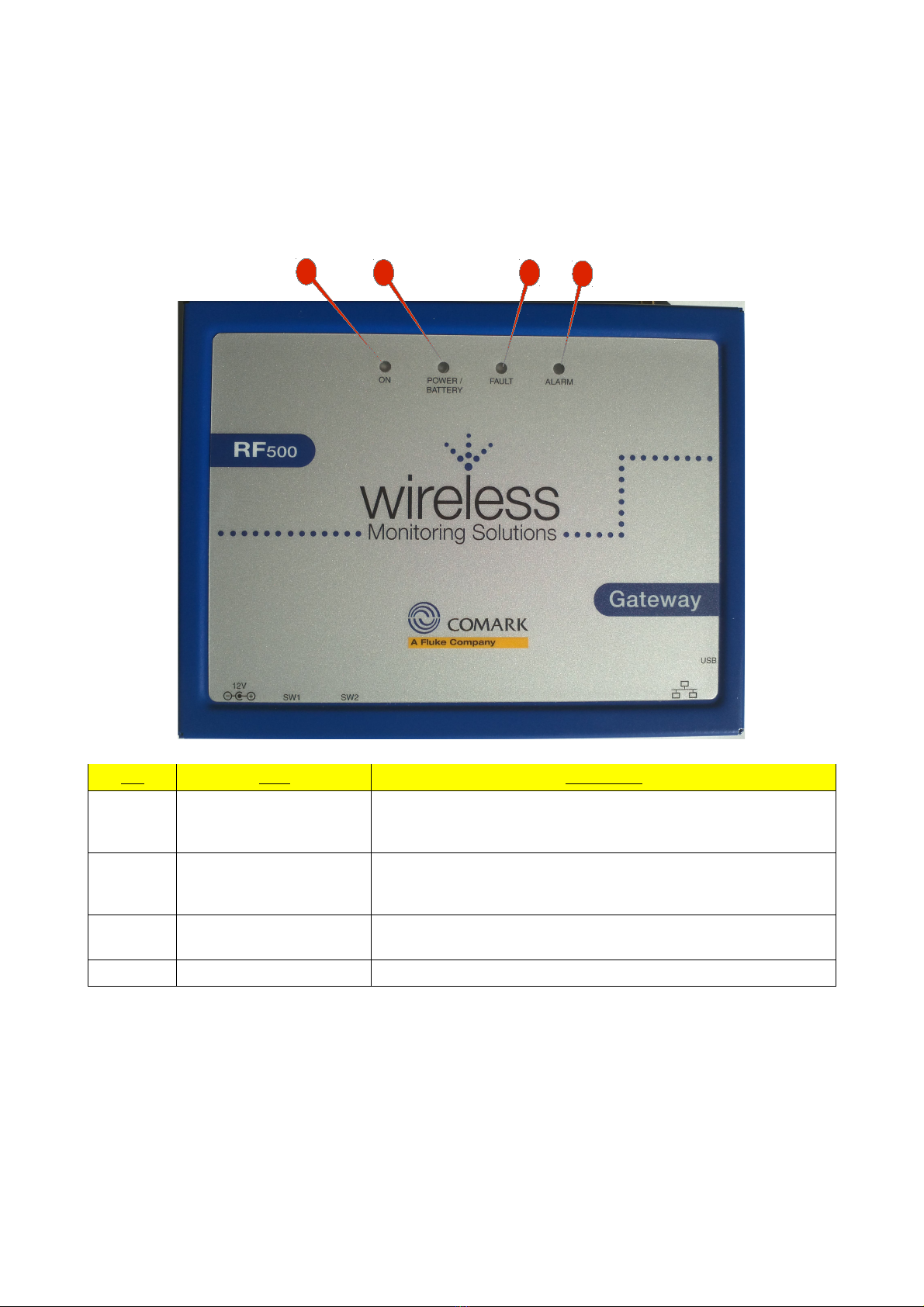
Appendix-A – Front Panel Indicators.................................................................................................................................51
Appendix B – Status Indicators..........................................................................................................................................52
Battery Pack Pre-C arge Indication..............................................................................................................................52
Appendix C – Website Error Messages..............................................................................................................................53
No Hardware Pass message..........................................................................................................................................53
SD cards appear to be in t e wrong slots......................................................................................................................53
SD cards appear to ave different data ID tags ............................................................................................................53
Looks like you ave no data on t e master SD.............................................................................................................53
booted up from backup SD card...................................................................................................................................53
c eck SD card slots possible error wit SD2................................................................................................................54
17 November 2011 Page 4 of 65

Comark RF500A/AP Service Manual
c eck SD card slots possible error wit SD1................................................................................................................54
File Error.......................................................................................................................................................................54
Appendix D – Restore Data to an RF500A/AP..................................................................................................................55
Restore From Manual Backup......................................................................................................................................55
Restore From S ared Drive Backup.............................................................................................................................56
Appendix E – RF500A/AP Hidden Commands.................................................................................................................58
Clear Data Commands..................................................................................................................................................58
clr-data.....................................................................................................................................................................58
clr-datax...................................................................................................................................................................59
Utility Commands.........................................................................................................................................................60
emberlog2................................................................................................................................................................60
ss d..........................................................................................................................................................................61
Connecting wit PuTTY.........................................................................................................................................61
mbklog..........................................................................................................................................................................63
Command List...............................................................................................................................................................63
Appendix F – Repair Procedure for RF500 RADIO MODULE........................................................................................64
Recovery from Transmitter Error 104 Condition..........................................................................................................64
17 November 2011 Page 5 of 65

Comark RF500A/AP Service Manual Introduction
Introduction
T is manual is intended for all aspects of fault diagnosis and repair for t e RF500A/AP. It is structured into 3 tiers of
testing eac requiring more tec nical competence t an t e last. Eac tier indicates t e tec nical requirements at t e
beginning of t e section under t e “Operator Technical Competency” eading.
Familiarity wit use of t e RF500A Gateway is assumed and procedures suc as t ose w ic appear in t e user manual
or RF500A System Manual will not be detailed ere.
Related Documentation
Installation and Basic Operation RF500A System Manual
Web Interface Operation RF500A-WebView Help
RF500A System Manual is supplied in printed form wit eac Gateway
T e above can be downloaded from ttp://www.comarkltd.com/comark-operator-manuals.tpl
17 November 2011 Page 6 of 65

Comark RF500A/AP Service Manual Safety Information
Sa ety In ormation
Under no circumstances may a user make any c anges to t e RF500A Gateway t at would alter its performance. Any
modification would void t e CE compliance of t e Gateway and may invalidate t e warranty.
If t e equipment is used in a manner not specified by Comark Instruments, t en t e protection provided by t e
equipment may be impaired.
Warnings
•Before connecting or disconnecting t e antenna, ensure anti-static precautions are observed.
•Use only t e FRIWO 12V AC adaptor; Type FW74010/12 as supplied; wit t e RF500A Gateway.
•Do not modify t e RF500A Gateway AC adaptor in any way.
•Use only t e PHIHONG, PSM11R-050 5V AC adaptor or FRIWO type FW7662/05 wit RF500 Transmitters.
It is supplied by Comark Instruments as t ree variants:
RF520 Transmitter AC adaptor wit UK plug
RF520/EU Transmitter AC adaptor wit European style plug
RF520/US Transmitter AC adaptor wit Nort American style plug
•Do not modify t e AC adaptor in any way.
•RF500 Transmitters contain a C-size lit ium cell. T is cell must not be incinerated or subjected to temperatures
in excess of 100°C. Do not deform, mutilate, crus , pierce, disassemble, rec arge or s ort circuit. Suc abuse
can result in loss of seal, and/or cell explosion. Also exposure to umid conditions for long periods s ould be
avoided.
•Do not insert metal objects into connectors.
•Ensure t e antenna is securely connected before powering t e equipment. Internal damage may result
ot erwise.
•T e Gateway and Transmitters ave been designed to operate wit t e antenna supplied by Comark, and aving
a maximum gain of 7dBi. Antennas not supplied by Comark Instruments or aving a gain of greater t an 7dBi
are strictly pro ibited for use wit t is device. T e required antenna impedance is 50 O ms. If in doubt please
contact Comark Instruments or your Distributor for advice.
WEEE
RF512, RF513, RF515 and RF516 Transmitters contain a non-rec argeable lit ium battery. T is battery
must be disposed of in accordance wit local regulations.
17 November 2011 Page 7 of 65

Comark RF500A/AP Service Manual Specification
Speci ication
No of C annels Up to 256
No of Transmitters Up to 64
Storage Capacity Up to 10 years storage
RF Frequency 2.4GHz using IEEE 802.15.4
Operating Conditions 0°C to 40°C, 10-90% RH non-condensing
Power Sources
AC power adaptor, rec argeable Ni-M battery
RF500AP only:
Power over Et ernet (PoE) capability. Compliant to
IEEE 802.3af
Power Adaptor 100-240VAC 1.5A 50/60Hz
FRIWO DT12 12V 1A O/P
Battery Backup 4.3A Ni-M Rec argeable Battery.
Running time approximately 1 our
Clock Accuracy 4ppm (2 minutes per year)
Relay Outputs (SW1 & SW2) Two individual 2.5mm jack sockets.
Contacts: 24Vdc 500mA maximum
Power Consumption 12W Max
Dimensions L 225mm x W 150mm x D 40mm
Weig t 1.3kg
17 November 2011 Page 8 of 65

Comark RF500A/AP Service Manual System Block Diagram
System Block Diagram
17 November 2011 Page 9 of 65

Comark RF500A/AP Service Manual Visual Tour
Visual Tour
Front View
No. Item Description
1ON Steady Blue: Gateway is running
¼s on ¼s off Blue : Gateway is starting up
2s off 2s on Blue: Gateway is s utting down
2POWER/BATTERY Steady Green: External Power is available
Flas ing Green: Gateway is on and running off t e battery pack
Off: Gateway is off and external power is not available
3FAULT Flas ing: T ere is a fault wit t e system, could indicate ardware or
software fault
4ALARM Flas ing Red: An enabled alarm event as occurred
17 November 2011 Page 10 of 65
13
24

Comark RF500A/AP Service Manual Visual Tour
Bottom View
No. Item Description
1Cable Clamp To secure cables during installation
212V DC Input Input for Friwo DT12 external power adapter
3W1 Jack Socket for Relay Output 1
4W2 Jack Socket for Relay Output 2
5RJ45 ocket RJ45 Et ernet LAN Socket
6Cable Clamp To secure cables during installation
Side View (USB Connector)
No. Item Description
1U B Used for initial configuration and as a debug port using t e RF500A
Config software or Hyper-terminal (or similar comms program)
2Memory Card Door For access to bot μSDHC cards
3Module Reset Direct access to t e PC module reset line
17 November 2011 Page 11 of 65
1
3 4
2
5
6
12
3

Comark RF500A/AP Service Manual Visual Tour
Side View (Serial Number Label)
No. Item Description
1Model Indicates w ic build variant t e unit is (RF500AP is t e PoE version)
2ON/OFF witch Gateway Startup/Powerdown switc
3tatus LED's Diagnostic LEDs (See Fault Code table)
4AUX Button Not Used
op View
No. Item Description
1Antenna Port RP-SMA Connector for standard or i-gain antenna
17 November 2011 Page 12 of 65
1
1
234

Comark RF500A/AP Service Manual Software Utilities
So tware Utilities
RF500A Config Utility
T is accompanying software is released to t e customer to allow basic configuration of t e unit via t e USB interface.
Additionally it can provide a status report to aide fault finding.
To use t e software Java 1.6.0 or ig er must be installed, t e installer can t en be run and t e utility will be installed
on t e target mac ine.
Run t e application wit an RF500A/AP turned on and connected to t e PC via t e USB port, enter t e serial number
and click “View Current Settings”:
No. Item Description
1View Current ettings View settings of unit
2oftware Issue SW refers to t e software issue currently running on t e unit
HW refers to t e firmware version currently running on t e control MPU
3Comms Port T is is t e USB virtual com port currently being used
4Generate Report File Will output a text file wit status information
5erial Number Serial number of t e unit to be interrogated
6ave New ettings Once new settings are entered in t e relevant boxes t is will initiate t e
upload of t ose settings to t e unit
7MAC Address T is is t e MAC address of t e unit
8IP Address T is is t e current IP address of t e unit (t is can be c anged and saved
back to t e RF500A/AP)
9Net Mask T is is t e current Net Mask of t e unit (t is can be c anged and saved
back to t e RF500A/AP)
10 Default Gateway T is is t e current Default Gateway IP address of t e unit (t is can be
c anged and saved back to t e RF500A/AP)
17 November 2011 Page 13 of 65
5
8
9
10
6
2
3
1
7
4

Comark RF500A/AP Service Manual Software Utilities
Driver Update Software
T e stock PC module requires custom drivers to be installed before it can be used in an RF500A/AP. A simple software
utility is available to apply t e update. T e system uses t e USB port for control and t e Et ernet port for t e actual
data transfer.
On t e same PC running t is update utility Tftpd32 must be installed and running, and t e latest drivers installed into
C:\tftp.
No. Item Description
1Enter RF500A serial Number Serial number of t e target RF500A/AP
2RF500 IP address IP address of t e target RF500A/AP
3TFTP erver IP IP address of t e PC running t e update software
4Update MXM6410 Driver 1 Start Driver 1 update process
5Update MXM6410 Driver 2 Start Driver 2 update process
T tpd32 So tware
To perform t e driver update a tftp (Trivial File Transfer Protocol) server need to be running on t e same PC as t e
driver update software.
Tftpd32 can be obtained from ttp://tftp32.jounin.net
T is software must be configured as s own below:
17 November 2011 Page 14 of 65
1
2
3
4
5

Comark RF500A/AP Service Manual Software Utilities
Hyper-terminal
Furt er access to t e RF500A/AP can be gained using a terminal program suc as Hyper-terminal. Root access can be
ac ieved via t e USB port for furt er fault diagnosis.
Hyper-terminal Settings
No. Item Description
1Comms Port T is is t e Virtual Com Port created by t e USB drives (if t e number is
not known it can be found in Device Manager → Ports)
2Login Prompt Indicates connection as been establis ed and is now waiting for login
credentials
17 November 2011 Page 15 of 65
1
2

Comark RF500A/AP Service Manual Disassembly
Disassembly
ools
To disassemble an RF500A/AP you will need t e following tools:
•Wrist grounding strap and conductive mat for preventing electrostatic disc arge
•P illips screwdriver
•8mm box driver
•5mm box driver
•T in nose pliers
Prerequisites
1. Turn off t e RF500A/AP.
2. Remove AC power.
3. Place on a flat stable surface.
4. Remove t e antenna.
17 November 2011 Page 16 of 65

Comark RF500A/AP Service Manual Disassembly
Exploded View
17 November 2011 Page 17 of 65

Comark RF500A/AP Service Manual Disassembly
Remove μSDHC Cards
T e memory cards are located be ind t e metal
plate located on t e USB connector side of t e unit:
Remove t e 2 retaining screws:
T e memory cards are now exposed and can be
removed. To eject t e card simply pus t e card in
until a click is eard and t en release:
T e cards are now ready to be removed:
17 November 2011 Page 18 of 65

Comark RF500A/AP Service Manual Disassembly
Remove Case Front
Remove t e 8 case retaining screws securing t e case front to t e case rear:
USB Side View
Serial Number Side View
Top View
Bottom View
T e case front can now be carefully removed.
NOTE: DISCONNECT BATTERY BEFORE ROCEEDING ANY FURTHER.
17 November 2011 Page 19 of 65

Comark RF500A/AP Service Manual Disassembly
Remove RF Shield
Remove t e 3 retaining screws:
Once t e retaining screws ave been removed t e s ield will simply lift off.
Remove the PC Module
Remove t e 2 exagonal pillars wit t e 5mm box driver:
Once t e pillars ave been removed t e module will self locate for removal.
17 November 2011 Page 20 of 65
Other manuals for COMARK RF500A
1
This manual suits for next models
4
Table of contents
Other Fluke Gateway manuals
Popular Gateway manuals by other brands

RTA
RTA 460TCPA-NNA1 Product user guide

TP-Link
TP-Link Deco X50-4G user guide

CONTROL SOLUTIONS
CONTROL SOLUTIONS Babel Buster 3 BB3-6101-GW user guide

Balluff
Balluff Subnet16 BIS Z-GW-001-PBS installation guide

Grandstream Networks
Grandstream Networks GXW42XX V2 Quick installation guide

Wave Broadband
Wave Broadband Home Network Gateway user guide