manuals.online logo
Brands
  1. Home
  2. •
  3. Brands
  4. •
  5. Fluke
  6. •
  7. Measuring Instrument
  8. •
  9. Fluke 82RF User manual

Fluke 82RF User manual

Other Fluke Measuring Instrument manuals

Fluke i800 User manual

Fluke

Fluke i800 User manual

Fluke 971 User manual

Fluke

Fluke 971 User manual

Fluke OptiView III Series User manual

Fluke

Fluke OptiView III Series User manual

Fluke PM6669 User manual

Fluke

Fluke PM6669 User manual

Fluke DSP-FOM Operating and installation instructions

Fluke

Fluke DSP-FOM Operating and installation instructions

Fluke Hart Scientific 914 Series User manual

Fluke

Fluke Hart Scientific 914 Series User manual

Fluke 1736 User manual

Fluke

Fluke 1736 User manual

Fluke PG7607 User manual

Fluke

Fluke PG7607 User manual

Fluke 1742 Configuration guide

Fluke

Fluke 1742 Configuration guide

Fluke NORMA 6003 User manual

Fluke

Fluke NORMA 6003 User manual

Fluke 095969674225 User manual

Fluke

Fluke 095969674225 User manual

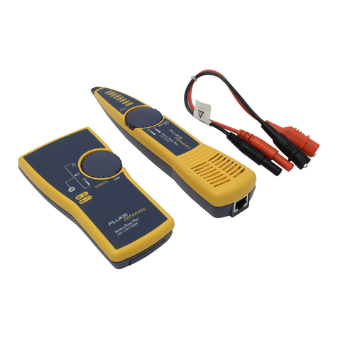
Fluke IntelliTone Pro 200 LAN User manual

Fluke

Fluke IntelliTone Pro 200 LAN User manual

Fluke FL700G01 User manual

Fluke

Fluke FL700G01 User manual

Fluke BT520 User manual

Fluke

Fluke BT520 User manual

Fluke VIBGUARD compact User manual

Fluke

Fluke VIBGUARD compact User manual

Fluke 481-DESI Instruction manual

Fluke

Fluke 481-DESI Instruction manual

Fluke i400s User manual

Fluke

Fluke i400s User manual

Fluke 373 User manual

Fluke

Fluke 373 User manual

Fluke i40s-PR 1750 40A User manual

Fluke

Fluke i40s-PR 1750 40A User manual

Fluke TS54 TDR User manual

Fluke

Fluke TS54 TDR User manual

Fluke 789 User manual

Fluke

Fluke 789 User manual

Fluke 411D User manual

Fluke

Fluke 411D User manual

Fluke RUSKA 2482 User manual

Fluke

Fluke RUSKA 2482 User manual

Fluke 5020AThermo-Hygrometer 5020A User manual

Fluke

Fluke 5020AThermo-Hygrometer 5020A User manual

Popular Measuring Instrument manuals by other brands

Powerfix Profi 278296 Operation and safety notes

Powerfix Profi

Powerfix Profi 278296 Operation and safety notes

Test Equipment Depot GVT-427B user manual

Test Equipment Depot

Test Equipment Depot GVT-427B user manual

Fieldpiece ACH Operator's manual

Fieldpiece

Fieldpiece ACH Operator's manual

FLYSURFER VIRON3 user manual

FLYSURFER

FLYSURFER VIRON3 user manual

GMW TG uni 1 operating manual

GMW

GMW TG uni 1 operating manual

Downeaster Wind & Weather Medallion Series instruction manual

Downeaster

Downeaster Wind & Weather Medallion Series instruction manual

Hanna Instruments HI96725C instruction manual

Hanna Instruments

Hanna Instruments HI96725C instruction manual

Nokeval KMR260 quick guide

Nokeval

Nokeval KMR260 quick guide

HOKUYO AUTOMATIC UBG-05LN instruction manual

HOKUYO AUTOMATIC

HOKUYO AUTOMATIC UBG-05LN instruction manual

Test Products International SP565 user manual

Test Products International

Test Products International SP565 user manual

General Sleep Zmachine Insight+ DT-200 Service manual

General Sleep

General Sleep Zmachine Insight+ DT-200 Service manual

Sensa Core Lacto Spark user manual

Sensa Core

Sensa Core Lacto Spark user manual

VOLTCRAFT UTS-1980 operating instructions

VOLTCRAFT

VOLTCRAFT UTS-1980 operating instructions

EBCHQ 94915 Operation manual

EBCHQ

EBCHQ 94915 Operation manual

Balluff BIP LD2-T017-01-EP-S4 Series user guide

Balluff

Balluff BIP LD2-T017-01-EP-S4 Series user guide

Pulsar IMP Lite Series instruction manual

Pulsar

Pulsar IMP Lite Series instruction manual

ETCR 6800 user manual

ETCR

ETCR 6800 user manual

IRIMO 984-6D-1 owner's manual

IRIMO

IRIMO 984-6D-1 owner's manual

manuals.online logo
manuals.online logoBrands
  • About & Mission
  • Contact us
  • Privacy Policy
  • Terms and Conditions

Copyright 2025 Manuals.Online. All Rights Reserved.

L8Z./U LA3H 9Z.61 M3jelAl 08Q8£t? N/d
(indui avo| oi Qq) sjbuiuijsi indui stJ3i3uii{OA
3qj oj jopsuuoo indjno spqojd sqi 103111103 p
’(indui suij y\i jsd 8uipB3j
op \\) 3§ubj sSbijoa siBudoaddB ub psps '£
(•AiqiqBduio;} JopuiijOA 33 s) ’psiinbsj
Ji ‘iunqs 3}qBims bqiiA\ JSpuiqoA sqi dmbg -3
J313UI 1|0A 3|qilBdUi 03 B3ZI§J 3U3pUB 1D3J3S‘\
:9Cl0J d38 9M1oi^Jodo 01 3jnp330id guiA\oqoj sqi 3sq
NOI±Vd3dO
'3o jsd uoiiBoypsds
oiibj J3jsuBii op-oi-DB jo roS? :iua|0|jjaoo ajn)ejaduidi
jd Ol> paiunqs 3:aouapaduj| }ndu|
*9PA003 SUIJ Aoe *Bbhoa mdu| wnuqxBw
sun AOe 01 53 0:eBuey aBajiOA
‘3AB,W 3UIS BJO 3n|BA SUIJ pB3J 01 p31BJqi[BD
si puB ‘indui jo 3njBA >fB3d oi spuods3>i :asuodsay
mnooloi zH^f oz sSuipbsj
3aiib|3j joj jnjssfj :asuodsay Aouanbajj papuaix^
*jd 003 ui?qi ss3{ Aq
psiunqs %0IT UW 01 J° uoiibuiujjsi indino sqoad bpue
J3idBpB spqojd aqi jo ssn sqi 3UinssB suoiiBoijpsds
OI1BJ J3JSUBJ1 3P-01-3B pUB 3SUodS3J Aou 3nb3J J
*
uw rn 06
0001
01 -001
01 •001
‘UN 001
=sy
=^JI
:3{duiBX3
’(UN OK) UN u!33ubisis3j indui jspuiijoa =ui-y
'UN u!30ubisis3j paiunqs —sy
9P S*IT AOe oi OS
8P O' IT AOS oi 0*3
ap SOT A0'3 01 S*0
ap SIT AS*0 oi 53 0
AOe 01 0*5
AO Soi o*3
A0'3 oi 50
AS’O oi 53'0
IQdinO 30 (ZHN 01)
indui SNd
:3J3q M
01 -d
01 •
:sa\o|{oj
SB p3UlUUJ313p SI pUB \J J/^ QI 01 30UB1SIS3J indui 3qi 33np3J
01 P3P3[3S SI snjBA iunqs 3qi s{buiuij3j indui jpqi ssojdb
psoBjd si iunqs jbujsixs ub ji pssn sq ubd ssoubisissj indui
jsqgrq qiiAV si3i3Uii{Oy\ %01T UN 01 J° 93ubisis3j indui
ub SBq iBqi J3i3uii[OA op Aub qii-\\ 3|qiiBduiOD si ja38 9MI
A±lliailVdWOO H3±3IAinOA
•3qojd qipw
pspiAojd si jsjdBpB 3^9 uo-dqs aopauuoo Ajossaoov
SJ01D3UU0D BUBUBq
|Bnp psoBds qoui 53*0 pjBpuBis siij JopauuoQ jndino
:(OoST €2) *0|py jajsuBjj. oa-oi-QV
ap ST ZHN 00S 01 ZHN 003
ap IT ZHN 003 01 zm 001
:(0|iey jdjsuBjj. oa-oi-QV 01 aApeiay)
4asuodsay Aouanbaj
j
SNOI±VOIdl33dS
indui 3ABAV 3UIS
*•
b jo anjBA suij oqj oj juaiBAinba aq oj pajiuqiiBD si jndjno
Dp s.aqojd aqx suu Aoe oj gj’o jo d8uiu bsapripui puB
SISBq PIEUO pDqSIjduiODDB SI Dp-OJ-DB UIOJJ U0ISJ 3AU03
•JDJDUHIOA DB (ZHM 005 OJ 001
)
^OUDnbDJj
qSiq bojui jdjdujj|oa op bjjdauod oj pauSisap aqojd
Xjossdddb XouanbDjj qgiq bsi (
\
djiiSi
.
1)j-g jg ppop\ aqx
NOiionaouiNi
sqoJd Aouanbsjj q6ju
jeaqS uoqoru^sui
82 RF
Figure 1. 82RF High Frequency Probe
5. Connect the probe’s ground lead to signal
common.
CAUTION
To avoid short circuit damage, never connect
the probe ground lead to apotential other than
ground unless the voltmeter is equipped with a
floating low Input (i.e., not grounded).
6. Contact the measurement point with the probe
tip and read the rms voltage level directly from the
voltmeter. Measurements above 100 MHz require
the use of the BNC adapter and aterminated
system.
CAUTION
To avoid probe damage the dc components or
the input signal must not exceed 200 volts,
including transients. 30V ac rms and 200V dc
are the maximum inputs to the probe. These
specifications allow measurements of an ac
signal riding on adc voltage of up to 200V.
When this type of measurement is being made,
the input capacitor will charge to the peak
value of ac plus dc. If the dc level is then
changed by more than 200V, the resulting
transient may damage the probe. The chance
of damage can be minimized by discharging
the input capacitor at the end of each
measurement. This is done by momentarily
touching the probe tip to the ground clip.
THEORY OF OPERATION
Circuitry within the 82RF consists of acapacitor-coupled
rectifier circuit which responds to the peak value of the
input waveform. The output is positive polarity dc
voltage which is calibrated to be equivalent to the rms
value of asine wave input. See Figure 2. Resistors, R1,R2
and R3 are selected to properly scale the dc output when
connected across adc voltmeter having a10 MH input
resistance.
Figure 2. 82RF Simplified Circuit Diagram
2
82RF
MAINTENANCE
Calibration Adjustment
The following procedure assumes the use of the
equipment (or equivalent) listed in Table 1. Make sure
that the DMM has an input impedance of 10 Mfl ±10%
shunted by less than 200 pF.
1. Complete the test set-up shown in Figure 3.
2. Set the DMM to read 2.00V dc.
NOTE
Accurate results cannot be obtained unless
the signal is terminated with 50£l near the
measurement point.
3.
Program the signal generator for an output of
10 MHz at alevel of 1.00V rms, TERM. (500
instrument).
4. Check the DMM reading, it should be between
±0.95 and 1.05V dc. If the reading is within limits,
calibration adjustment is not required. Complete
the remaining steps if adjustment is necessary.
5. The calibration adjustment is located in the
DMM connector portion of the 82RF. Refer to
Figure 4and access the adjustment using the
appropriate procedure.
6. Using aplastic adjusting tool, adjust the
calibration pot for aDMM reading of 1.00V.
7. Reassemble the probe and verify that the
DMM reading is still within limits.
Cleaning
Use asoft cloth dampened in amild solution of detergent
and water to clean the 82RF. Do not use solvents.
Table 1. List of Recommended Test Equipment
3
82RF
Figure 3. Equipment Connections for Calibration
Remove both screws
and the cover.
B
Remove screw Aand its stud. Swing
enclosure open. Do not remove screws B
Figure 4. Adjustment Access Details
4
John Fluke Mfg, Co.rlnc.#P.O. Box 43210#Mountlake Terrace, Washington 98043
Fluke (Nederland) B.V.#P.O. Box 50539Tilburg, The Netherlands