Fluke FI-500 FiberInspector Micro User manual

September 2016, Rev. 1 9/2016
2016 Fluke Corporation
All product names are trademarks of their respective companies.
FI-500
FiberInspector™Micro
Video Microscope
Users Manual
The FI-500 FiberInspector Micro video microscope is a hand-held probe and
display used to inspect fiber optic endfaces on patch cord and bulkhead
connectors.
WSafety Information
WWarningX
To avoid possible fire, electric shock, personal injury, or damage to the
video microscope:
Carefully read all instructions.
Read all safety information before you use the Product.
Use the Product only as specified, or the protection supplied by the
Product can be compromised.
Use this Product indoors only.
Do not use the Product around explosive gas, vapor, or in damp or
wet environments.
Do not use the Product if it operates incorrectly.
Do not use the Product if it is damaged.
Disable the Product if it is damaged.
Remove the batteries if the Product is not used for an extended
period of time, or if stored in temperatures above 50 °C. If the
batteries are not removed, battery leakage can damage the
Product.
The battery door must be closed and locked before you operate
the Product.
Do not put metal objects into connectors.
www. .com information@itm.com1.800.561.8187

2
Safety and Compliance Symbols
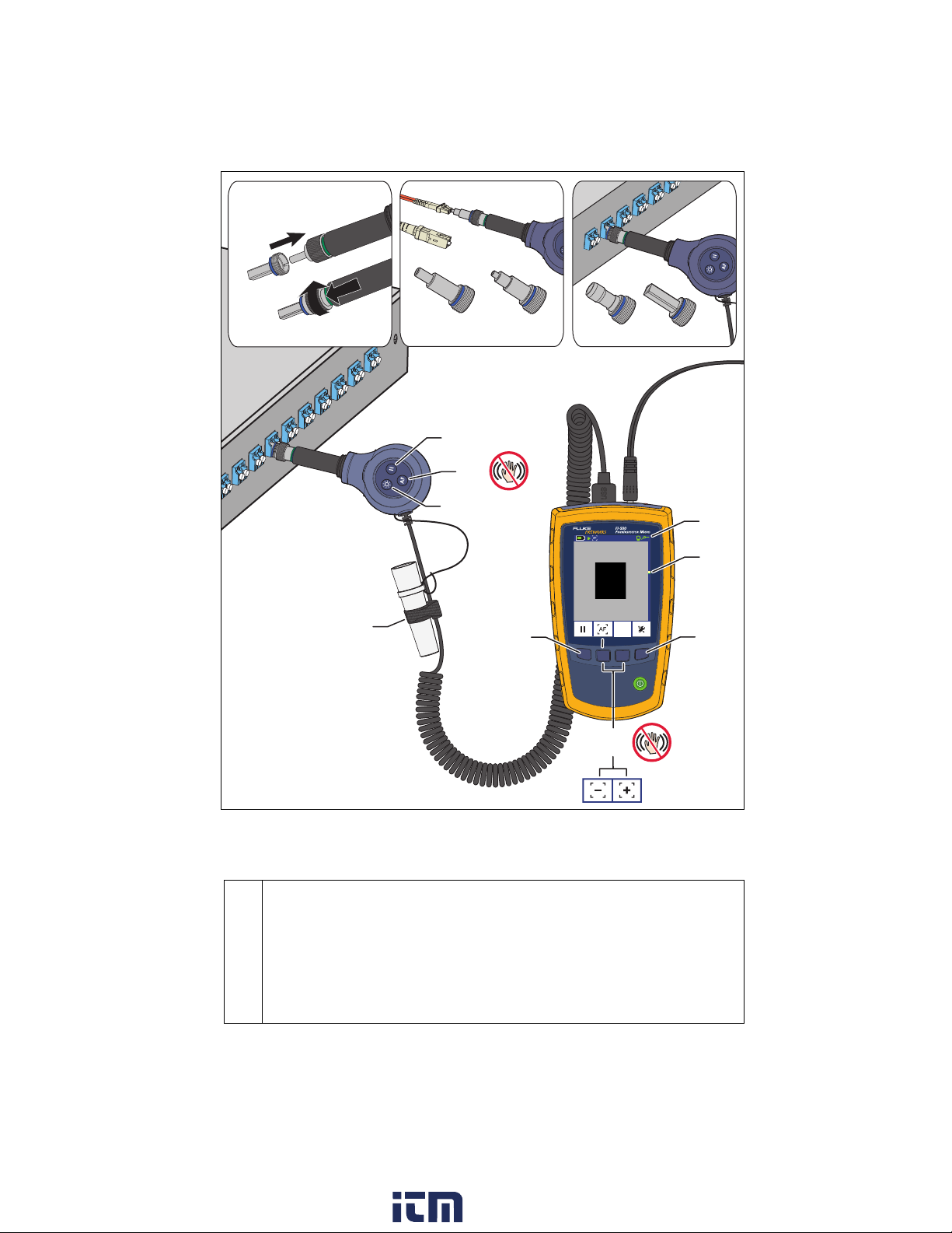
Features and Use
Refer to Figure 1.
WWarning or Caution: Risk of damage to or destruction of equipment or
software.
See the user documentation.
XWarning: Risk of electrical shock.
PConforms to relevant European Union directives
Conforms to relevant Australian standards
40 year Environment Friendly Use Period (EFUP) under China
Regulation - Administrative Measure on the Control of Pollution
Caused by Electronic Information Products. This is the period of time
before any of the identified hazardous substances are likely to leak
out, causing possible harm to health and the environment.
ÃKCC-REM-FKN-012001001: EMC approval for Korea
Class A Equipment (Industrial Broadcasting & Communication
Equipment)
This product meets requirements for industrial (Class A)
electromagnetic wave equipment and the seller or user should take
notice of it. This equipment is intended for use in business
environments and is not to be used in homes.
~This product complies with the WEEE Directive marking requirements.
The affixed label indicates that you must not discard this electrical/
electronic product in domestic household waste. Product Category:
With reference to the equipment types in the WEEE Directive Annex I,
this product is classed as category 9 "Monitoring and Control
Instrumentation" product. Do not dispose of this product as unsorted
municipal waste.
To return unwanted products, contact the manufacturer’s web site
shown on the product or your local sales office or distributor.
Charge the batteries for about 4 hours before you use
them for the first time. See “Charge the Batteries” on
page 7. To ensure continuous operation, connect the ac
adapter whenever possible.
www. .com information@itm.com1.800.561.8187

3
AM00.EPS
Figure 1. Features and Use
Screw an adapter tip onto the fiber probe to match the connection you
will inspect. Tips with blue rings are for PC and UPC connectors. Tips
with green rings are for APC connectors.
WCaution
To avoid damage to the probe, use only tips specified for the
FI-500. Do not use tips from other video microscopes.
SC LC
D
C
B
A
E
W
F1 F2 F3 F4
C
F
D
G
H
SC (U25) LC (U125)
Cap holder
www. .com information@itm.com1.800.561.8187

4
In live mode when the Auto Focus setting is
On, press AF to automatically focus the
image.
In live mode when the Auto Focus setting is
Off, press +and - to focus the image
manually.
Keep the probe still when you use the auto
focus function.
Switch the probe between live and paused
modes. Figure 2 shows the button functions
in paused mode.
Turns the probe light on and off.
See “Settings” on page 6.
The blue, vertical bar is the range of focus. The yellow mark shows
where the focus is within that range. The green mark shows where
the image will be focused.
The probe is connected.
The probe is not connected.
The display does not recognize the
connected probe.
Shows you when the display is live or paused.
Shows you the display’s focus mode. AF is
auto focus. MF is manual focus. See
“Settings” on page 6.
A USB drive is connected to the display.
www. .com information@itm.com1.800.561.8187

5
AM04.EPS
Figure 2. Image Controls
View APC Endfaces
Probe tips for APC (angled physical contact) connectors have a green ring
(Figure 3). When you view an APC endface, rotate the probe or the connector
while you use the auto focus function until you get the best image. If you
cannot get a good image, focus the image manually.
AM08.EPS
Figure 3. APC Tip and Connector Examples
Zoom
Horizontal
Vertical
Live image
Focus automatically or manually. See
Auto Focus under "Settings".
Paused image
Magnify and move the image.
Green
ring
Angled
ferrule
Green
housing
SC bulkhead tip
Green
ring
1.25 mm
connector tip
SC
connector
www. .com information@itm.com1.800.561.8187

6
Settings
Refer to Figure 4.
Display and probe software versions: If a software update is available, you
can download it from the Fluke Networks website. See "Upgrade the
Software".
Power Down: The display turns off after the selected period of inactivity.
Standby: The display goes into low-power mode after the selected period
of inactivity.
Dim Display: The display dims after the selected period of inactivity.
Probe Light: The probe light stays on for the selected time.
Brightness: Changes the brightness of the display. Keeping the display at
less than 100% brightness increases the battery life.
Dimmed Brightness: Changes the brightness of the display when the
display is dim.
Auto Focus
On: Press on the probe or on the display to focus the image
automatically. The display will also focus the image automatically when
you press on the probe or on the display.
Off: Press to focus the image manually.
Save and Exit: Saves the settings and exits the settings menu.
AM02.EPS
Figure 4. Settings
Select a setting Change the setting
www. .com information@itm.com1.800.561.8187

7
Charge the Batteries
WWarningX
To avoid possible fire, electric shock, personal injury, damage to the
video microscope, or incorrect operation:
Use only the ac adapter/charger provided to power the display and
charge the batteries.
Disconnect the battery charger and move the Product or batteries
to a cool, non-flammable location if the rechargeable batteries
become hot (>50 °C, >122 °F) during the charge period.
Do not recharge non-rechargeable batteries.
Batteries contain hazardous chemicals that can cause burns or
explode. If exposure to chemicals occurs, clean with water and get
medical aid.
Repair the Product before use if the battery leaks.
Do not keep cells or batteries in a container where the terminals
can be shorted.
Do not put battery cells and battery packs near heat or fire. Do not
put in sunlight.
When the battery charges, the LED is red. Charge the batteries
for about 4 hours before you use them for the first time.
The charger is connected and no batteries are installed.
When the battery is fully-charged, the LED is green. Fully-
charged batteries last about 3 hours when the display is on
continuously.
When the battery is very low, the battery icon shows a red bar.
The LED blinks red and green and the yellow battery icon shows
if you connect the power adapter when the wrong type of
batteries are installed. See the specifications for the correct
battery types.
The microscope will operate with alkaline batteries, but they will
drain quickly. The display will not try to charge alkaline batteries.
www. .com information@itm.com1.800.561.8187

8
Maintenance
WWarningX
To prevent possible electrical shock, fire, or personal injury:
Do not operate the Product with covers removed or the case open.
Hazardous voltage exposure is possible.
Use only specified replacement parts.
Have an approved technician repair the Product.
Clean the LCD display with a soft, lint-free cloth.
Clean the display and probe housings with a soft cloth dampened with water or
a mild detergent. Do not use solvents or abrasive cleansers.
If the probe lens is dirty, clean it with optical-grade cleaning supplies.
Replace the Batteries
WWarningX
Replacement cells used shall have closely matched capacities, be of
the same design, be of the same chemistry and be from the same
manufacturer and age.
Use only the specified type of batteries, correctly installed, to
power the display. See the specifications for battery types.
Replace the rechargeable batteries after 5 years of moderate use or 2
years of heavy use. Moderate use is defined as recharged twice a
week. Heavy use is defined as discharged to cutoff and recharged daily.
Replace the NiMH batteries at intervals described under “Charge the Batteries”
on page 7. Figure 5 shows how to remove and install the batteries.
AM01.EPS
Figure 5. Replace the Batteries
W
Rechargeable NiMH,
1.2 V, 2200 mAh*
* Fluke Networks recommends Gold Peak GH230AAHC batteries. Use only
NiMH batteries. Do not use other types of batteries.
www. .com information@itm.com1.800.561.8187

9
Upgrade the Software
If new software is available, you can download it from the Fluke Networks
website at no charge. Figure 6 shows how to install new software in the display
and probe.
Refer to Figure 6.
Download the upgrade file from the Fluke Networks website to the root
folder of a USB drive. If the file is a .zip file, unzip the files before you put
them on the USB drive.
Connect the drive to the display. The software update icon shows in the status
bar, and the display imports the upgrade file. The screen shows the software
versions loaded from the USB flash drive (Figure 7).
If there is not a software update file in the root folder of the drive or if you
press Exit, the USB drive icon shows:
Connect the probe to the display.
To upgrade the software, press OK.
To cancel the upgrade, press Exit.
When the upgrade is completed, press Exit to restart the display.
AM06.EPS
Figure 6. Upgrade the Software
Get Service
Contact Fluke Networks for information on authorized Fluke Networks service
centers.
BC
A
D
www. .com information@itm.com1.800.561.8187

10
AM07.EPS
Figure 7. Software Update Screen with the USB Drive Connected
Register Your Product
Registering your product with Fluke Networks gives you access to valuable
information on product updates, troubleshooting tips, and other support
services. To register, fill out the online registration form on the Fluke Networks
website.
www. .com information@itm.com1.800.561.8187

11
Open Source Software
This product uses freeRTOS and FatFS software. The software license statements and
files that contain the binary and source code for the open source software are on the
CD supplied with the product and on the Fluke Networks website. For more
Specifications
General Specifications
Temperature
range* Operating: 32 °F to 122 °F (0 °C to +50 °C)
Storage: -22 °F to +140 °F (-30 °C to +60 °C)
Humidity
range Operating: 0 % to 95 % (32 °F to 95 °F, 0 °C to 35 °C)
RH non-condensing
Storage: 0 % to 95 % (95 °F to 113 °F, 35 °C to 45 °C)
RH non-condensing
Altitude Operating: 4,000 meters; Storage: 12,000 meters
Vibration 2 g, 5 Hz to 500 Hz
Shock 1 meter drop test
Safety IEC 61010-1: Pollution Degree 2
EMC IEC 61326-1: Controlled Electromagnetic Environment; IEC 61326-2-1
CISPR 11: Group 2, Class A
Group 2: Equipment contains ISM RF equipment in which radio-
frequency energy in the frequency range 9 kHz to 400 GHz is
intentionally generated and used or only used, in the form of
electromagnetic radiation, inductive and/or capacitive coupling, for
the treatment of material or inspection/analysis purposes.
Class A: Equipment is suitable for use in all establishments other than
domestic and those directly connected to a low voltage power supply
network which supplies buildings used for domestic purposes. There
may be potential difficulties in ensuring electromagnetic
compatibility in other environments, due to conducted and radiated
disturbances.
USA (FCC): 47 CFR 15 Intentional Radiators: This device complies with
part 15 of the FCC Rules. Operation is subject to the following two
conditions: (1) This device may not cause harmful interference, and
(2) this device must accept any interference received, including
interference that may cause undesired operation. (15.19). Changes or
modifications not expressly approved by Fluke could void the user's
authority to operate the equipment. (15.21)
Emissions which exceed the levels required by CISPR 11 can occur
when the Product is connected to a test object.
* Without the power adapter. With the power adapter, operating range is 0 °C to
+40 °C and storage range is -20 °C to +60 °C.
www. .com information@itm.com1.800.561.8187

12
Display
Probe
Frames per second 12
Battery type* Rechargeable NiMH, 2 x 1.2 V, 2200 mAh
Battery life* 3 hours of continuous probe use
6 hours of typical probe use
Charging time and
temperature 4 hours minimum
50 °F to 113 °F (10 °C to 45 °C)
Power adapter Input: 100 to 240 VAC ±10%, 50/60Hz
Output: 6 VDC, 3 A maximum
LPS
Display 3.2 inch TFT LCD, 320 x 240
Software upgrades Upgrades can be installed from a USB drive
Input USB 2.0, Type A
Dimensions 5.5inx3.2inx1.5in(14.0cmx8.0cmx3.9cm)
Weight 9.7 oz (275 g)
* Tested using Gold Peak GH230AAHC batteries. Use only NiMH batteries. Do not use
other types of batteries.
Camera type 5 Megapixel 1/4-inch CMOS sensor
Field of view 610 μm x 460 μm
Resolution 1 μm
Light source LED, >100,000 hr life
Endface
illumination Coaxial blue LED
Port illumination 2 white LEDs
Power Supplied through the USB interface
Output Video output through USB 2.0 interface
Dimensions 4.6 in x 2 in x 0.95 in (117 mm x 51 mm x 23 mm)
(length depends on adapter tip)
Weight 4.4 oz (125 g) (with no adapter tip)
www. .com information@itm.com1.800.561.8187
Other manuals for FI-500 FiberInspector Micro
2
This manual suits for next models
2
Table of contents
Other Fluke Microscope manuals