Fluke FiberInspector Pro FT600 User manual

FT600 Instruction Sheet / 03/20/08
English Page 1
PN 2114376 May 2004 Rev. 1 3/08
© 2004, 2008 Fluke Corporation. All rights reserved. Printed in USA.
All product names are trademarks of their respective companies.
FT600
FiberInspector™Pro
Video Microscope
Instruction Sheet
The FT600 FiberInspector™Pro video microscope is a hand-held,
dual-magnification probe and display used to inspect the ends of
fiber optic connectors through bulkhead adapters. The video
microscope lets you view fiber end faces that cannot be accessed
by traditional fiber microscopes.
The video microscope comes with the following:
•FT650 Fiber Probe
•FT630 Fiber Display
•AC adapter/battery charger
•Probe adapter tips (ST, SC, FC, and universal 2.5 mm patch
cord tip)
•Instruction sheet
•Hard carrying case
If anything is missing or damaged, contact the place of purchase
immediately.
Safety Information
WWarning*X
To avoid possible eye damage caused by hazardous
radiation, never look directly into optical output
connectors. Some sources produce invisible radiation that
can permanently damage your eyes.
FT600 Instruction Sheet / 03/20/08
English Page 2
To avoid possible fire, electric shock, or personal injury:
•Do not open the case; no user-serviceable parts are
inside.
•Use only the ac adapter provided to power the display
and charge the battery.
Powering the Microscope
Before you power the video microscope with the battery for the
first time, charge the battery with the ac adapter for about 4
hours. You can use the video microscope while the battery
charges. A fully-charged battery lasts about 3 hours.
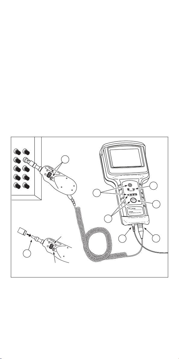
Features and Use
WCaution
Some adapter tips have small screws that slide into a
slot on the probe end. Do not adjust this screw.
1
2
5
3
6
Adapter tip
(match connector
to be inspected)
Focus
control
Magnification
control
4
7
2
aul01f.eps
FT600 Instruction Sheet / 03/18/08
English Page 3
AConnect the FT650 Fiber Probe to the display.
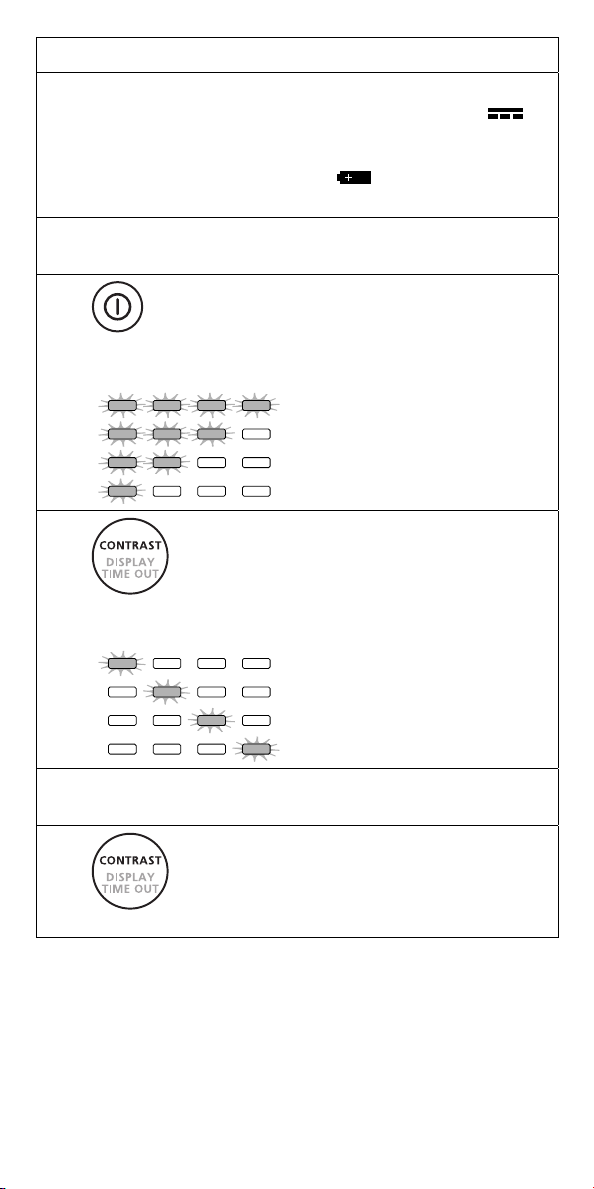
BTo ensure continuous operation, connect the ac
adapter whenever possible. The ac power LED ( )
lights when the ac adapter is connected. The LEDs
turn on from left to right as the battery approaches
full charge. The battery LED ( ) lights when the
display is using battery power.
CScrew an adapter tip onto the fiber probe to match
the connection you are inspecting.
Press the power key to turn on the display.
The LEDs indicate battery charge level for 5
seconds:
D
LEDs Battery Charge Level
75% - 100 %
50 % - 75 %
25 % - 50 %
1 % - 25 %
The power-down timer sets the time the
display stays on. To select a time, hold
down the contrast/timer key, then release
it when the desired LEDs light:
E
LEDs Power-down Timer
15 seconds
30 seconds
60 seconds
Timer disabled
FTurn the larger ring on the probe to focus the image.
Turn the smaller ring to change magnification.
G
Press the contrast/timer key briefly to
change the display contrast.

FT600 Instruction Sheet / 03/18/08
English Page 4
Registration
Registering your product with Fluke Networks gives you access
to valuable information on product updates, troubleshooting
tips, and other support services. To register, fill out the online
registration form on the Fluke Networks website at
www.flukenetworks.com/registration.
Contacting Fluke Networks
www.flukenetworks.com
+1-425-446-4519
•Australia: 61 (2) 8850-3333 or 61 (3) 9329 0244
•Beijing: 86 (10) 6512-3435
•Brazil: 11 3759 7600
•Canada: 1-800-363-5853
•Europe: +44-(0) 1923 281 300
•Hong Kong: 852 2721-3228
•Japan: 03-3434-0510
•Korea: 82 2 539-6311
•Singapore: +65-6799-5566
•Taiwan: (886) 2-227-83199
•USA: 1-800-283-5853
Visit our website for a complete list of phone numbers.
Maintenance
Clean the display with glass cleaner and a soft, lint-free cloth.
Clean the case with a soft cloth dampened with water or a mild
detergent. Do not use solvents or abrasive cleansers.
Replacing the Battery
Replace the lithium ion battery when its life becomes noticeably
shorter. To replace the battery, open the battery door on the
back of the display. Slide the battery up to remove it from the
battery contacts. Slide a new battery onto the contacts, then
replace the battery door.
Getting Service
Contact Fluke Networks for information on authorized Fluke
Networks service centers.

FT600 Instruction Sheet / 03/18/08
English Page 5
Accessories
The following accessories are available from Fluke Networks for
the FT600 FiberInspector Pro microscope.
Visit the Fluke Networks website at www.flukenetworks.com
for a complete list of fiber test equipment and accessories.
Description Fluke Model
TPak™meter hanging kit
(Lets you hang the display from a
strap or a magnet.)
TPAK
Fiber Optic Cleaning Kit NFC-Kit-Case
MT-RJ adapter tip NF360
LC adapter tip NF362
MU adapter tip NF364
AC adapter (100 V – 240 V) Contact Fluke Networks
LiIon battery pack Sony®type NP-550
Specifications
FT600 General Specifications
Temperature
range Operating: 0 °C to 40 °C
Storage: -10 °C to +60 °C
Humidity range Operating: 0 % to 45 % RH non-condensing;
Storage: 0 % to 95 % RH non-condensing
Certifications P
FT630 Fiber Display
Display type 3.5 in (9 cm) TFT, active matrix,
320 x 240 pixels
Video input NTSC
Power source Lithium ion battery or ac power
Battery life 2 hours continuous use
Dimensions 4 in x 2.1 in x 8.7 in
(10 cm x 5.3 cm x 22 cm)
Weight 0.8 lb (0.4 kg)

FT600 Instruction Sheet / 03/18/08
English Page 6
FT650 Fiber Probe
Magnification 250X and 400X
Camera type 0.33 in (8.38 mm) CCD with adjustable
focus
Light source LED
Power source From FT630
Lighting technique Coaxial
Dimensions 1.8 in x 1.7 in x 5.5 in
(45.7 mm x 43.2 mm x 140 mm)
(length depends on adapter tip)
Weight 0.4 lb (180 g)
LIMITED WARRANTY AND LIMITATION OF LIABILITY
Fluke Networks mainframe products will be free from defects in
material and workmanship for one year from the date of
purchase. Parts, accessories, product repairs and services are
warranted for 90 days, unless otherwise stated. Ni-Cad, Ni-MH
and Li-Ion batteries, cables or other peripherals are all
considered parts or accessories. This warranty does not cover
damage from accident, neglect, misuse, alteration,
contamination, or abnormal conditions of operation or
handling. Resellers are not authorized to extend any other
warranty on Fluke Networks’ behalf. To obtain service during
the warranty period, contact your nearest Fluke Networks
authorized service center to obtain return authorization
information, then send your defective product to that Service
Center with a description of the problem.
THIS WARRANTY IS YOUR ONLY REMEDY. NO OTHER
WARRANTIES, SUCH AS FITNESS FOR A PARTICULAR PURPOSE,
ARE EXPRESSED OR IMPLIED. FLUKE NETWORKS IS NOT LIABLE
FOR ANY SPECIAL, INDIRECT, INCIDENTAL OR CONSEQUENTIAL
DAMAGES OR LOSSES, ARISING FROM ANY CAUSE OR THEORY.
Since some states or countries do not allow the exclusion or
limitation of an implied warranty or of incidental or
consequential damages, this limitation of liability may not apply
to you.
Fluke Networks
PO Box 777
Everett, WA 98206-0777
USA
4/04
Table of contents
Other Fluke Microscope manuals


Popular Microscope manuals by other brands


VWR
VWR VisiScope 384 Series instruction manual

Nikon
Nikon ECLIPSE E200 POL instructions

Leica
Leica DI C800 User's manual & installation instructions

ThermoFisher Scientific
ThermoFisher Scientific Continuµm manual

ThermoFisher Scientific
ThermoFisher Scientific Continuµm manual

Olympus
Olympus SZ61 instructions