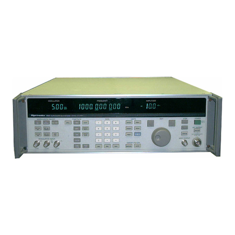
Fluke 6070A User manual


6070A/6071A
X


Section
1
Introduction
and
Specifications
1-1.
THE
6070A/6071A
INSTRUCTION
MANUAL
SET
1-2.
The
John
Fluke
Models
6070A
and
6071A
RF
Synthesized
Signal
Generators
are
documentated
by
a
set
of
four
manuals:
the
6070A/6071A
Operator
Manual,
the
6070A/6071A
Calibration
Manual,
the
6070A/6071A
Service
Manual,
and
the
6070A/607IA
Schematic
Manual
(Figure
1-1).
The
6070A/607iA
Operator
Manual
introduces
the
operator
to
the
instrument;
familiarizes
the
operator
with
all
instrument
controls,
connectors,
and
indicators;
and
presents
detailed
operating
information
and
procedures
for
both
manual
(local)
and
systems
(remote)
operation.
The
6070A/607IA
Calibration
Manual
provides
procedures
for
general
maintenance,
performance
checks,
and
calibration
adjustments.
The
6070A/6071A
Service
Manual
contains
a
description
of
the
theory
of
operation,
troubleshooting
procedures,
and
a
list
of
replaceable
parts.
The
6070A/6071A
Schematic
Manual
contains
schematic
digrams,
wire
lists,
interconnects
diagrams,
and
an
overall
basic
block
diagram
of
the
instrument.
1-3.
The
major
difference
between
the
two
models
is
that
the
6071A
has
twice
the
upper
frequency
limit
of
the
6070A.
Because
of
their
similarity,
most
of
the
text
in
this
manual
will
apply
to
both
models.
Text
that
applies
to
just
the
6070A
or
just
the
6071A
will
be
identified
as
such.
6070A/6071A
Operator
Manual
6070A/6071A
Calibration
Manual
6070A/6071A
Service
Manual
6070A/6071A
Schematic
Manual
Figure
1-1.
6070A/S071A
Instruction
Manual
Set

1-4.
THE
6070A/6071A
OPERATOR
MANUAL
.
.
.
,
.
1-5.
The
information
in
this,
the
6070A/6071A
Operator
Manual,
is
divided
into
7
sections:
1
INTRODUCTION
AND
Introduces
the
6070A/6071A
Instruction
s:PFr!FirAT10NS
Manual
Set
and
the
6070A
and
6071A
RF
Synthesized
Signal
Generators.
Lists
the
specifications
for
both
the
6070A
and
the
6071
A.
2
SHIPPING
AND
SERVICE
INFORMATION
3
INSTALLATION
AND
MAINTENANCE
4
FAMILIARIZATION
5
LOCAL
OPERATION
Describes
how
to
ship
the
instrument
and
how
to
get
problems
corrected.
Describes
how
to
physically
install
the
instrument
--
including
connecting
line
power
and
the
IEEE-488
interface
-
and
how
to
perform
operator
maintenance.
Describes
the
location
and
function
of
each
control,
connector,
indicator,
and
annunciator;
and
presents
an
exercise
to
familiarize
the
operator
with
the
instrument
(this
exercise
also
provides
a
gross
check
of
instrument
function).
Describes
manual
(front
panel)
operation
of
the
instrument.
6
REMOTE
OPERATION
(IEEE-488,
1978)
7
ACCESSORY
AND
OPTION
INFORMATION
Describes
system
operation
via
the
IEEE-
488
interface.
Describes
each
accessory
briefly
and
describes
the
capabilities
and
operation
of
each
option.
1-6
THE
6070A/6071A
SYNTHESIZED
RF
SIGNAL
GENERATOR
1-7.
The
John
Fluke
Models
6070A
and
6071A
Synthesized
RF
Signal
Generators
are
designed
for
use
in
the
calibration
laboratory,
engineering
laboratory,
or
manufacturing
environments.
Both
models
offer
extensive
modulation
capabilities
and
use
phase-locked
loop
circuitry
to
generate
fully
synthesized
signals
with
extremely
low
discrete
spurious,
and
phase
noise.
These
versatile
instruments
are
intended
for
both
bench
and
systems
use.
When
the
instrument
is
used
in
a
system,
all
front
panel
control
functions
(except
POWER
and
MOD
OUT
level)
can
be
controlled
via
an
iEEE-488,
1978,
interface.
1-8.
Instrument
parameters,
such
as
output
frequency
and
amplitude,
can
be
programmed
to
specific
values
or
manually
adjusted
using
the
Edit
Knob
(large
knob
near
the
lower
right
corner
of
the
front
panel).
The
Edit
Knob
is
connected
to
a
digital
rotary
encoder
to
provide
the
same
continuous
manual
adjustment
capability
analog
tuning
control
provides,
but
with
the
positive
positioning
of
a
digital
control.
I
he
rotary
encoder
has
25
magnetic
detent
positions.
The
user
can
feel
each
position
of
the
Edit
Knob.
1-9.
The
major
difference
between
the
two
models
is
that
the
6071A
has
twice
the
output
frequency
of
the
6070A.
The
output
frequency
of
the
6070A
can
be
selected
within
Hz

over
a
range
from
200
kHz
lo
519.999999
Mhz
(520
MHz).
The
output
frequency
of
the
6071A
can
be
selected
within
1
Hz
from
200
kHz
to
520
MHz
and
within
2
Hz
from
520
MHz
to
1039.999998
MHz
(1040
MHz).
Both
models
can
produce
frequencies
outside
of
the
specified
ranges,
but
the
performance
is
not
guaranteed.
1-10.
The
UNCAL
annunciator
will
turn
on
to
indicate
that
the
instrument
is
operating
beyond
specified
ranges.
The
synthesized
RF
signal
is
available
at
the
from
panel
RF
OUTPUT
connector
(if
the
607XA-830
Rear
Panel
Output
Option
is
installed,
the
RF
output
is
available
at
a
rear
panel
Type
N
connector).
1-11.
Internal
frequency
reference
is
a
10
MHz
free
air
timebase
(the
607XA-130
Oven
Reference
Option
is
available
for
increased
accuracy
and
stability).
This
10
MHz
reference
can
also
be
phase
locked
to
external
references
of
1,
2,
2.5,
5,
or
10
MHz(0.3
to
4V
peak-to-peak
sine
or
square
wave)
input
via
a
rear
panel
BNC
connector
(50
Ohm
input
impedance,
nominally).
When
an
external
reference
is
used,
the
shift
from
internal
to
external
is
automatic.
The
10
MHz
reference
signal
(used
as
the
internal
instrument
reference)
is
available
as
a
TTL
signal
at
a
rear
panel
REF
OUT
connector.
1-12.
Below
520
MHz,
output
level
can
be
selected
with
a
resolution
of
0.1
dB
over
the
range
of
+
19
to
-140
dBm
(2
V
to22nV
rms)inlo
50
Ohms.
At
520
MHz
or
above,
output
level
can
be
selected
with
a
resolution
of
0.1
dB
over
the
range
of+13
to
-140
dBm
(I
V
to
22
nV
rms).
Selected
level
is
displayed
on
the
front
panel
in
either
dBm
or
volts
(the
instrument
will
convert
from
one
to
the
other
if
the
units
are
changed).
The
internal
microprocessor
automatically
compensates
output
level
for
flatness
and
accuracy
although
this
automatic
correction
can
be
disabled
(special
function
81).
1-13.
The
RF
output
signal
can
be
modulated
in
various
combinations
of
amplitude
modulation
(AM),
frequency
modulation
(FM),
or
phase
modulation
(0M)
from
internal
sources,
external
sources,
or
a
combination
of
internal
and
external
sources.
Table
1-1
lists
all
modulation
combinations
and
the
possible
modulation
sources
for
each
combination.
Amplitude
modulation
depth
can
be
selected
with
a
resolution
of
0.1
%
over
the
range
of
0%
to
99.9%
(see
the
specifications
for
calibrated
range).
The
frequency
modulation
function
allows
the
output
frequency
to
be
deviated
while
the
output
frequency
is
still
synthesized
unless
the
DCFM
Mode
is
selected.
Maximum
index
of
modulation
that
can
be
selected
for
either
FM
or
0M
depends
upon
the
output
frequency
and
the
modulation
frequency
selected.
The
internal
modulation
signal
can
be
made
available
at
the
MOD
OUT
connectors
(front
and
rear
panels).
An
external
modulation
signal
can
be
either
ac
or
dc
coupled
through
parallel
connectors
on
the
rear
and
front
panels
(MOD
IN
connector,
600
Ohm
nominal
input
impedance).
External
input
sensitivity
is
such
that
a
1
V
peak
input
signal
produces
the
calibrated
modulation.
The
list
of
specifications
at
the
end
of
this
section
provides
detailed
information
about
the
modulation
characteristics.
1-14.
Up
to
9
front
panel
setups
can
be
stored
in
the
internal
memory
of
the
standard
instrument,
but
these
setups
are
lost
when
the
instrument
is
turned
off.
The
607XA-570
Non-Volatile
Memory
Option
provides
50
memory
locations.
Since
this
option
is
battery
powered,
front
panel
setups
stored
in
these
50
locations
are
not
lost
when
the
instrument
is
turned
off.
1-15.
Three
outputs
are
available
for
coordinating
the
activity
of
associated
devices:
sweep
analog
output,
penlift
output,
and
output
invalid
output.
The
sweep
analog
output
is
available
at
the
front
panel
SWP
OUT
connector.
This
output
steps
from
0
to
lOV
as
the
frequency
is
swept
from
the
start
frequency
to
the
stop
frequency.
The
size
of
the
steps
depends
upon
the
sweep
width
and
the
sweep
increment
selected.
The
penlift
output
is

available
at
a
rear
panel
BNC
connector.
This
output
is
a
TTL
signal
that
goes
high
during
a
sweep
retrace
and
stays
high
until
the
next
sweep
starts.
The
output
valid
signal
is
available
at
a
rear
panel
BNC
connector.
This
output
is
a
TTL
signal
that
goes
high
when
output
frequency,
output
amplitude,
or
modulation
is
potentially
unsettled.
1-16.
The
6070A
or
6071A
can
operate
from
line
voltages
either
between
90
to
132V
ac
or
between
180
to
264V
ac
at
any
frequency
from
47
to
63
Hz.
Section
3
of
this
manual
presents
a
procedure
for
switching
between
the
two
ranges
of
line
voltage.
Table
1-1.
Sources
for
Modulation
Combinations
COMBINATION
SOURCE
INTERNAL
EXTERNAL
AM
AM
AM
FM
FM
-.M
0M
0M
kJM
AM
+
FM
AM
FM
NONE
AM
FM
FM
AM
AM
+
0M
AM
0M
NONE
AM
0M
0M
AM
1-17.
OPTIONS
AND
ACCESSORIES
1-18.
The
options
and
accessories
available
for
use
with
the
6070A
and
the
6071A
are
listed
in
Table
1-2.
Additional
information
is
provided
in
the
Options
and
Accessories
section
of
this
manual.
1-19.
SPECIFICATIONS
1-20.
The
specifications
for
both
the
6070A
and
the
6071A
are
listed
in
Table
1-3.

Table
1-2.
6070A/6071A
Accessories
and
Options
MODEL/
OPTION
NO.
NAME
COMMENTS
ACCESSORIES
Y6001
Rack
Mount
Kit
Includes:
M05-205-600
(5Vi
inch
Rack
Mount
Ears)
and
MOO-280-610
(24-
inch
Rack
Slides).
Y8001
IEEE
Standard
Cable.
1
meter
Y8002
IEEE
Standard
Cable.
2
meters
Y8003
IEEE
Standard
Cable.
4
meters
Y9100
Attenuator.
6
dB
50
Ohm,
2W,
BNC
Y9101
Attenuator,
15
dB
50
Ohm,
2W,
BNC
Y9102
Attenuator,
20
dB
50
Ohm,
2W,
BNC
Y9103
50
Ohm
Feedthru
Termination.
BNC
Y9111
Coaxial
Cable.
50
Ohm.
3
feet
{0.91m),
BNC
Y9112
Coaxial
Cable,
50
Ohm,
6
feet
(1.83m),
BNC
Y9300
Directional
Coupler,
100
kHz
to
2
1.95
dB
Coupling.
0.5
dB
Insertion
GHz,
50
Ohm
Impedance,
BNC
Loss,
typically
30
dB
directivity
to
1
GHz.
Y9301
Min-loss
Pad.
DC
to
1
GHz.
50
Ohm
In
Better
than
1.2
to
1
VSWR,
not
more
-
75
Ohm
Out,
1
W.
BNC
than
6
dB
Insertion
loss.
Y9302
Attenuator.
3
dB
DC
to
1
GHz,
2W
average,
50
Ohm.
Y9303
Attenuator,
6
dB
1.25
VSWR
max..
Type
N
Y9304
Attenuator,
10
dB
Y9305
Attenuator.
20
dB
Y9306
Attenuator,
30
dB
Y9307
Adapter,
Type
N
Male
to
BNC
Female,
75
Ohm
impedance
Y9308
Adapter,
Type
N
Male
to
BNC
Female,
50
Ohm
Impedance
Y9309
Adapter,
Type
N
Male
to
Type
N
Male
Y9310
Adapter.
Type
N
Male
to
SMA
Female
Y9311
RF
Detector,
Broad
Crystal
Detector,
Total
Output
Flatness:
±0.6
dB
100
50
Ohm,
BNC
kHz
to
1.2
GHz,
positive
output.
Y9312
Double
Balanced
Mixer,
500
Hz
to
10
+7
dBm
LO.
conversion
loss
10
dB
MHz,
BNC
max.,
isolation
20
dB
min.
Y9313
Double
Balanced
Mixer,
2
MHz
to
1
17
dBm
LO,
conversion
loss
10
dB
GHz,
BNC
max.,
isolation
20
dB
min.
Y9314
Power
Splitter,
2
MHz
to
1
GHz,
BNC
Y9315
Coaxial
Cable,
50
Ohm.
Type
N
Male
Y9316
Cap,
Non-shorting,
BNC
Y9317
50
Ohm
Termination,
Shielded,
Type
N

6070A/6071A
Table
1-2.
6070A/6071A
Accessories
and
Options
(cont)
MODEL/
OPTION
NO.
NAME
COMMENTS
OPTIONS
607XA-130
Oven
Reference
High
stability
timebase
in
an
oven.
607XA-570
Non-Volatile
Memory
Battery
powered
memory.
Provides
50
storage
locations
for
front
panel
setups.
Retains
information
for
about
4
years.
607XA-830
Rear
Panel
RF
Output
Provides
the
6070A
RF
output
to
the
rear
panel
via
a
type
N
connector.
607XA-831
Auxiliary
RF
Output
Provides
a
portion
of
the
RF
output
at
a
rear
panel
BNC
connector.
This
signal
is
tapped
off
of
the
RF
output
signal
before
the
level
detector,
so
frequency
is
accurate,
but
level
is
not.
607XA-870
Reverse
Power
Protection
Provides
reverse
power
protection
for
(withstands
up
to
50
watts
protection
from
a
50
Ohm
source
over
the
frequency
range
of
200
kHz
to
1040
MHz
and
will
withstand
up
to
50V
dc).
1-6

Table
1-3.
6070A/6071A
Specifications
Unless
otherwise
noted,
the
following
performance
is
guaranteed
over
the
specified
environmental
an
AC
line
power
conditions
(see
GENERAL
at
the
end
of
this
table),
and
for
norma!
autoranging
operation,
20
minutes
after
the
instrument
is
turned
on.
FREQUENCY
Range
6070A.
.
0.2
to
519.999999
MHz.
6071A.
.
0.2
to
1039.999998
MHz.
Resolution
.
.
1
Hz
(2
Hz
above
520
MHz
for
the
6071A).
Accuracy
and
Stability.
.
Same
as
the
Reference
Oscillator.
Switching
Time.
.
The
time
from
when
the
signal
at
the
rear
panel
OUT
VALID
connector
goes
false
until
the
frequency
of
the
RF
output
signal
is
within
100
Hz
of
the
final
value
is
less
than
70
ms
(typically,
the
IEEE
and
instrument
processing
time
before
the
signal
at
OUT
VALID
goes
false
is
10
ms).
Connector
.
.
Type-N,
front
panel
RF
OUTPUT
connector.
50
Ohms
impedance,
nominal.
NOTE:
The
607XA-830
Rear
RF
Output
Option
makes
the
RF
output
signal
available
at
the
rear
pane!
instead
of
at
the
front
panel.
Specifications
for
options
are
listed
near
the
end
of
this
table.
REFERENCE
OSCILLATOR
Interna!
TYPE
.
.
Free-air,
10
MHz
crystal
oscillator.
AGING
RATE
.
.
<
±0.5
ppm/month
TEMPERATURE
STABILITY
..
.
±5
ppm
over
the
ambient
temperature
range
of
25“
C
±25“C
(77“F±45“F).
NOTE:
The
607XA-130
Oven
Reference
Oscillator
Option
provides
a
more
stable
internal
reference.
Specifications
of
options
are
listed
near
the
end
of
this
table.
External
CONNECTOR
.
.
BNC
rear
panel
REF
IN
connector.
Input
impedance
is
nominally
50
Ohms,
ac
coupled.
INPUT
SIGNAL
.
.
The
instrument
accepts
0.3
to
4.0V
peak-to-peak
sine
or
square
wave
at
1,
2,
2.5,
5,
or
10
MHz.
LOCK
RANGE
.
.
±8
ppm
frequency
difference.
Out-of-lock
is
indicated
by
the
FREQ
and
UNCAL
annuciators.
Reference
Output
.
.
10
MHz
(TTL)
available
at
the
rear
panel
REF
OUT
connector
(BNC).
AMPLITUDE
Specified
Range
.
.
+19
to
-140
below
520
MHz.
+13
to
-140
520
MHz
and
above.
NOTE:
AM
is
restricted
above
+/i
dBm
(+7
dBm
above
520
MHz)
and
below
-131
dBm.
Unspecified
Overrange
.
.
Up
to
+20.9
dBm
and
down
to
-150
dBm.
typically.
Resolution
.
.
0.1
dB
(at
least
1%
when
displaying
voltage).

Table
1-3.
6070A/6071A
Specifications
(cont)
Switching
Time
The
time
from
when
the
signal
at
the
rear
pane!
OUT
VALID
connector
goes
false
until
the
amplitude
of
the
RF
output
signal
is
within
0.1
dBofthefinal
value
is
less
than
10
ms
{typically,
the
IEEE
and
instrument
processing
time
before
the
signal
at
OUT
VALID
goes
false
is
IQ
ms
for
voltage
and
40
ms
for
dB
programming).
Accuracy
and
Flatness
RF
OUTPUT
ACCURACY
(dB)“
FREQUENCY
(MHz)
LEVEL
(dBm)*
0.2
to
520
MHz
{6070A
and
6071
A)
+19
to
+13
+13
to
-131
-131
to
-140
±1.5
±[0.8
-
0.01
(output
level
in
dBm)]
±4.0
520
to
1040
MHz
(6071A
only)
+13
to
+7
+7
to
-131
-131
to
-140
±2.5
±[1.6
-
0.015
(output
level
in
dBm)]
±4.5
“Add
±0.5
dB
to
the
accuracy
specification
if
the
607XA-870
Reverse
Power
Protection
Option
is
installed.
Source
SWR
(reference
to
50
Ohms)
Less
than
the
values
listed
in
the
following
table.
LEVEL
(dBm)
SOURCE
SWR
0.2
TO
520
MHz
520
TO
1040
MHz
>i-7
2.0
2.5
<+7
1.5
2.0
SPECTRAL
PURITY
Spurious
.
Spurs
are
below
the
values
listed
in
the
following
table
or
-140
dBm,
whichever
is
greater
(or
-130
dBm
at
520
MHz
if
the
607XA-870
Reverse
Power
Protection
Option
is
installed).
SPECTRAL
PURITY
(dBc)
SPURIOUS
SIGNALS
RF
OUTPUT
FREQUENCY
(MHz)
0.2
TO
62.5
TO
125
TO
250
TO
520
TO
62.5
125
250
520
1040
Non-harmonic
-84
>10
kHz
offset*
-90
-100
-96
-90
<10
kHz
offset
-70
-82
-76
-70
-64
<0.55
kHz
offset
-56
-68
-62
-56
-50
Sub-harmonic
N/A
-35
(1/2,
3f/2,
5f/2.
etc.)
Harmonic
6070A
>+13
dBm
-35
-35
-35
-30
N/A
<+13
dBm
-35
-35
-35
-35
Harmonic
6071A
>+13
dBm
-35
-35
-30
-25
N/A
<+13
dBm
-35
-35
-35
-35
-25
‘Spurs
are
5
dB
worse
during
HI
DEV
Mode
operation.

SSB
PHASE
NOISE
IN
1
Hz
BANDWIDTH
(dBc)
6070A/6071A
Table
1-3.
6070A/6071A
Specifications
(cont)
Noise
Spectral
Density
.
T
he
SSB
phase
noise
densit>
The
SSB
phase
noise
density
is
a
function
of
offset
and
output
frequency.
The
following
performance
is
guaranteed
when
not
in
the
HI
DEV
Mode
and
includes
the
effect
of
the
internal
reference.
NOISE
SPECTRAL
DENSITY
(dBc/Hz)
OFFSET
FROM
CARRIER
0.1
kHz
1
kHz
5
kHz
20
kHz
■
>3
MHz
-75
-85
-107
-123
:
-129
-94
-100
-125
-140
-144
-88
-94
-121
-138
-144
-82
-88
-115
-132
-144
-76
-82
-109
-126
-138
FREQUENCY
(MHz)
0.2
to
62.5
62.5
to
125
125
to
250
250
to
520
520
to
1040
Signal-to-Phase
Noise
Ratio
vs.
Offset
Frequency
from
Carrier
at
80,
320,
and
500
MHz.
(Typical)
▼
Guaranteed
at
500
MHz
MHz
»80
^
-’
‘-82-
--
OFFSET
FROM
CARRIER
(Hz)

SSB
PHASE
NOISE
IN
1
Hz
BANDWIDTH
(dBc)
co
SSB
PHASE
NOISE
IN
1Hz
BANDWIDTH
(dBc)
6070A/6071A
Table
1-3.
6070A/6071A
Specifications
(cont)
Signa!-to-Phase
Noise
Ratio
vs.
Carrier
Frequency
for
20
kHz
Offset
from
Carrier
and
Broadband
Noise
Floor
(^3
MHz
Offset).
-120
■
130
-140
-150
-123^
-126
Guaranteed
-129
2
p-T'7
)
kHz
Offsets
-132—
1
_J_L
Typical
-140
-138
-143
^4^
-150
E
iroadba
Id
Nois
e
Floor,
Typica
0.2
62.5
125
250
520
CARRIER
FREQUENCY
(MHz)
1040
ignal-to-Phase
Noise
Ratio
vs.
Offset
Frequency
from
Carrier
at
320
MHz
in
Hi
DEV
Mode
(Typical).
Residual
PM
(Hz
rms).
The
follov/ing
table
lists
the
residua!
FM
for
CW
(and
low
deviation
ACFM
and
OM).
FREQUENCY
(MHz)
RESIDUAL
FM
(Hz
rms)
0.3
TO
3
kHz
BW
0.05
TO
15
kHz
BW
HI
DEV
OFF
HI
DEV
ON
HI
DEV
OFF
HI
DEV
ON
.2
to
62.5
3.5
20
5
35
62.5
to
125
0.5
5
0.75
9
125
to
250
0.85
10
1.3
18
250
to
520
1.7
20
2.5
35
520
to
1040
3-4
40
5
70
[•1

Table
1-3.
6070A/6071A
Specifications
(cont)
Residual
AM
<0.02%
rms
in
a
50
Hz
to
15
kHz
post
detection
bandwidth
on
all
bands.
AMPLITUDE
MODULATION
Depth.0
to
99.9%
In
0.1%
steps
where
the
total
output
level
(amplitude
combined
with
AM)
does
not
exceed
4-19
dBm
peak
at
RF
output
frequencies
below
520
MHz
or
exceed
+13
dBm
peak
for
RF
output
frequencies
above
520
MHz.
Accuracy
.±5%
of
full
scale
above
5
MHz
or
+5%
to
-8%
of
full
scale
below
5
MHz
for
rates
shown
in
the
Distortion
specifications
that
follow.
Amplitude
accuracy
is
not
specified
below
-131
dBm.
Distortion
(internal
or
external)
FREQUENCY
DEPTH
FOR
SPECIFIED
ACCURACY
DISTORTION
(MHz)
0
TO
30%
AM
30
TO
70%
AM
70
TO
90%
AM
0.2
to
5
^1
kHz
<90%
<2%
<5%
<7%
5
to
520
^
kHz
<90%
<1.5%
<3%
<3%
520
to
1040
^
kHz
<70%
<2%
<3%
<5%
Bandwidth,
3
dB
.
a
t
90%
AM
for
RF
output
frequencies
between
5
MHz
and
520
MHz
or
at
70%
AM
for
RF
output
frequencies
below
5
MHz
and
above
520
MHz.
FREQUENCY
(MHz)
DC
COUPLED
AC
COUPLED
0.2
to
5
0
to
8
kHz
20
Hz
to
8
kHz
5
to
1040
0
to
50
kHz
20
Hz
to
50
kHz
incidental
FM
.<0.2
fm
for
30%
AM
(<0.6
fm
above
520
MHz
for
6071A),
where
fm
is
modulation
frequency,
at
the
rates
listed
in
the
Distortion
specifications.
FREQUENCY
MODULATION
Deviation
Ranges
FREQUENCY
(MHz)
DEVIATION
RANGES
(kHz)
H!
DEV
MODE
OFF
HI
DEV
MODE
ON
0.2
to
62.5
10,
20,
50,
100,
200
50.
100,
200,
500,
1000
62.5
to
125
2,
5.
10,
20,
50
10,
20,
50,
100,
200
125
to
250
5,
10,
20,
50,
100
20,
50,
100,
200,
500
250
to
520
10,
20,
50,
100,
200
50,
100,
200,
500,
1000
520
to
1040
20.
50,
100,
200,
500-
100,
200,
500,
1000
*Ht
DEV-
MODE
ON
if
deviation
>400
kHz,
100
Hz
up
to
99.9
kHz
Dev
1
kHz
above
99.9
kHz
Dev
Resolution

Table
1-3.
6070A/6071A
Specifications
(cont)
Maximum
Deviation
MAXIMUM
DEVIATION
(kHz)
FREQUENCY
(MHz)
ACFM
DCFM
THE
LESSER
OF:
THE
LESSER
OF:
0.2
to
62.5*
999
or
fm(520
-
fo)
499
kHz
62.5
to
125
199
or
fmfo
fo
or
99.9
125
to
250
499
or
fmfo
fo
or
199
250
to
520
999
or
fmfo
fo
or
499
520
to
1040
999
or
fmfo
fo
or
999
Where:
fm
=
the
numeric
value
of
modulation
frequency
expressed
in
kHz.
fo
=
the
numeric
value
of
the
RF
output
frequency
in
MHz.
*At
low
RF
output
frequencies,
the
sum
of
the
modulation
frequency
and
the
deviation
should
not
exceed
lOOOffo
-
0.2)
-
fm.
Minimum
Deviation
.10%
of
range
except
for
2,
20,
and
200
kHz
ranges
12.5%
of
range
for
2,
20,
and
200
kHz
ranges.
Deviation
Accuracy
(internal
or
externa!,
AC
or
DC)
AT
400
AND
1000
Hz
H!
DEV
Off.
±(10%
+
0.125%
of
range)
HI
DEV
On
.
±{7%
+
0.125%
of
range)
FROM
0.3
TO
50
kHz
(H!
DEV
on
or
off.
DCFM
on
or
off)
..
±(12%
+
0.125%
of
range)
Distortion
.The
total
harmonic
distortion
on
internal
or
on
external
sources
up
to
a
50
kHz
rate
is
a
function
of
output
frequency
and
mode,
and
is
less
than
the
values
listed
in
the
following
table.
FREQUENCY
(MHz)
DISTORTION
(%THD)
HI
DEV
OFF
HI
DEV
ON
0.2
to
62.5
0.5
+
0.75/100
kHz
DEV
1.5
62.5
to
125
0.5
+
3/100
kHz
DEV
1.5
125
to
250
0.5
+
1.5/100
kHz
DEV
1.5
250
to
520
0.5
+
0.75/100
kHzDEV
1.5
520
to
1040
0.5
+
0.375/100
kHz
DEV
1.5
NOTE:
Distonion
for
the
DCFM
Mode
is
0.5%
plus
1.2%
per
100
kHz
DEV
below
62.5
MHz
or
(600!fo)%per
lOOkHz
DEVabove62.5
MHz.
The
specification
applies
at
the
ambient
temperature
at
which
DCFM
is
enabled,
where
fo
is
the
RF
output
frequency
in
MHz.
Bandwidth
.
The
frequency
where
the
response
is
3
dB
below
the
maximum
is
at
least
250
kHz
at
the
high
end
and
less
than
20
Hz
at
the
low
end
when
AC
coupled.
Incidental
AM
.
<0.5%
AM
for
up
to
50
kHz
deviation
at
a
1
kHz
rate.

Table
1-3.
6070A/6071A
Specifications
(cont)
Center
Frequency
Accuracy
.
S
ame
as
the
reference
oscillator
for
ACFM.
The
center
frequency
accuracy
values
are
listed
in
the
following
table
for
the
DCFM
Mode
{after
enabling
DCFM).
FREQUENCY
(MHz)
MAXIMUM
INITIAL
TYPICAL
FREQUENCY
OFFSET
(Hz)
STABILITY
(Hz/MINUTE)
0.2
to
62.5
±1000
50
62.5
to
125
±250
12.5
125
to
250
±500
25
250
to
520
±1000
50
520
to
1040
±2000
100
PHASE
MODULATION
Index
Ranges
FREQUENCY
(MHz)
INDEX
RANGES
(RADIANS)
HI
DEV
OFF
HI
DEV
ON
0.2
to
62.5
62.5
to
125
125
to
250
250
to
520
520
to
1040
1.
2,
5,
10.
20
0.2,
0.5.
1,
2,
5
0.5,
1,
2.
5,
10
1.
2.
5,
10.
20
2,
5.
10.
20,
50*
5,
10,
20.
50,
100
1,
2,
5,
10,
20
2.
5.
10,
20.
50
5.
10,
20,
50.
100
10,
20,
50,
100
•HI
DEV
Mode
if
index
>
40
Radians.
Resolution
.0.01
radian
up
to
9.99
radian.
0.1
radian
above
99.9
radian.
Maximum
Index
.Same
as
the
highest
available
range.
Minimum
Index
.
1
0%
of
range
except
for
0.2,
2,
and
20
radian
ranges
12.5%
of
range
for
0.2,
2,
and
20
radian
ranges.
Index
Accuracy
(internal
or
external)
AT
400
AND
1000
Hz
HI
DEV
Off.±(10%
+
0.125%
of
range)
HI
DEV
On
.±(7%
+
0.125%
of
range)
FROM
0.3
TO
3
kHz
(H!
DEV
ON
OR
OFF)
.
±(12%
+
0.125%
Of
range)
Distortion
.
T
he
total
harmonic
distortion
is
less
than
the
values
in
the
following
table.
Distortion
.
T
he
total
harmonic
distortion
is
less
than
the
values
in
the
following
table.
FREQUENCY
(MHz)
HI
DEV
OFF
HI
DEV
ON
0.2
to
62.5
0.5%
+
(0.75
x
10-nm)%
per
Rad
1.5%
62.5
to
125
0.5%
+
(3.0
X
10-^m)%
per
Rad
1.5%
125
to
250
0.5%
±
(1.5
X
10-'^m)%
per
Rad
1.5%
250
to
520
0.5%
+
(0.75
X
10-®fm)%
per
Rad
1.5%
520
to
1040
0.5%
+
(0.37
X
10-‘fm)%
per
Rad
1.5%
Where
fm
is
the
numerical
value
of
the
modulation
frequency
in
Hz.

Table
1-3.
6070A/6071A
Specifications
(cont)
Bandwidth
.
The
frequency
where
the
response
is
3
dB
beiow
the
maximum
is
at
least
12
kHz
at
the
high
end
and
less
than
20
Hz
(ac
coupled)
or
dc
(dc
coupled)
at
the
low
end.
Incidental
AM
.
<0.5%
AM
for
deviations
up
to
50
radians
at
1
kHz
rate
EXTERNAL
MODULATION
INPUT
Connector
.
Front
and
rear
panel
MOD
IN
connectors
(BNC),
connected
in
parallel,
with
a
nominal
600
Ohm
input
impedance.
External
Input
Sensitivity
.
IV
peak
provides
the
programmed
modulation
depth.
INTERNAL
MODULATION
OSCILLATOR
Frequency
Ranges
.
20
Hz
to
199
Hz
200
Hz
to
1.990
kHz
2
kHz
to
19.9
kHz
20
kHz
to
199
kHz
Unspecified
Overrange.
Down
to
1
Hz
and
up
to
255
kHz.
Frequency
Accuracy
.
±3%
over
the
range
20
to
30°C
(68
to
86°F).
±(3%
+
0
.
1
%/°C)below
20
and
above
30°C.
Distortion
.
<0.15%
THD
from
0.2
to
100
kHz
<0.2%
THD
below
0.2
kHz
and
above
100
kHz.
Output
.
Front
panel
MOD
OUT
connector
(BNC)
and
associated
level
control
provide
nominally
0
to
1
volt
peak
into
600
Ohms.
Level
is
not
programmable.
Output
impedance
is
600
Ohms,
nominal.
OTHER
OUTPUTS
Sweep
Analog
Output
.
Front
panel
SWP
OUT
connector
(BNC)
provides
0
to
10V
up
to
a
1000
point
stepped
ramp.
Accuracy
of
the
output
is
±5%
of
output
±0.1V.
PeniifI
.
Rear
panel
PEN
LIFT
connector
(BNC)
provides
a
TTL
signal
which
is
high
during
sweep
retrace
and
until
the
next
sweep
starts.
Output
Valid
.
Rear
pane!
OUT
VALID
connector
(BNC)
provides
a
TTL
signal
which
is
low
when
the
RF
output
is
potentially
unsettled.
This
signal
is
also
available
on
the
IEEE
interface.

Table
1-3.
6070A/6071A
Specifications
(cont)
MEMORY
Memory
Functions.
Store,
recall,
insert
above,
delete,
define
top.
Number
of
Locations
.
9
standard,
volatile
(contents
are
lost
when
power
is
removed);
50
with
the
607XAA-570
Non-Volatile
Memory
Option
(contents
are
retained
for
about
4
years
after
power
is
removed),
Front
panel
setups
can
be
stored
in
each
location
and
later
recalled.
FREQUENCY
SWEEP
Sweep
Modes
.
Auto,
(repetitive),
single,
manual.
Sweep
Functions
.
Symmetrical
sweep,
asummetrical
sweep,
sweep
speed.
Data
Entry
Parameters
.
Sweep
width
and
sweep
increment.
Sweep
Speed.
When
slow
sweep
speed
is
not
selected,
the
instrument
will
sweep
frequency
as
fast
as
possible
without
regard
to
whether
or
not
the
frequency
is
settled.
When
slow
sweep
speed
is
selected,
the
settled
period
of
each
increment
can
be
set
to
20
ms,
50
ms,
100
ms,
200
ms.
and
500
ms.
Sweep
Output
.
Oto
+10V,
up
to
1000-point
stepped
ramp.
Available
at
the
front
panel
SWP
OUT
connector.
Penlitt/Z
Axis
Blanking
Output
...
TTL
level
at
the
rear
panel
PEN
LIFT
connector.
High
during
sweep
retrace
and
until
the
next
sweep
starts.
REMOTE
CONTROL
interface
.
IEEE
Standard
488,
1978.
Functions
Controlled
.
Ait
front
panel
controls
except
the
POWER
and
MOD
OUT
controls.
Status
indicators
.
REM
(remote),
ADDR
(addressed),
SRQ.
interface
Functions
.
SH1.
AHI,
T6.
TEO,
L3,
LEO,
SRI,
RL1,
PPO,
DC1,
DTI,
CD.
GENERAL
Temperature
OPERATING
.
NON-OPERATING.
0
to
50°C
(32
to
122®F)
.
-40
to
75“
C
(-40
to
167°
F)
Operating
Humidity.
.
0
to
95%
up
to
25°
C
(77°
F)
Oto
75%
up
to
50°C
(122°
F)

Table
1-3.
6070A/6071A
Specifications
(cont)
Conducted
and
Radiated
Interference
.
<3
uV
induced
in
a
2
turn,
1-inch
loop
that
is
1
inch
from
any
surface
and
measured
into
a
50
Ohms
receiver.
Complies
with
RE02
and
CEOS
of
MIL-
STD-461A,
sections
4.3.1
and
4.3.2
of
MIL-1-6181D.
both
narrow
and
broad
band.
Size
.
width
height
depth
43
cm
13.3
cm
54.6
cm
17
inches
5.25
inches
21.5
inches
Weight
.
28
kg
(61
lbs.)
Power
.
100.
120,
200,
and
240V
ac
±10%,
47
to
63
Hz.
Protection
Class
.
OPTIONS
Class
1
(as
defined
in
lEC
348)
607XA-130
Oven
Reference
Option
FREQUENCY
.
10
MHz
AGING
RATE
.
<±5
X
10-’°/day,
after
a
21
day
warmup.
TEMPERATURE
STABILiTY
....
<±2
X
10-’V°C.
POWER
.
607XA-570
Non-Voiatiie
Memory
Option
On
during
standby
operation
(STBY
indicator
on).
NUMBER
OF
LOCATIONS.
50
STORAGE
TIME.
With
power
removed,
the
contents
will
be
retained
for
about
4
years.
POWER
SOURCE
.
Instrument
power
supply,
operating
or
in
standby.
Battery
when
power
is
removed.
POWER-ON
CONDITION
.
607XA-830
Rear
RF
Output
Option
(replaces
the
front
panel
RF
OUTPUT
connector)
Instruments
with
this
option
return
the
front
panel
to
the
setup
that
existed
when
the
instrument
was
placed
in
standby
or
was
turned
off.
SPECIFICATIONS
.
.
Same
as
standard
instrument.
CONNECTOR
..
.
Type
N,
rear
panel
RF
OUT
connector.
607XA-831
Auxiliary
RF
Output
upnon
FREQUENCY
.
.
Same
as
RF
output
frequency.
AMPLITUDE
.
>-18
dBm
for
normal
autoranging
operation.
IMPEDANCE
.
.
50
Ohms,
nominal.
CONNECTOR
.
.
BNC,
rear
panel
AUX
OUT
connector.
This manual suits for next models
1
Table of contents
Other Fluke Portable Generator manuals
Fluke
Fluke 5128A User manual
Fluke
Fluke PM 5136 Instruction manual

Fluke
Fluke Wavetek-Datron 395 Instruction Manual

Fluke
Fluke 281 User manual

Fluke
Fluke PM5418 User manual

Fluke
Fluke 291 User manual
Fluke
Fluke SimpliFiber Pro User manual
Fluke
Fluke 6080A User manual

Fluke
Fluke PM5414V User manual

Fluke
Fluke 291 Parts list manual
Popular Portable Generator manuals by other brands

Westerbeke
Westerbeke 25.0BTDAR 60HERTZ Operation and maintenance manual

BOLIY
BOLIY PRO3600SI owner's manual

Truper
Truper GEN-100X manual

Kipor
Kipor Sinamaster I G2600 Operation manual

ITW
ITW SIMCO-ION D165 Installation and operating instructions

Generac Portable Products
Generac Portable Products 4000XL 9777-2 owner's manual