Fluke 281 Parts list manual

®
281, 282, 284
40 MS/s Arbitrary Waveform Generators
Getting Started Manual
PN 2423304
January 2005
© 2005 Fluke Corporation, All rights reserved. Printed in USA
All product names are trademarks of their respective companies.

LIMITED WARRANTY AND LIMITATION OF LIABILITY
Each Fluke product is warranted to be free from defects in material and workmanship under normal use and service. The warranty period is one year and begins
on the date of shipment. Parts, product repairs, and services are warranted for 90 days. This warranty extends only to the original buyer or end-user customer of
a Fluke authorized reseller, and does not apply to fuses, disposable batteries, or to any product which, in Fluke's opinion, has been misused, altered, neglected,
contaminated, or damaged by accident or abnormal conditions of operation or handling. Fluke warrants that software will operate substantially in accordance
with its functional specifications for 90 days and that it has been properly recorded on non-defective media. Fluke does not warrant that software will be error free
or operate without interruption.
Fluke authorized resellers shall extend this warranty on new and unused products to end-user customers only but have no authority to extend a greater or differ-
ent warranty on behalf of Fluke. Warranty support is available only if product is purchased through a Fluke authorized sales outlet or Buyer has paid the applica-
ble international price. Fluke reserves the right to invoice Buyer for importation costs of repair/replacement parts when product purchased in one country is sub-
mitted for repair in another country.
Fluke's warranty obligation is limited, at Fluke's option, to refund of the purchase price, free of charge repair, or replacement of a defective product which is
returned to a Fluke authorized service center within the warranty period.
To obtain warranty service, contact your nearest Fluke authorized service center to obtain return authorization information, then send the product to that service
center, with a description of the difficulty, postage and insurance prepaid (FOB Destination). Fluke assumes no risk for damage in transit. Following warranty
repair, the product will be returned to Buyer, transportation prepaid (FOB Destination). If Fluke determines that failure was caused by neglect, misuse, contami-
nation, alteration, accident, or abnormal condition of operation or handling, including overvoltage failures caused by use outside the product’s specified rating, or
normal wear and tear of mechanical components, Fluke will provide an estimate of repair costs and obtain authorization before commencing the work. Following
repair, the product will be returned to the Buyer transportation prepaid and the Buyer will be billed for the repair and return transportation charges (FOB Shipping
Point).
THIS WARRANTY IS BUYER'S SOLE AND EXCLUSIVE REMEDY AND IS IN LIEU OF ALL OTHER WARRANTIES, EXPRESS OR IMPLIED, INCLUDING
BUT NOT LIMITED TO ANY IMPLIED WARRANTY OF MERCHANTABILITY OR FITNESS FOR A PARTICULAR PURPOSE. FLUKE SHALL NOT BE LIABLE
FOR ANY SPECIAL, INDIRECT, INCIDENTAL, OR CONSEQUENTIAL DAMAGES OR LOSSES, INCLUDING LOSS OF DATA, ARISING FROM ANY CAUSE
OR THEORY.
Since some countries or states do not allow limitation of the term of an implied warranty, or exclusion or limitation of incidental or consequential damages, the
limitations and exclusions of this warranty may not apply to every buyer. If any provision of this Warranty is held invalid or unenforceable by a court or other
decision-maker of competent jurisdiction, such holding will not affect the validity or enforceability of any other provision.
Fluke Corporation
P.O. Box 9090,
Everett, WA 98206-9090,
U.S.A.
Fluke Europe B.V.
P.O. Box 1186,
5602 BD Eindhoven,
The Netherlands
11/99 To register your product online, visit register.fluke.com
Safety
This generator is a Safety Class I instrument according to IEC classification and has been designed to meet the require-
ments of EN61010-1 (Safety Requirements for Electrical Equipment for Measurement, Control and Laboratory Use). It is an
Installation Category II instrument intended for operation from a normal single phase supply.
This instrument has been tested in accordance with EN61010-1 and has been supplied in a safe condition. This instruction
manual contains some information and warnings which have to be followed by the user to ensure safe operation and to retain
the instrument in a safe condition.
This instrument has been designed for indoor use in a Pollution Degree 2 environment in the temperature range 5 °C to
40 °C, 20 % - 80 % RH (non-condensing). It may occasionally be subjected to temperatures between +5 °C and -10 °C with-
out degradation of its safety. Do not operate the instrument while condensation is present.
Use of this instrument in a manner not specified by these instructions may impair the safety protection provided. Do not op-
erate the instrument outside its rated supply voltages or environmental range.
Warning
To avoid the possibility of electric shock:
• This instrument must be earthed.
• Any interruption of the mains earth conductor inside or outside the instrument will make the instrument
dangerous. Intentional interruption is prohibited. The protective action must not be negated by the use
of an extension cord without a protective conductor.
• When the instrument is connected to its supply, terminals may be live and opening the covers or re-
moval of parts (except those to which access can be gained by hand) is likely to expose live parts.
i

281, 282, 284
Getting Started Manual
• Any adjustment, maintenance and repair of the opened instrument under voltage shall be avoided as
far as possible and, if inevitable, shall be carried out only by a skilled person who is aware of the haz-
ard involved.
• Make sure that only fuses with the required rated current and of the specified type are used for re-
placement. The use of makeshift fuses and the short-circuiting of fuse holders is prohibited.
Caution
If the instrument is clearly defective, has been subject to mechanical damage, excessive moisture or
chemical corrosion the safety protection may be impaired and the apparatus should be withdrawn from use
and returned for checking and repair.
Note
This instrument uses a Lithium button cell for non-volatile memory battery back-up. Typical battery life is 5 years. In
the event of replacement becoming necessary, replace only with a cell of the correct type, a 3 V Li/Mn02 20 mm
button cell type 2032. Do not mix with solid waste stream. Do not cut open, incinerate, expose to temperatures
above 60 °C or attempt to recharge. Used batteries should be disposed of by a qualified recycler or hazardous ma-
terials handler. Contact your authorized Fluke Service Center for recycling information.
Caution
Do not wet the instrument when cleaning it and in particular use only a soft dry cloth to clean the LCD win-
dow.
ii

Safety (continued)
The following symbols are used on the instrument and in this manual:
Caution - refer to the accompanying documentation, incorrect operation may damage the instrument.
Terminal connected to chassis ground.
Mains supply OFF.
Mains supply ON.
Alternating current.
Warning - hazardous voltages may be present.
iii


EMC Compliance
This instrument meets the requirements of the EMC Directive 89/336/EEC.
Compliance was demonstrated by meeting the test limits of the following standards:
Emissions
EN61326 (1998) EMC product standard for Electrical Equipment for Measurement, Control and Laboratory Use. Test limits
used were:
a) Radiated: Class B
b) Conducted: Class B
c) Harmonics:EN61000-3-2 (2000) Class A The instrument is Class A by product category.
Immunity
EN61326 (1998) EMC product standard for Electrical Equipment for Measurement, Control and Laboratory Use. Test meth-
ods, limits and performance achieved were:
a) EN61000-4-2 (1995) Electrostatic Discharge: 4 kV air, 4 kV contact Performance A.
b) EN61000-4-3 (1997) Electromagnetic Field: 3 V/m, 80 % AM at 1 kHz Performance A.
c) EN61000-4-11 (1994) Voltage Interrupt: 1 cycle, 100 % Performance A.
d) EN61000-4-4 (1995) Fast Transient: 1 kV peak (ac line), 0.5 kV peak
(signal lines and RS232/GPIB ports)
Performance A.
e) EN61000-4-5 (1995) Surge: 0.5 kV (line to line), 1 kV (line to ground) Performance A.
v

281, 282, 284
Getting Started Manual
f) EN61000-4-6 (1996) Conducted RF: 3 V, 80 % AM at 1kHz
(ac line only; signal connections <3 m not tested)
Performance A.
According to EN61326 the definitions of performance criteria are:
Performance criterion A: ‘During test normal performance within the specification limits.’
Performance criterion B: ‘During test, temporary degradation, or loss of function or performance which is self-recovering’.
Performance criterion C: ‘During test, temporary degradation, or loss of function or performance which requires operator
intervention or system reset occurs.’
Caution
To ensure continued compliance with the EMC directive the following precautions should be observed:
a) connect the generator to other equipment using only high quality, double-screened cables.
b) after opening the case for any reason ensure that all signal and ground connections are remade cor-
rectly before replacing the cover. Always ensure all case screws are correctly refitted and tightened.
c) In the event of part replacement becoming necessary, only use components of an identical type. Refer
to the Service Manual.
vi

Table of Contents
Title Page
Introduction .................................................................................................................... 1
Before you Start ............................................................................................................. 1
Mains Supply Voltage................................................................................................ 1
Externally Applied Voltages....................................................................................... 1
Controls and Connections.............................................................................................. 2
Model 281 Front Panel .............................................................................................. 3
Principal Controls and Connectors............................................................................ 4
The Liquid Crystal Display Panel.......................................................................... 10
Multi-Channel Instruments - Front Panel Differences................................................ 10
Using the Instrument...................................................................................................... 12
Starting up................................................................................................................. 12
Generating Sine Waves............................................................................................. 13
Generating a Swept Output....................................................................................... 17
Other Standard Waveforms....................................................................................... 17
Triggered Modes ....................................................................................................... 19
Using the Synchronization Output............................................................................. 21
Tone Mode ................................................................................................................ 22
vii

281, 282, 284
Getting Started Manual
Arbitrary Waveforms ................................................................................................. 24
Other Functions............................................................................................................. 28
viii

Getting Started
Introduction
This Getting Started Manual for the model 281, 282 and
284 Arbitrary Waveform Generators is designed to
provide an initial understanding of the way the
instruments are operated. The manual is set out in the
form of a tutorial, guiding you through a series of basic
front panel operations in order to familiarize you with the
controls and the modes of operation.
The Users Manual contains detailed specifications and
descriptions of all the functions and operations accessible
both from the front panel and by means of the remote
interfaces.
Before you Start
Mains Supply Voltage
Check that the instrument operating voltage marked on
the rear panel is correct for the local supply. If it is
necessary to change the operating voltage, follow the
procedure described in appendix A of the Users Manual.
Externally Applied Voltages
Caution
To avoid risk of damage to the instrument,
do not apply external voltages to the
SYNC OUT or MAIN OUT sockets.
1

281, 282, 284
Getting Started Manual
Caution
To avoid risk of damage to the instrument, do
not apply external voltages exceeding ±10 V
to the TRIG IN, MODULATION or SUM inputs.
Controls and Connections
This section is designed to familiarize you with the 40
MS/s Arbitrary Waveform Generators' basic controls and
connectors. There are three versions of the instrument,
models 281, 282 and 284 being single-, 2- and 4-channel
versions respectively.
The Users Manual covers all three instruments. For this
Getting Started Manual we refer to the model 281 single-
channel instrument, except where multi-channel
operations are considered.
2

Getting Started
Controls and Connections
Model 281 Front Panel
shy0001f.gif
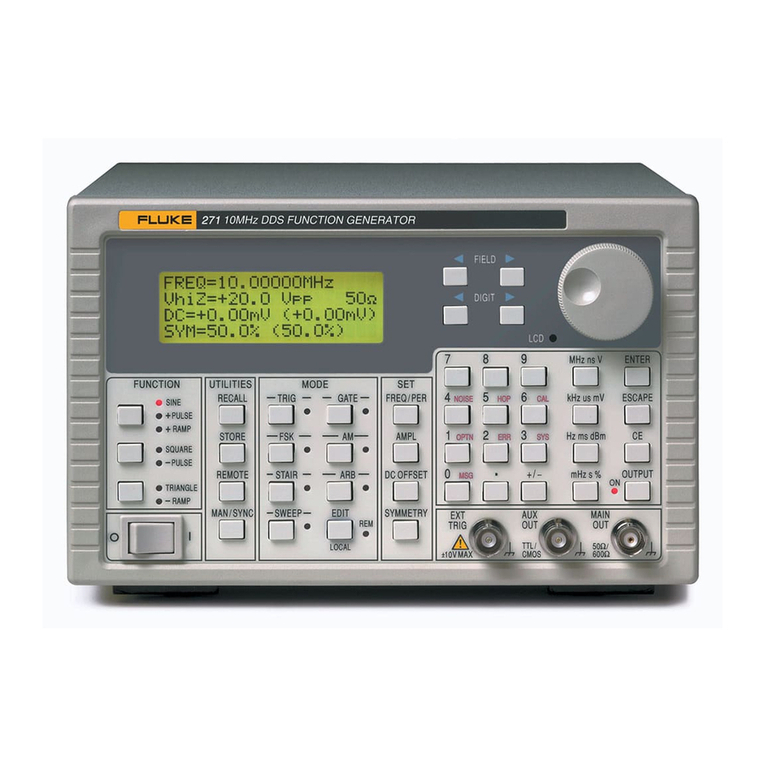
Figure 1. Single-Channel Arbitrary Waveform Generator Model 281
3

281, 282, 284
Getting Started Manual
Principal Controls and Connectors
The rotary control and the
two cursor keys below it
are used to change
parameter values in the
LCD display, such as
frequency, amplitude or dc
offset.
shy0018f.gif
Where the symbol appears next to a menu choice, the
rotary control lets you select the appropriate item from a
list.
Where a numeric parameter value is editable the flashing
cursor below one of the digits indicates the step by which
the rotary control will increment or decrement the value.
The flashing cursor can be moved left or right using the
keys below the rotary control.
The WAVE SELECT keys
call screens from which all
standard or already defined
arbitrary waveforms can be
selected.
shy0004f.giff
Pressing the STD key gives the STANDARD WAVEFORMS
screen on the LCD display, which lists the waveforms
available (sine, square, triangle, etc.)
Pressing the ARB key causes the LCD display to list the
arbitrary waveforms held in memory.
The SEQUENCE key is used when you want to create
sequences of arbitrary waveforms. (For information on the
programming and use of arbitrary waveforms, refer to the
Users Manual).
Pressing the SWEEP key brings up a menu of sweep
parameters: frequency range, sweep time, direction, etc.
4

Getting Started
Controls and Connections
WAVE EDIT keys call
screens from which
arbitrary waveforms can be
created, modified,
combined, etc.
The CREATE and MODIFY
keys allow you to create a
new waveform or modify an
existing waveform using the
front panel controls.
shy0005f.gif
FREQuency, AMPLitude,
OFFSET and MODE keys
display screens which
permit their respective
parameters to be edited
either from the numeric
keypad or by using the
rotary control and the
cursor keys.
shy0006f.gif
Frequency and amplitude are self-explanatory; OFFSET
refers to the instrument's ability to apply a dc offset voltage
to the waveform output, and the MODE key lets you
determine whether the output is continuous, triggered,
gated or swept and also provides for tone generation.
Numeric keys permit direct
entry of a value for the
parameter currently
selected. Values are
accepted in three formats:
integer (20), floating point
(20·0) and exponential (2
EXP 1).
shy0007f.gif
For example, to set a new frequency of 50 kHz, you can
press FREQ followed by 50000 ENTER or by 5 EXP 4
ENTER.
ENTER confirms the numeric entry and changes the
generator's setting to the new value.
CE (Clear Entry) undoes a numeric entry digit by digit.
ESCAPE returns a setting being edited to its previous
value.
5

281, 282, 284
Getting Started Manual
Each channel has a key
which directly switches the
MAIN OUT of that channel
on and off. The LED ON
lamp indicates when the
output is on.
The MAIN OUT socket is
the 50 output from the
channel’s main generator.
shy0008f.gif
It provides up to 20 V p-p into an open circuit or 10 V p-p
into a matched 50 load. It can tolerate a short circuit for
60 seconds.
The SYNC OUT key calls
an LCD display in which
you can set the parameters
of the sync output,
including whether the port
is on or off. The LED is lit
when the output is on.
shy0018f.gif
The SYNC OUT socket provides a TTL/CMOS level output
for a number of synchronization signals which you can
select using the front panel controls. It can be used to
trigger an oscilloscope or provide a Z-axis bright-up
marker, or to deliver various forms of gating and triggering
for external instruments and systems.
This drawing and the one above show the SYNC OUT and
MAIN OUT key, the LED and the socket for the single-
channel instrument. On the multi-channel instruments the
MAIN OUT sockets, LEDs and keys are grouped with their
corresponding SYNC OUT sockets, LEDs and keys.
6

Getting Started
Controls and Connections
The SUM socket accepts
an external signal in the
range ±10 V which can be
added to the signal
generated internally. Multi-
channel instruments can
also add signals internally
from one channel to the
next.
shy0010f.gif
Pressing the SUM key brings up an LCD screen in which
you can set the source, attenuation and on/off state. The
LED indicates whether the external signal is enabled or
not.
The MODULATION socket
accepts an external signal
in the range ±10 V which
you can use to modulate
the internally-generated
signal. Multi-channel
instruments can also use
signals generated in one
channel to modulate the
next channel.
shy0011f.gif
Pressing the MODULATION key brings up an LCD screen
in which you can set the source, modulation type and
on/off state. The LED indicates whether the external
modulation signal is enabled or not.
7

281, 282, 284
Getting Started Manual
The TRIG IN socket
accepts an external trigger
signal in the range ±10 V
(with a threshold at 1.5 V)
which you can use for burst
mode or for gating.
shy0012f.gif
Pressing the TRIG IN key brings up an LCD screen in
which you can set the source and slope of the trigger
signal.
The LED indicates whether the external trigger signal is
enabled or not.
The MAN TRIG key is
used for manual triggering
(when TRIG IN is
appropriately set) and for
synchronizing two or more
linked generators.
shy0013f.gif
The MAN HOLD key lets you manually pause arbitrary
waveform output and sweep; the output is held at the level
it was at when MAN HOLD was pressed.
The UTILITY key gives
access to menus for a
variety of functions such as
remote control interface
set-up, power-up
parameters, error message
settings, and storing and
recalling set-ups to and
from the instrument's
internal non-volatile
memory.
shy0014f.gif
8

Getting Started
Controls and Connections
The FILTER key brings up
an LCD display in which
you can override the
default output filter
settings.
shy0015f.gif
The STATUS key always
returns the display to the
default start-up screen
which gives an overview of
the generator's status.
Pressing STATUS again
returns the display to the
previous screen.
shy0020f.gif
The RECALL key is used to recall items from the
instrument's internal non-volatile memory. Multi-channel
instruments also have a STORE key; on the single-
channel instrument this function is provided via the
UTILITY menu.
The LOCAL key is used to bring the instrument back to
local (i.e. front panel) control when it has been used in
remote mode (indicated by the REMOTE LED).
Finally, the contrast of the LCD panel can be adjusted by
means of a rotary control behind the panel and accessed
using a small screwdriver through the hole marked LCD.
9

281, 282, 284
Getting Started Manual
The Liquid Crystal Display Panel
The 4-line x 20-character LCD panel is used to display
and edit all the parameter values and to indicate and
change modes.
Four soft keys at each side of the screen let you select
screen items. Selected items are indicated by a filled
diamond ( ) and unselected items by a hollow diamond
().
shy0017f.gif
Multi-Channel Instruments - Front Panel
Differences
The Users Manual contains drawings of the model 282
and 284 front panels.
The controls of the two- and four-channel versions are the
same as those of the single channel version in all respects
except:
1. there are two or four pairs (respectively) of MAIN OUT
and SYNC OUT sockets, and
2. the front panel is wider to accommodate the additional
outputs, which also means that the layout of the keys
is different, and
3. there are certain keys which do not exist on the
single-channel instrument, as follows:
10
Other manuals for 281
1
This manual suits for next models
2
Table of contents
Other Fluke Portable Generator manuals

Fluke
Fluke 291 Parts list manual

Fluke
Fluke PM5418 User manual

Fluke
Fluke PM5414V User manual

Fluke
Fluke 6080A User manual

Fluke
Fluke DDS Function Generator 271 Parts list manual

Fluke
Fluke 5128A User manual

Fluke
Fluke 291 User manual

Fluke
Fluke SimpliFiber 850 User manual

Fluke
Fluke Wavetek-Datron 395 Instruction Manual

Fluke
Fluke 6070A User manual